sensor TOYOTA MIRAI 2022 Owner's Guide
[x] Cancel search | Manufacturer: TOYOTA, Model Year: 2022, Model line: MIRAI, Model: TOYOTA MIRAI 2022Pages: 556, PDF Size: 17.34 MB
Page 249 of 556
2495-5. Using the driving support systems
Owners Manual_USA_M62084_en
5
Driving
*: If equipped
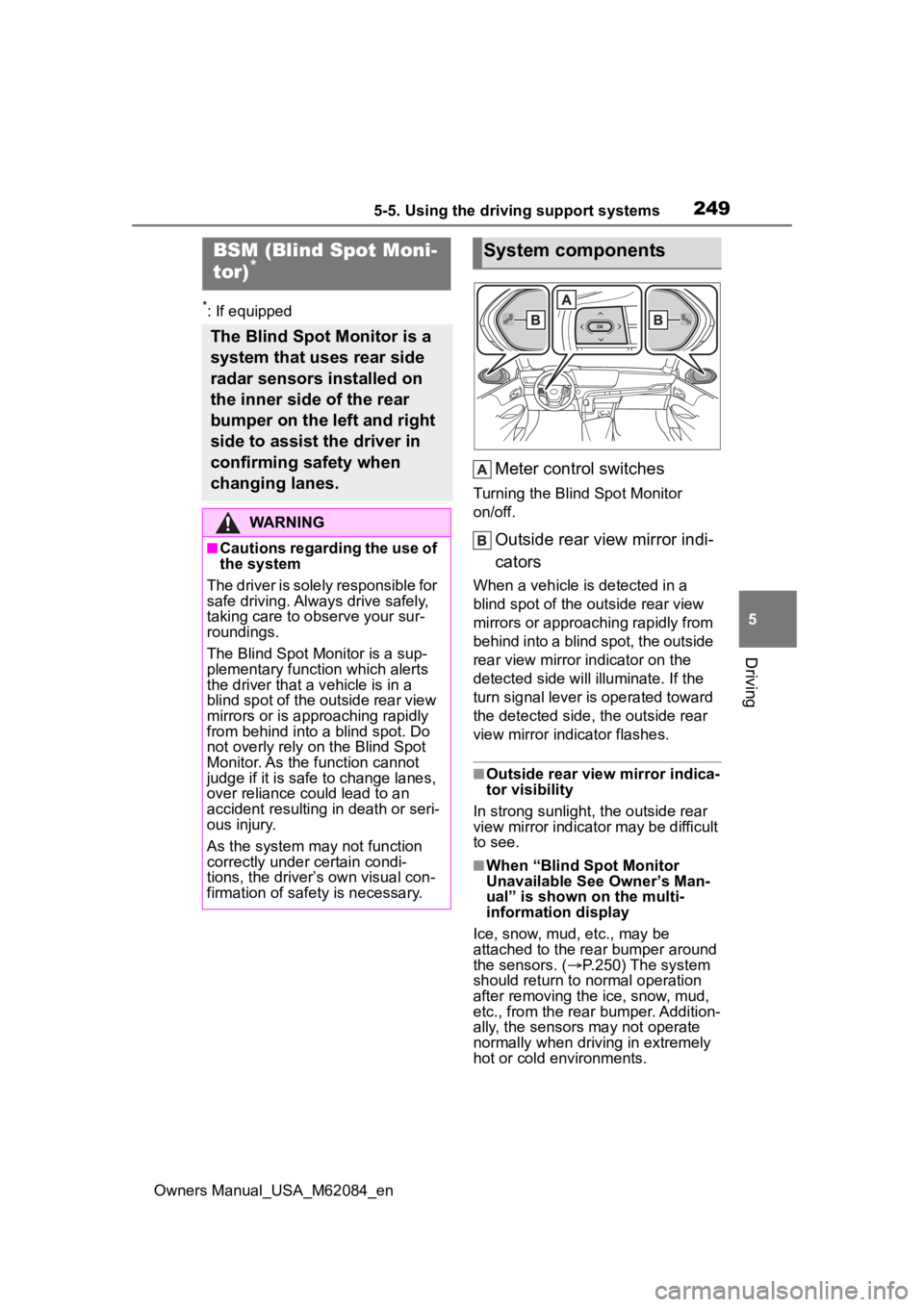
Meter control switches
Turning the Blind Spot Monitor
on/off.
Outside rear view mirror indi-
cators
When a vehicle is detected in a
blind spot of the outside rear view
mirrors or approaching rapidly from
behind into a blind spot, the outside
rear view mirror indicator on the
detected side will illuminate. If the
turn signal lever is operated toward
the detected side, the outside rear
view mirror indicator flashes.
■Outside rear vie w mirror indica-
tor visibility
In strong sunlight, the outside rear
view mirror indicator may be difficult
to see.
■When “Blind Spot Monitor
Unavailable See Owner’s Man-
ual” is shown on the multi-
information display
Ice, snow, mud, etc., may be
attached to the rear bumper around
the sensors. ( P.250) The system
should return to normal operation
after removing the ice, snow, mud,
etc., from the rear bumper. Addition-
ally, the sensors may not operate
normally when drivin g in extremely
hot or cold environments.
BSM (Blind Spot Moni-
tor)*
The Blind Spot Monitor is a
system that uses rear side
radar sensors installed on
the inner side of the rear
bumper on the left and right
side to assist the driver in
confirming safety when
changing lanes.
WARNING
■Cautions regarding the use of
the system
The driver is solely responsible for
safe driving. Always drive safely,
taking care to o bserve your sur-
roundings.
The Blind Spot Monitor is a sup-
plementary function which alerts
the driver that a v ehicle is in a
blind spot of the outside rear view
mirrors or is approaching rapidly
from behind into a blind spot. Do
not overly rely on the Blind Spot
Monitor. As the function cannot
judge if it is safe to change lanes,
over reliance could lead to an
accident resulting in death or seri-
ous injury.
As the system may not function
correctly under certain condi-
tions, the driver’s own visual con-
firmation of safety is necessary.
System components
Page 250 of 556
2505-5. Using the driving support systems
Owners Manual_USA_M62084_en
■When “Blind Spot Monitor Mal-
function Visit Your Dealer” is
shown on the multi-information
display
There may be a sensor malfunction
of misaligned. Have the vehicle
inspected by your Toyota dealer.
■Customization
Some functions can be customized.
( P.498)
■Certification
P. 5 4 8
WARNING
■To ensure the system can
operate properly
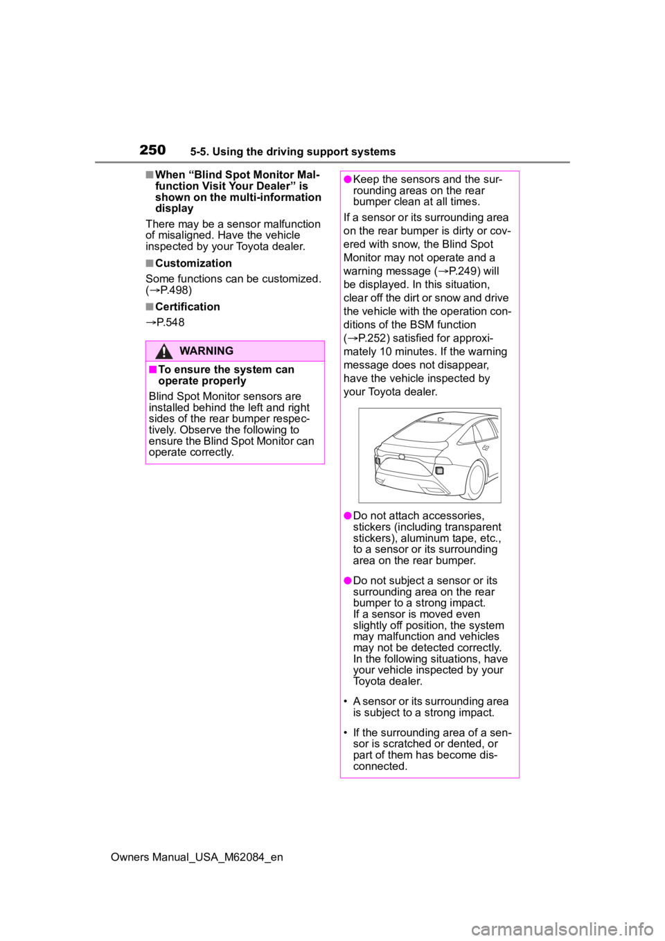
Blind Spot Monitor sensors are
installed behind the left and right
sides of the rear bumper respec-
tively. Observe the following to
ensure the Blind Spot Monitor can
operate correctly.
●Keep the sensors and the sur-
rounding areas on the rear
bumper clean at all times.
If a sensor or its surrounding area
on the rear bumper is dirty or cov-
ered with snow, the Blind Spot
Monitor may not operate and a
warning message ( P.249) will
be displayed. In this situation,
clear off the dirt or snow and drive
the vehicle with the operation con-
ditions of the BSM function
( P.252) satisfied for approxi-
mately 10 minutes. If the warning
message does not disappear,
have the vehicle inspected by
your Toyota dealer.
●Do not attach a ccessories,
stickers (including transparent
stickers), aluminum tape, etc.,
to a sensor or its surrounding
area on the rear bumper.
●Do not subject a sensor or its
surrounding area on the rear
bumper to a strong impact.
If a sensor is moved even
slightly off position, the system
may malfunction and vehicles
may not be detected correctly.
In the following si tuations, have
your vehicle inspected by your
Toyota dealer.
• A sensor or its surrounding area is subject to a strong impact.
• If the surrounding area of a sen- sor is scratched or dented, or
part of them h as become dis-
connected.
Page 251 of 556
2515-5. Using the driving support systems
Owners Manual_USA_M62084_en
5
Driving
Use the meter control switches
to turn on/off the function.
( P.100)
1 Press or to select .
2 Press or to select “
BSM” and then press .
When the BSM function is disabled,
the BSM OFF indicator illuminates.
(Each time the power switch is
turned off then ch anged to ON, the
Blind Spot Monitor will be enabled
automatically.)
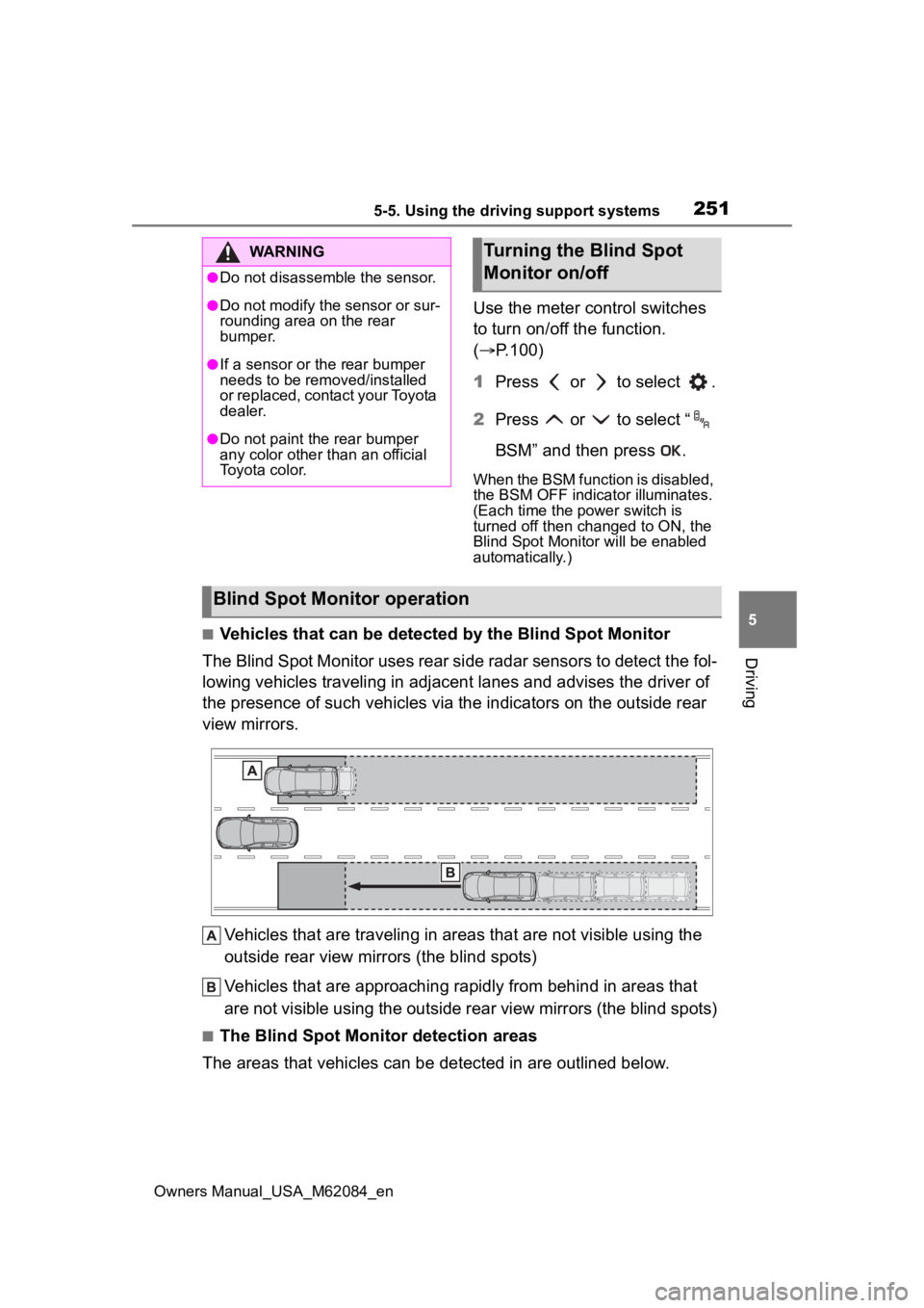
■Vehicles that can be detected by the Blind Spot Monitor
The Blind Spot Monitor uses rear side radar sensors to detect the fol-
lowing vehicles traveling in adjacent lanes and advises the driver of
the presence of such vehicles via the indicators on the outside rear
view mirrors.
Vehicles that are traveling in areas that are not visible using the
outside rear view mirrors (the blind spots)
Vehicles that are approaching r apidly from behind in areas that
are not visible using the outside rear view mirrors (the blind spots)
■The Blind Spot Monitor detection areas
The areas that vehicles can be detected in are outlined below.
WARNING
●Do not disassemble the sensor.
●Do not modify the sensor or sur-
rounding area on the rear
bumper.
●If a sensor or th e rear bumper
needs to be removed/installed
or replaced, contact your Toyota
dealer.
●Do not paint the rear bumper
any color other than an official
Toyota color.
Turning the Blind Spot
Monitor on/off
Blind Spot Monitor operation
Page 253 of 556

2535-5. Using the driving support systems
Owners Manual_USA_M62084_en
5
Driving
●Vehicles which are being over-
taken rapidly by your vehicle*
*
: Depending on the conditions, detection of a vehicle and/or
object may occur.
■Conditions under which the
system may not function cor-
rectly
●The Blind Spot Monitor may not
detect vehicles correctly in the fol-
lowing situations:
• When the sensor is misaligned
due to a strong impact to the sen-
sor or its surrounding area
• When mud, snow, ice, a sticker,
etc., is covering the sensor or sur-
rounding area on the rear bumper
• When driving on a road surface
that is wet with standing water
during bad weather, such as
heavy rain, snow, or fog
• When multiple vehicles are approaching with only a small gap
between each vehicle
• When the distanc e between your
vehicle and a following vehicle is
short
• When there is a significant differ-
ence in speed between your vehi-
cle and the vehicle that enters the
detection area
• When the difference in speed between your vehicle and another
vehicle is changing
• When a vehicle enters a detection area traveling at about the same
speed as your vehicle
• As your vehicle starts from a stop, a vehicle remains in the detection
area
• When driving up and down con- secutive steep inclines, such as
hills, dips in the road, etc.
• When driving on roads with sharp bends, consecutive curves, or
uneven surfaces
• When vehicle lanes are wide, or when driving on the edge of a
lane, and the vehicle in an adja-
cent lane is far away from your
vehicle
• When an accessory (such as a bicycle carrier) is installed to the
rear of the vehicle
• When there is a significant differ-
ence in height between your vehi-
cle and the vehicle that enters the
detection area
• Immediately after the Blind Spot Monitor is turned on
●Instances of the Blind Spot Moni-
tor unnecessarily d etecting a vehi-
cle and/or object m ay increase in
the following situations:
• When the sensor is misaligned due to a strong impact to the sen-
sor or its surrounding area
• When the distance between your vehicle and a guardrail, wall, etc.,
that enters the detection area is
short
• When driving up and down con-
secutive steep inclines, such as
hills, dips in the road, etc.
• When vehicle lanes are narrow, or
when driving on the edge of a
lane, and a vehicle traveling in a
lane other than the adjacent lanes
enters the detection area
• When driving on r oads with sharp
bends, consecutive curves, or
uneven surfaces
• When the tires are slipping or spinning
• When the distance between your vehicle and a following vehicle is
short
• When an accessory (such as a bicycle carrier) is installed to the
rear of the vehicle
Page 254 of 556
2545-5. Using the driving support systems
Owners Manual_USA_M62084_en
*: If equipped
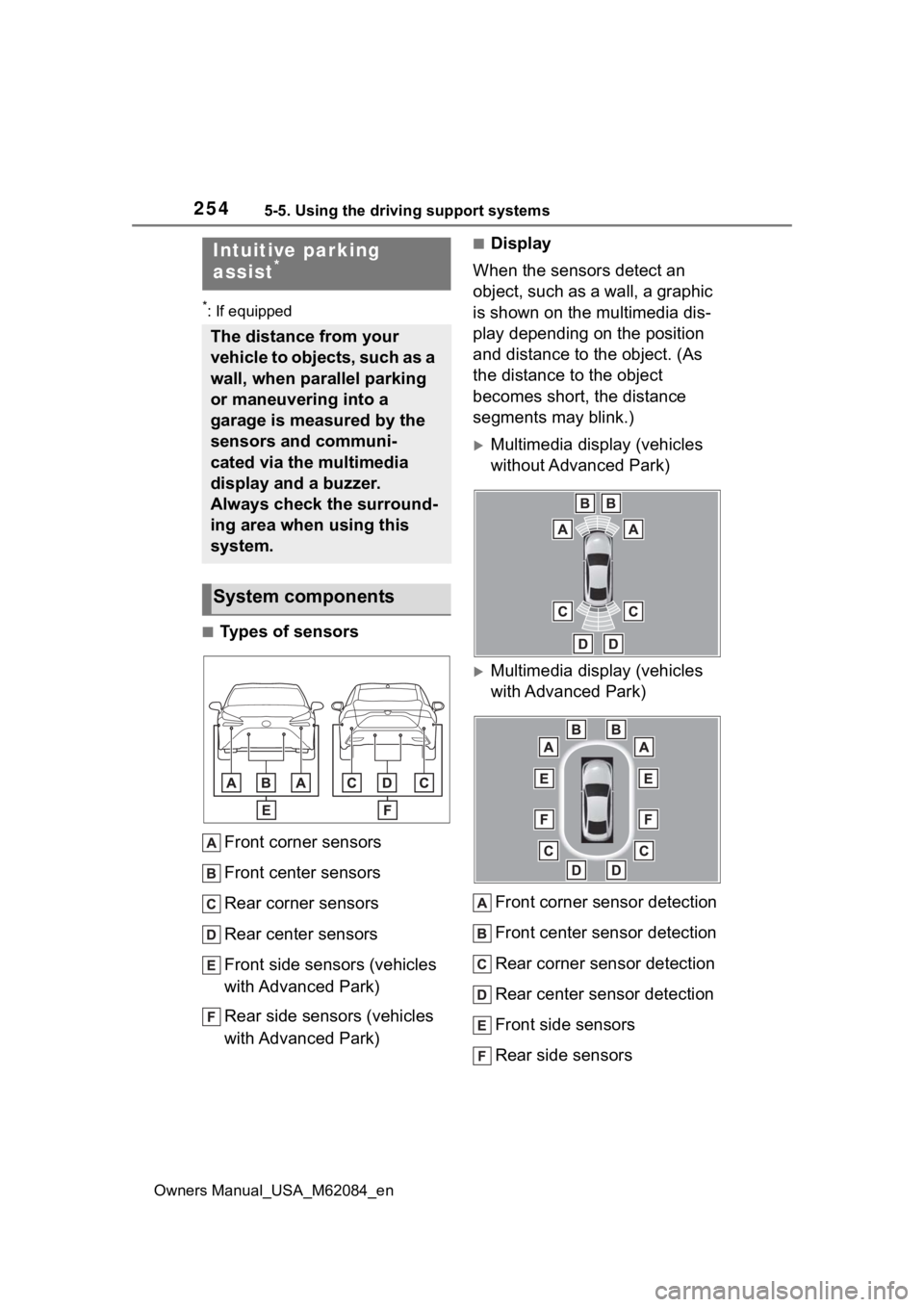
■Types of sensorsFront corner sensors
Front center sensors
Rear corner sensors
Rear center sensors
Front side sensors (vehicles
with Advanced Park)
Rear side sensors (vehicles
with Advanced Park)
■Display
When the sensors detect an
object, such as a wall, a graphic
is shown on the multimedia dis-
play depending on the position
and distance to the object. (As
the distance to the object
becomes short, the distance
segments may blink.)
Multimedia display (vehicles
without Advanced Park)
Multimedia display (vehicles
with Advanced Park)
Front corner sensor detection
Front center sensor detection
Rear corner sensor detection
Rear center sensor detection
Front side sensors
Rear side sensors
Intuitive parking
assist*
The distance from your
vehicle to objects, such as a
wall, when parallel parking
or maneuvering into a
garage is measured by the
sensors and communi-
cated via the multimedia
display and a buzzer.
Always check the surround-
ing area when using this
system.
System components
Page 255 of 556
2555-5. Using the driving support systems
Owners Manual_USA_M62084_en
5
Driving
Use the meter control switches
to enable/disable the intuitive
parking assist. ( P.100)
1 Press or to select .
2 Press or to select
and then press .
When the intuitive parking assist
function is disabled, the intuitive
parking assist OFF indicator
( P.94) illuminates.
To re-enable the system when it
was disabled, select on the
multi-information display, select and then On. If disabled using
this method, the system will not be
re-enabled by turning the power
switch off and then to ON.
Turning intuitive parking
assist on/off
WARNING
■Cautions regarding the use of
the system
There is a limit to the degree of
recognition accuracy and control
performance that this system can
provide, do not ov erly rely on this
system. The driver is always
responsible for paying attention to
the vehicle’ surroundings and
driving safely.
■To ensure the system can
operate properly
Observe the following precau-
tions.
Failing to do so may result in the
vehicle being unable to be driven
safely and possibly cause an acci-
dent.
●Do not damage the sensors,
and always keep them clean.
●Do not attach a sticker or install
an electronic component, such
as a backlit licen se plate (espe-
cially fluorescent type), fog
lights, fender po le or wireless
antenna near a radar sensor.
●Do not subject the surrounding
area of the sensor to a strong
impact. If subjected to an
impact, have the vehicle
inspected by your Toyota
dealer. If the front or rear
bumper needs to be
emoved/installed or replaced,
contact your Toyota dealer.
●Do not modify, disassemble or
paint the sensors.
●Do not attach a license plate
cover.
●Keep your tires properly
inflated.
■When to disable the function
In the following situations, disable
the function as it may operate
even though there is no possibility
of a collision.
●Failing to observe the warnings
above.
●A non-genuine Toyota suspen-
sion (lowered suspension, etc.)
is installed.
■Notes when washing the vehi-
cle
Do not apply intensive bursts of
water or steam to the sensor
area.
Doing so may result in the sensor
malfunctioning.
Page 256 of 556
2565-5. Using the driving support systems
Owners Manual_USA_M62084_en
■The system can be operated
when
●The power switch is in ON.
●Intuitive parking assist function is
on.
●The vehicle speed is less than
about 6 mph (10 km/h).
●A shift position other than P is
selected.
■If “Clean Parking Assist Sen-
sor” is displayed on the multi-
information display
A sensor may be covered with water
drops, ice, snow, d irt, etc. Remove
the water drops, ice, snow, dirt, etc.,
from the sensor to return the system
to normal.
Also, due to ice forming on a sensor
at low temperatures, a warning
message may be displayed or the
sensor may not be able to detect an
object. Once the ice melts, the sys-
tem will return to normal.
If a warning message is displayed
even if the sensor is clean, there
may be a sensor malfunction. Have
the vehicle inspected by your Toyota
dealer.
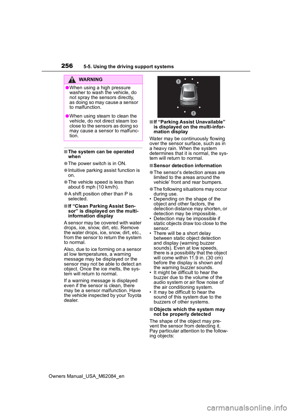
■If “Parking Assist Unavailable”
is displayed on the multi-infor-
mation display
Water may be continuously flowing
over the sensor surface, such as in
a heavy rain. When the system
determines that it is normal, the sys-
tem will return to normal.
■Sensor detection information
●The sensor’s detection areas are
limited to the areas around the
vehicle’ front and rear bumpers.
●The following situations may occur
during use.
• Depending on the shape of the object and other factors, the
detection distance may shorten, or
detection may be impossible.
• Detection may be impossible if
static objects draw too close to the
sensor.
• There will be a short delay
between static object detection
and display (warning buzzer
sounds). Even at low speeds,
there is a possibility that the object
will come within 11.9 in. (30 cm)
before the display is shown and
the warning buzzer sounds.
• It might be diffic ult to hear the
buzzer due to the volume of the
audio system or air flow noise of
the air conditioning system.
• It may be diffi cult to hear the
sound of this sys tem due to the
buzzers of other systems.
■Objects which the system may
not be properly detected
The shape of the object may pre-
vent the sensor from detecting it.
Pay particular attent ion to the follow-
ing objects:
WARNING
●When using a high pressure
washer to wash the vehicle, do
not spray the sensors directly,
as doing so may cause a sensor
to malfunction.
●When using steam to clean the
vehicle, do not direct steam too
close to the sensors as doing so
may cause a sens or to malfunc-
tion.
Page 257 of 556
2575-5. Using the driving support systems
Owners Manual_USA_M62084_en
5
Driving
●Wires, fences, ropes, etc.
●Cotton, snow and other materials
that absorb sound waves
●Sharply-angled objects
●Low objects
●Tall objects with upper sections
projecting outwards in the direc-
tion of your vehicle
■Situations in which the system
may not operate properly
Certain vehicle conditions and the
surrounding environment may affect
the ability of a sensor to correctly
detect objects. Particular instances
where this may occur are listed
below.
●There is dirt, snow, water drops or
ice on a sensor. (Cleaning the
sensors will resolve this problem.)
●A sensor is frozen. (Thawing the
area will resolve this problem.)
In especially cold weather, if a
sensor is frozen the sensor dis-
play may be displayed abnormally,
or objects, such as a wall, may not
be detected.
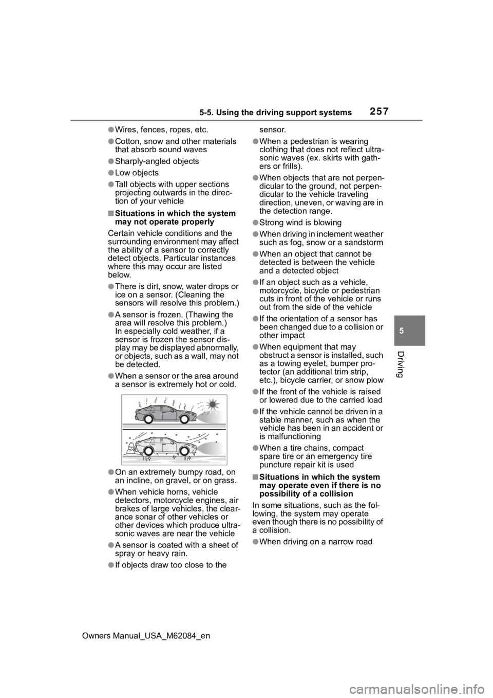
●When a sensor or the area around
a sensor is extremely hot or cold.
●On an extremely bumpy road, on
an incline, on gravel, or on grass.
●When vehicle horns, vehicle
detectors, motorcycle engines, air
brakes of large vehicles, the clear-
ance sonar of other vehicles or
other devices which produce ultra-
sonic waves are near the vehicle
●A sensor is coated with a sheet of
spray or heavy rain.
●If objects draw too close to the sensor.
●When a pedestrian is wearing
clothing that does not reflect ultra-
sonic waves (ex. skirts with gath-
ers or frills).
●When objects that are not perpen-
dicular to the ground, not perpen-
dicular to the vehicle traveling
direction, uneven, or waving are in
the detection range.
●Strong wind is blowing
●When driving in inclement weather
such as fog, snow or a sandstorm
●When an object that cannot be
detected is between the vehicle
and a detected object
●If an object such as a vehicle,
motorcycle, bicycle or pedestrian
cuts in front of the
vehicle or runs
out from the side of the vehicle
●If the orientation of a sensor has
been changed due to a collision or
other impact
●When equipment that may
obstruct a sensor is installed, such
as a towing eyelet, bumper pro-
tector (an additional trim strip,
etc.), bicycle car rier, or snow plow
●If the front of the v ehicle is raised
or lowered due to the carried load
●If the vehicle cannot be driven in a
stable manner, such as when the
vehicle has been in an accident or
is malfunctioning
●When a tire chains, compact
spare tire or an emergency tire
puncture repair kit is used
■Situations in which the system
may operate even if there is no
possibility of a collision
In some situations, such as the fol-
lowing, the system may operate
even though there is no possibility of
a collision.
●When driving on a narrow road
Page 258 of 556
2585-5. Using the driving support systems
Owners Manual_USA_M62084_en
●When driving toward a banner,
flag, low-hanging branch or boom
barrier (such as those used at rail-
road crossings, toll gates and
parking lots)
●When there is a rut or hole in the
surface of the road
●When driving on a metal cover
(grating), such as those used for
drainage ditches
●When driving up or down a steep
slope
●If a sensor is hit by a large amount
of water, such as when driving on
a flooded road
●There is dirt, snow, water drops or
ice on a sensor. (Cleaning the
sensors will resolve this problem.)
●A sensor is coated with a sheet of
spray or heavy rain
●When driving in inclement weather
such as fog, snow or a sandstorm
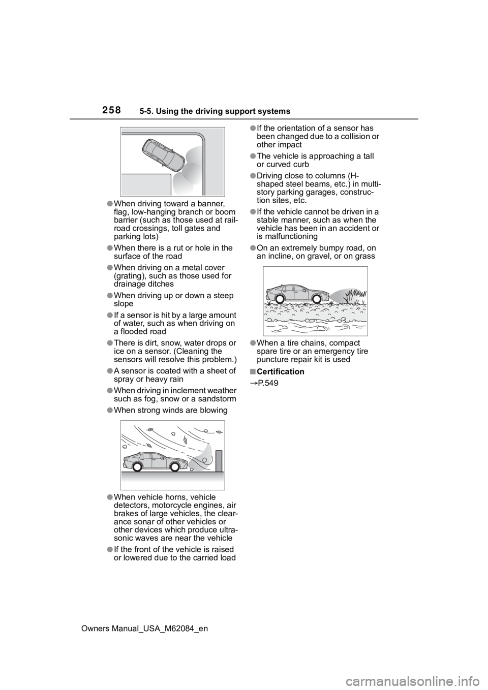
●When strong winds are blowing
●When vehicle horns, vehicle
detectors, motorcycle engines, air
brakes of large vehicles, the clear-
ance sonar of other vehicles or
other devices which produce ultra-
sonic waves are near the vehicle
●If the front of the vehicle is raised
or lowered due to the carried load
●If the orientation of a sensor has
been changed due to a collision or
other impact
●The vehicle is approaching a tall
or curved curb
●Driving close to columns (H-
shaped steel beams, etc.) in multi-
story parking garages, construc-
tion sites, etc.
●If the vehicle cannot be driven in a
stable manner, such as when the
vehicle has been in an accident or
is malfunctioning
●On an extremely bumpy road, on
an incline, on gravel, or on grass
●When a tire chains, compact
spare tire or an emergency tire
puncture repair kit is used
■Certification
P.549
Page 259 of 556
2595-5. Using the driving support systems
Owners Manual_USA_M62084_en
5
Driving
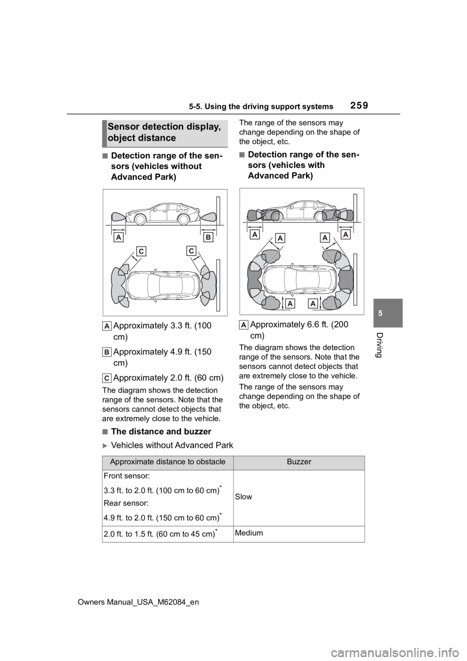
■Detection range of the sen-
sors (vehicles without
Advanced Park) Approximately 3.3 ft. (100
cm)
Approximately 4.9 ft. (150
cm)
Approximately 2.0 ft. (60 cm)
The diagram shows the detection
range of the sensors. Note that the
sensors cannot detect objects that
are extremely close to the vehicle. The range of the sensors may
change depending on the shape of
the object, etc.
■Detection range of the sen-
sors (vehicles with
Advanced Park)
Approximately 6.6 ft. (200
cm)
The diagram shows the detection
range of the sensors. Note that the
sensors cannot detect objects that
are extremely clos e to the vehicle.
The range of the sensors may
change depending on the shape of
the object, etc.
■The distance and buzzer
Vehicles without Advanced Park
Sensor detection display,
object distance
Approximate distance to obstacleBuzzer
Front sensor:
3.3 ft. to 2.0 ft. (100 cm to 60 cm)
*
Rear sensor:
4.9 ft. to 2.0 ft. (150 cm to 60 cm)
*
Slow
2.0 ft. to 1.5 ft. (60 cm to 45 cm)*Medium