ignition TOYOTA PROACE CITY VERSO 2020 Repair Manual
[x] Cancel search | Manufacturer: TOYOTA, Model Year: 2020, Model line: PROACE CITY VERSO, Model: TOYOTA PROACE CITY VERSO 2020Pages: 272, PDF Size: 58.6 MB
Page 144 of 272
144
NOTIC E
The images from the camera(s) displayed on the touch screen may be distorted by the terrain.In shady areas, or in inadequate sunlight or lighting conditions, the image may be darkened and with lower contrast
The manoeuvre can be permanently interrupted at any time, either by the driver or automatically by the system.Interruption by the driver:– taking over control of the steering.– activating the direction indicator lamps on the opposite side to that of the manoeuvre.– unfastening the driver's seat belt.– switching off the ignition.Interruption by the system:– vehicle exceeding the speed limit of 7 km/h (5 mph) during parking space entry manoeuvres, or 5 km/h (3 mph) during parking space exit manoeuvres.
– activation of anti-slip regulation on a slippery road.– opening of a door or the boot.– engine stall.– system malfunction.– after 10 manoeuvres to enter or exit a parallel parking space and after 7 manoeuvres to enter a parking bay.Interrupting the manoeuvre automatically
deactivates the function.
The manoeuvre symbol is displayed in red, accompanied by the "Manoeuvre cancelled" message on the touch screen.A message prompts the driver to take back control of the vehicle.The function is deactivated after a few seconds; this warning lamp goes off and the function returns to the initial display.
End of the parking space entry or exit
manoeuvre
The vehicle stops as soon as the manoeuvre is completed.The manoeuvre symbol is displayed in red, accompanied by the message “Manoeuvre completed” on the touch screen.When the function is deactivated, this indicator lamp goes off, accompanied by an audible signal.When entering a parking space, the driver may be required to complete the manoeuvre.
Operating limits
– The system may suggest an unsuitable parking space (No Parking area, work in progress with damaged road surface, location alongside a ditch, etc.).– The system may indicate that a space has been found but not offer it because of a fixed obstacle on the opposite side of the manoeuvre, which would not allow the vehicle to follow the necessary trajectory for parking.
– The system may indicate that a space has been found but not engage the manoeuvre because the road is too narrow.– The system is not designed to perform the parking manoeuvre on a sharp bend.– The system does not detect spaces that are much larger than the vehicle or are bounded by obstacles that are very low (pavements, studs, etc.) or very thin (trees, posts, wire fences, etc.).– Certain obstacles located in the sensors’ blind spots may not be detected or may no longer be detected during the manoeuvre.– Certain materials (fabrics) absorb sound waves: pedestrians may not be detected.– A front or rear impact to the vehicle can upset the sensors’ settings, which is not always detected by the system: distance measurements may be distorted.– If the boot is heavily loaded, the vehicle may tilt, affecting distance measurements.The vehicle's sensors and camera(s) may be impaired by:– accumulated snow or fallen leaves on the
road,– adverse weather conditions (heavy rain, thick fog, falling snow),– noise interference from noisy vehicles and machinery (lorries, pneumatic drills, etc.).
Page 146 of 272

146
Compatibility of fuels
Petrol fuels conforming to the EN228 standard containing up to 5% and 10% ethanol respectively.
Diesel fuels conforming to the EN590, EN16734 and EN16709 standards and containing up to 7%, 10%, 20% and 30% fatty acid methyl ester respectively. The use of B20 or B30 fuels, even occasionally, imposes special maintenance conditions referred to as "Arduous conditions".
Paraffinic Diesel fuel conforming to the EN15940 standard.
WARNI NG
The use of any other type of (bio) fuel (vegetable or animal oils, pure or diluted, domestic fuel, etc.) is strictly prohibited (risk of damage to the engine and fuel system).
NOTIC E
The only fuel additives authorised for use are those that meet the B715001 (petrol) or B715000 (Diesel) standards.
Diesel at low temperature
At temperatures below 0 °C (+32 °F), the formation of paraffins in summer-type Diesel fuels could prevent the engine from operating correctly. In these temperature conditions, use winter-type Diesel fuel and keep the fuel tank more than 50 % full.At temperatures below -15 °C (+5 °F) to avoid problems starting, it is best to park the vehicle under shelter (heated garage).
Travelling abroad
Certain fuels could damage your vehicle’s engine.In certain countries, the use of a particular fuel may be required (specific octane rating, specific trade name, etc.) to ensure correct operation of the engine.For all additional information, consult a dealer.
Refuelling
Fuel tank capacity: approximately 61 litres (petrol) or 50 litres (Diesel).Reserve level: approximately 6 litres.
Low fuel level
/2
1 1When the low fuel level is reached, this warning lamp comes on on the instrument panel, accompanied by an onscreen message and an audible signal. When it first
comes on, about 6 litres of fuel remain in the tank.Until sufficient fuel is added, this warning lamp appears every time the ignition is switched on, accompanied by an onscreen message and an audible signal. When driving, this message and audible signal are repeated with increasing frequency as the fuel level drops towards 0.You must refuel as soon as possible to avoid running out of fuel.For more information on Running out of fuel (Diesel), refer to the corresponding section.
W
ARNI NG
Stop & StartNever refuel with the engine in STOP mode; you must switch off the ignition.
Refuelling
At least 10 litres of fuel must be added, in order to be registered by the fuel gauge.
Opening the filler cap may create a noise caused by an inrush of air. This is entirely normal and results from the sealing of the fuel system.To refuel in complete safety:► Always switch off the engine.► Unlock the vehicle using the Keyless Entry and Starting.► Open the fuel filler flap.
Page 153 of 272
153
Practical information
7
WARNI NG
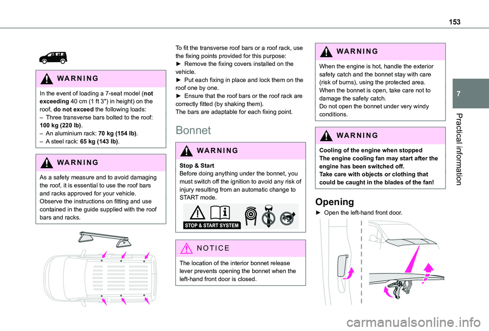
In the event of loading a 7-seat model (not exceeding 40 cm (1 ft 3") in height) on the roof, do not exceed the following loads:– Three transverse bars bolted to the roof: 100 kg (220 lb).– An aluminium rack: 70 kg (154 lb).– A steel rack: 65 kg (143 lb).
W ARNI NG
As a safety measure and to avoid damaging the roof, it is essential to use the roof bars and racks approved for your vehicle.Observe the instructions on fitting and use contained in the guide supplied with the roof bars and racks.
To fit the transverse roof bars or a roof rack, use the fixing points provided for this purpose:► Remove the fixing covers installed on the vehicle.► Put each fixing in place and lock them on the roof one by one.► Ensure that the roof bars or the roof rack are correctly fitted (by shaking them).The bars are adaptable for each fixing point.
Bonnet
WARNI NG
Stop & StartBefore doing anything under the bonnet, you must switch off the ignition to avoid any risk of injury resulting from an automatic change to START mode.
NOTIC E
The location of the interior bonnet release lever prevents opening the bonnet when the left-hand front door is closed.
WARNI NG
When the engine is hot, handle the exterior safety catch and the bonnet stay with care (risk of burns), using the protected area.When the bonnet is open, take care not to damage the safety catch.Do not open the bonnet under very windy conditions.
WARNI NG
Cooling of the engine when stoppedThe engine cooling fan may start after the engine has been switched off.Take care with objects or clothing that could be caught in the blades of the fan!
Opening
► Open the left-hand front door.
Page 155 of 272

155
Practical information
7
WARNI NG
Take care when working under the bonnet, as certain areas of the engine may be extremely hot (risk of burns) and the cooling fan could start at any time (even with the ignition off).
Used products
WARNI NG
Avoid prolonged contact of used oil or fluids with the skin.Most of these fluids are harmful to health and very corrosive.
ECO
Do not discard used oil or fluids into sewers or onto the ground.Empty used oil into the containers reserved for this purpose at a TOYOTA dealer or a qualified workshop.
Engine oil
The level is checked, with the engine having been switched off for at least 30
minutes and on level ground, either using the oil level indicator in the instrument panel when the ignition is switched on (for vehicles equipped with an electric gauge), or using the dipstick.
It is normal to top up the oil level between two services (or oil changes). It is recommended that you check the level, and top up if necessary, every 5,000 km (3,000 miles).
WARNI NG
In order to maintain the reliability of the engine and emissions control system, never use additives in the engine oil.
Checking using the dipstick
For the location of the dipstick, please refer to the illustration of the corresponding engine compartment.► Grasp the dipstick by its coloured grip and pull it out completely.► Wipe the end of the dipstick using a clean, lint-free cloth.
► Reinsert the dipstick and push fully down, then pull it out again to visually check the oil level: the correct level is between marks A (max) and B (min).Do not start the engine if the level is:– above mark A: contact a TOYOTA dealer or a qualified workshop.
– below mark B: top up the engine oil immediately.
WARNI NG
Oil gradeBefore topping up or changing the engine oil, check that the oil is suitable for the engine and complies with the recommendations in the service schedule supplied with the vehicle
(or available from your TOYOTA dealer and qualified workshops).Use of non-recommended oil may invalidate the contractual warranty in the event of engine failure.
Topping up the engine oil level
The location of the oil filler cap is shown in the corresponding underbonnet layout view.► Add oil in small quantities, avoiding any spills on engine components (risk of fire).► Wait a few minutes before checking the level again using the dipstick.► Add more oil if necessary.► After checking the level, carefully refit the oil filler cap and the dipstick in its tube.
NOTIC E
During the 30 minutes after topping up the oil, the check performed with the oil level indicator in the instrument panel when the ignition is switched on is not valid.
Page 160 of 272
160
Precautions for use
AdBlue® is a urea-based solution. This fluid is non-flammable, colourless and odourless (when kept in a cool place).In the event of contact with the skin, wash the affected area with soap and running water. In the event of contact with the eyes, immediately rinse the eyes with large amounts of water or with an eye wash solution for at least 15 minutes. Seek medical attention if you feel a persistent burning sensation or irritation.If swallowed, immediately wash out the mouth with clean water and then drink plenty of water.In certain conditions (high temperature, for example), the risk of release of ammonia cannot be excluded: do not inhale the fluid. Ammonia vapours have an irritant effect on mucous membranes (eyes, nose and throat).
WARNI NG
Store AdBlue® out of the reach of children, in its original container.
Procedure
Before starting the top-up procedure, ensure that the vehicle is parked on a flat and level surface.In wintry conditions, ensure that the temperature of the vehicle is above -11 °C. Otherwise the AdBlue® may be frozen and so cannot be poured into its tank. Park the vehicle in a warmer area
for a few hours to allow the top-up to be carried out.
WARNI NG
Never put the AdBlue® into the Diesel fuel tank.
WARNI NG
If any AdBlue® is splashed, or if there are any spillages on the bodywork, rinse immediately with cold water or wipe with a damp cloth.If the fluid has crystallised, clean it off using a sponge and hot water.
WARNI NG
Important: in the event of a top-up after a breakdown because of a lack of AdBlue, it is essential to wait around 5 minutes before switching on the ignition, without opening the driver’s door, unlocking the vehicle, introducing the key into the ignition switch, or introducing the key of the “Keyless Entry and Starting ” system into the passenger compartment.Switch on the ignition, then wait for 10 seconds before starting the engine.
► Switch off the ignition and remove the key from the switch to switch off the engine.
or► With Keyless Entry and Starting, press the "START/STOP" button to switch off the engine.
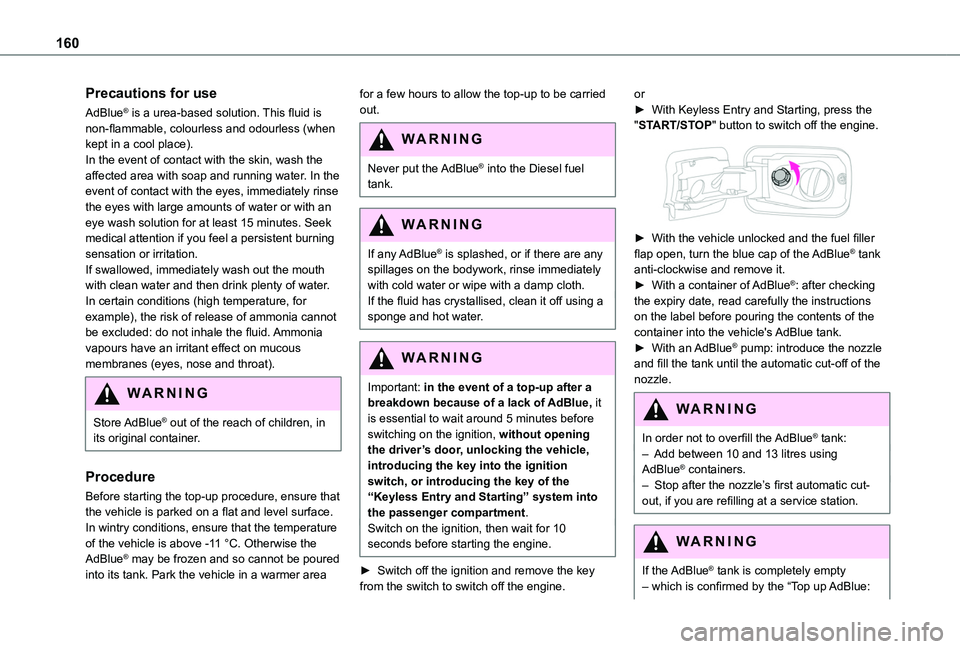
► With the vehicle unlocked and the fuel filler flap open, turn the blue cap of the AdBlue® tank anti-clockwise and remove it.► With a container of AdBlue®: after checking the expiry date, read carefully the instructions on the label before pouring the contents of the container into the vehicle's AdBlue tank.► With an AdBlue® pump: introduce the nozzle and fill the tank until the automatic cut-off of the nozzle.
WARNI NG
In order not to overfill the AdBlue® tank:– Add between 10 and 13 litres using AdBlue® containers.– Stop after the nozzle’s first automatic cut-out, if you are refilling at a service station.
WARNI NG
If the AdBlue® tank is completely empty – which is confirmed by the “Top up AdBlue:
Page 161 of 272
161
Practical information
7
Starting impossible” message – it is essential to add at least 5 litres.
After refilling
► Refit the blue cap to the tank filler and turn it clockwise, as far as it will go.► Close the fuel filler flap.
Do not dispose of AdBlue® bottles or containers in the household waste.Place them in a container reserved for this purpose or take them back to where you purchased them.
Free-wheeling
In certain situations, you must allow the vehicle to free-wheel (while being towed, on a rolling road, in an automatic car wash, or being transported by rail or sea freight, etc.).
The procedure varies according to the type of gearbox and parking brake.
With a manual gearbox and
electric parking brake /
Release procedure
► With the engine running and while depressing the brake pedal, move the gear selector to the neutral position.► While depressing the brake pedal, switch off the ignition.► Release the brake pedal, then switch on the ignition again.► While depressing the brake pedal, press the control lever to release the parking brake.► Release the brake pedal, then switch off the ignition.
Reverting to normal operation
► While depressing the brake pedal, start the engine.
With an automatic gearbox
and electric parking brake /
Release procedure
► With the engine running and while depressing the brake pedal, set the gear selector to N.► While depressing the brake pedal, switch off the ignition.► Release the brake pedal, then switch on the ignition again.► While depressing the brake pedal, press the control lever to release the parking brake.► Release the brake pedal, then switch off the
ignition.
Reverting to normal operation
► While depressing the brake pedal, start the engine.
NOTIC E
Keyless Entry and StartingYou must not depress the brake pedal while switching the ignition on or off. If you do, the engine will start, requiring you to restart the procedure.
Advice on care and
maintenance
General recommendations
Observe the following recommendations to avoid damaging your vehicle.
Exterior
WARNI NG
Never use a high-pressure jet wash in the engine compartment, due to the risk of damaging electrical components.Do not wash the vehicle in strong sunshine or extremely cold conditions.
Page 163 of 272
163
In the event of a breakdown
8
Running out of fuel
(Diesel)
On vehicles fitted with Diesel engines, the fuel system must be primed if you run out of fuel.If the engine does not start first time, do not keep trying, but start the procedure again from the beginning.
NOTIC E
For more information on Misfuel prevention (Diesel), refer to the corresponding section.
With Euro 6.2/6.3 engines
► Switch on the ignition (without starting the engine).► Wait around 1 minute and switch off the ignition.► Operate the starter motor to start the engine.If the engine does not start at the first attempt, do not keep trying, but restart the procedure.
Tool kit
► For easier access, move the seat(s) forward.
Accessing the tools
With a temporary puncture repair kit
The kit is located under the right-hand front seat.
With spare wheel
The jack is located under the right-hand front seat.The tools are located under the left-hand front seat.
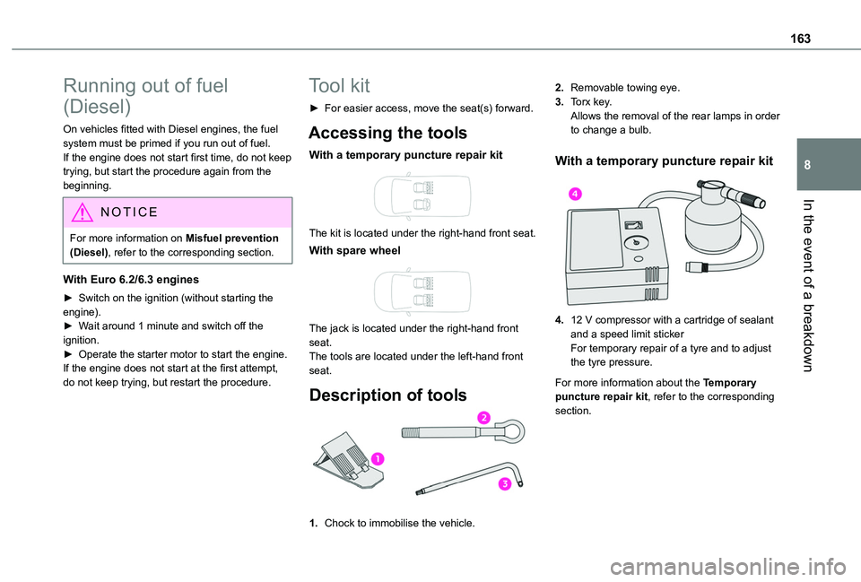
Description of tools
1.Chock to immobilise the vehicle.
2.Removable towing eye.
3.Torx key.Allows the removal of the rear lamps in order to change a bulb.
With a temporary puncture repair kit
4.12 V compressor with a cartridge of sealant and a speed limit stickerFor temporary repair of a tyre and to adjust the tyre pressure.
For more information about the Temporary puncture repair kit, refer to the corresponding section.
Page 164 of 272
164
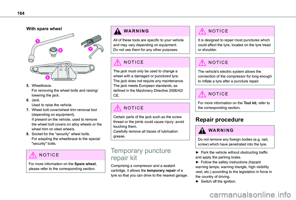
With spare wheel
5.Wheelbrace.For removing the wheel bolts and raising/lowering the jack.
6.Jack.Used to raise the vehicle.
7.Wheel bolt cover/wheel trim removal tool (depending on equipment).If present on the vehicle, used to remove the wheel bolt covers on alloy wheels or the wheel trim on steel wheels.
8.Socket for the “security” wheel bolts.For adapting the wheelbrace to the special "security" bolts.
NOTIC E
For more information on the Spare wheel, please refer to the corresponding section.
WARNI NG
All of these tools are specific to your vehicle and may vary depending on equipment.Do not use them for any other purposes.
NOTIC E
The jack must only be used to change a
wheel with a damaged or punctured tyre.The jack does not require any maintenance.The jack meets European standards, as defined in the Machinery Directive 2006/42/CE.
NOTIC E
Certain parts of the jack such as the screw thread or the joints could cause injury: avoid touching them.Carefully remove all traces of lubrication grease.
Temporary puncture
repair kit
Comprising a compressor and a sealant
cartridge, it allows the temporary repair of a tyre so that you can drive to the nearest garage.
NOTIC E
It is designed to repair most punctures which could affect the tyre, located on the tyre tread or shoulder.
NOTIC E
The vehicle's electric system allows the connection of the compressor for long enough to inflate a tyre after a puncture repair.
NOTIC E
For more information on the Tool kit, refer to the corresponding section.
Repair procedure
WARNI NG
Do not remove any foreign bodies (e.g. nail, screw) which have penetrated into the tyre.
► Park the vehicle without obstructing traffic and apply the parking brake.► Follow the safety instructions (hazard warning lamps, warning triangle, high visibility vest, etc.) according to the legislation in force in the country of driving.► Switch off the ignition.
Page 165 of 272

165
In the event of a breakdown
8
► Remove the valve cap from the tyre to be repaired, and place it in a clean area.
► Connect the hose from the bottle of sealant to the valve of the tyre to be repaired and tighten firmly.► Connect the pipe from the compressor to the bottle of sealant.► Check that the compressor switch is in position "O".► Fully uncoil the electric cable stowed under the compressor.► Connect the compressor's electric plug to the vehicle's 12 V socket.
WARNI NG
Only the 12 V socket located at the front of the vehicle can be used to power the compressor.
► Affix the speed limit sticker.
WARNI NG
The speed limit sticker must be secured to the interior of the vehicle in the area close to the driver, to remind the driver that a wheel is in temporary use.
NOTIC E
The tyre inflation pressures are given on this label.
► Switch on the ignition.
► Switch on the compressor by moving switch to position "I" until the tyre pressure reaches 2 bars. The sealant product is injected under pressure into the tyre; do not disconnect the pipe from the valve during this operation (risk of blowback).
WARNI NG
If after approximately 7 minutes the pressure of 2 bars is not reached, this indicates that the tyre is not repairable; contact a TOYOTA dealer or a qualified workshop for assistance.
► Move the switch to position "O".► Disconnect the compressor's electric plug from the vehicle's 12 V socket.► Refit the cap on the valve.► Remove the kit.► Remove and store the bottle of sealant.
WARNI NG
The sealant product is harmful if swallowed and causes irritation to the eyes.Keep this product out of the reach of children.The use-by date of the fluid is marked on the bottle.After use, do not discard the bottle in standard waste, take it to a TOYOTA dealer or an authorised waste disposal site.Do not forget to obtain a new bottle of sealant, available from a TOYOTA dealer or a qualified workshop.
Page 166 of 272
166
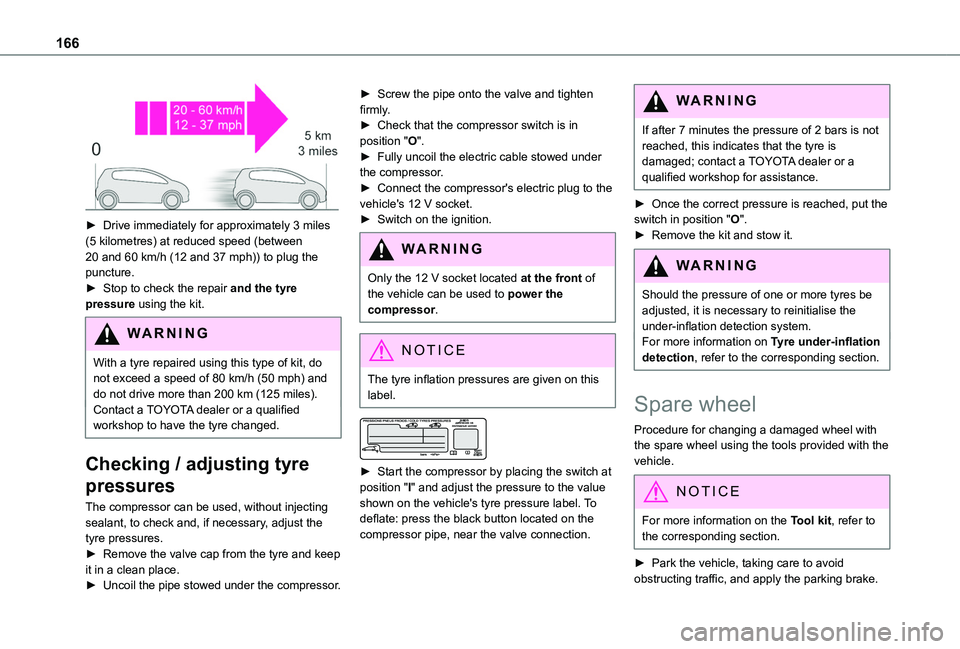
► Drive immediately for approximately 3 miles (5 kilometres) at reduced speed (between 20 and 60 km/h (12 and 37 mph)) to plug the puncture.► Stop to check the repair and the tyre pressure using the kit.
WARNI NG
With a tyre repaired using this type of kit, do not exceed a speed of 80 km/h (50 mph) and do not drive more than 200 km (125 miles).Contact a TOYOTA dealer or a qualified workshop to have the tyre changed.
Checking / adjusting tyre
pressures
The compressor can be used, without injecting sealant, to check and, if necessary, adjust the tyre pressures.► Remove the valve cap from the tyre and keep it in a clean place.► Uncoil the pipe stowed under the compressor.
► Screw the pipe onto the valve and tighten firmly.► Check that the compressor switch is in position "O".► Fully uncoil the electric cable stowed under the compressor.► Connect the compressor's electric plug to the vehicle's 12 V socket.► Switch on the ignition.
WARNI NG
Only the 12 V socket located at the front of the vehicle can be used to power the compressor.
NOTIC E
The tyre inflation pressures are given on this label.
► Start the compressor by placing the switch at position "I" and adjust the pressure to the value shown on the vehicle's tyre pressure label. To deflate: press the black button located on the compressor pipe, near the valve connection.
WARNI NG
If after 7 minutes the pressure of 2 bars is not reached, this indicates that the tyre is damaged; contact a TOYOTA dealer or a qualified workshop for assistance.
► Once the correct pressure is reached, put the switch in position "O".► Remove the kit and stow it.
WARNI NG
Should the pressure of one or more tyres be adjusted, it is necessary to reinitialise the under-inflation detection system.For more information on Tyre under-inflation detection, refer to the corresponding section.
Spare wheel
Procedure for changing a damaged wheel with
the spare wheel using the tools provided with the vehicle.
NOTIC E
For more information on the Tool kit, refer to the corresponding section.
► Park the vehicle, taking care to avoid obstructing traffic, and apply the parking brake.