bulb TOYOTA RAV4 1996 Service Owner's Manual
[x] Cancel search | Manufacturer: TOYOTA, Model Year: 1996, Model line: RAV4, Model: TOYOTA RAV4 1996Pages: 1632, PDF Size: 41.64 MB
Page 911 of 1632
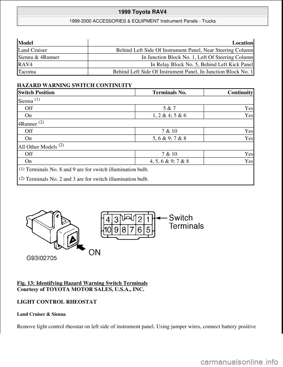
HAZARD WARNING SWITCH CONTINUITY
Fig. 13: Identifying Hazard Warning Switch Terminals
Courtesy of TOYOTA MOTOR SALES, U.S.A., INC.
LIGHT CONTROL RHEOSTAT
Land Cruiser & Sienna
Remove light control rheostat on left side of instrument panel. Using jumper wires, connect battery positive
ModelLocation
Land CruiserBehind Left Side Of Instrument Panel, Near Steering Column
Sienna & 4RunnerIn Junction Block No. 1, Left Of Steering Column
RAV4In Relay Block No. 5, Behind Left Kick Panel
TacomaBehind Left Side Of Instrument Panel, In Junction Block No. 1
Switch PositionTerminals No.Continuity
Sienna (1)
Off5 & 7Yes
On1, 2 & 4; 5 & 6Yes
4Runner (2)
Off7 & 10Yes
On5, 6 & 9; 7 & 8Yes
All Other Models (2)
Off7 & 10Yes
On4, 5, 6 & 9; 7 & 8Yes
(1)Terminals No. 8 and 9 are for switch illumination bulb.
(2)Terminals No. 2 and 3 are for switch illumination bulb.
1999 Toyota RAV4
1999-2000 ACCESSORIES & EQUIPMENT Instrument Panels - Trucks
Microsoft
Sunday, November 22, 2009 10:54:10 AMPage 21 © 2005 Mitchell Repair Information Company, LLC.
Page 914 of 1632
LOW OIL PRESSURE WARNING LIGHT
RAV4, Sienna, Tacoma, Tundra Without Tachometer & 4Runner
Disconnect low oil pressure switch connector. See OIL PRESSURE SWITCH LOCATION table. Using a
jumper wire, connect low oil pressure switch connector terminal to ground. Turn ignition switch to ON position.
Low oil pressure warning light should turn on. If low oil pressure warning light is off, check bulb or inspect
wiring harness.
OCCUPANT DETECTION SENSOR
Land Cruiser & Tundra
Disconnect occupant detection sensor connector, located under passenger seat. Check continuity between sensor
connector terminals. Continuity should exist only when pressing on sensor. If continuity is not as specified,
replace occupant detection sensor.
OIL PRESSURE GAUGE & SENDER
Oil Pressure Gauge & Harness Operational Test (Land Cruiser & Tundra With Tachometer)
1. Disconnect oil pressure sender connector. See OIL PRESSURE SENDER LOCATION table. Turn
ignition switch to ON position. Oil gauge should indicate LOW. Turn ignition switch to OFF position.
Connect a 12-volt, 3.4-watt test light between oil sending unit harness connector terminal and ground.
2. Turn ignition switch to ON position. Test light should be on and oil pressure gauge should slowly move
to HIGH. If gauge functions as specified, perform OIL PRESSURE SENDER OPERATIONAL
TEST . If gauge does not function as specified, perform OIL PRESSURE GAUGE RESISTANCE
TEST .
Oil Pressure Sender Operational Test (Land Cruiser & Tundra With Tachometer)
Disconnect oil pressure sender connector. See OIL PRESSURE SENDER LOCATION table. Using 12-volt
source, connect an LED tester between positive battery terminal and oil pressure sender terminal. With engine
off, LED should be off. With engine running, LED should flash. LED flashes will vary with engine speed and
oil pressure. Replace oil pressure sender if LED does not operate as specified.
OIL PRESSURE SENDER LOCATION
Oil Pressure Gauge Resistance Test (Land Cruiser & Tundra With Tachometer)
Remove instrument cluster. See INSTRUMENT CLUSTER under REMOVAL & INSTALLATION. Using
an ohmmeter, check resistance between oil gauge terminals on rear of instrument cluster. See Fig. 16
or Fig.
17 . See OIL PRESSURE GAUGE RESISTANCE SPECIFICATIONS table. If resistance is not as
specified, replace oil pressure
gauge.
ApplicationLocation
Land Cruiser & TundraOn Oil Filter Housing
1999 Toyota RAV4
1999-2000 ACCESSORIES & EQUIPMENT Instrument Panels - Trucks
Microsoft
Sunday, November 22, 2009 10:54:10 AMPage 24 © 2005 Mitchell Repair Information Company, LLC.
Page 916 of 1632
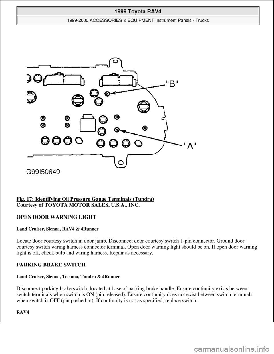
Fig. 17: Identifying Oil Pressure Gauge Terminals (Tundra)
Courtesy of TOYOTA MOTOR SALES, U.S.A., INC.
OPEN DOOR WARNING LIGHT
Land Cruiser, Sienna, RAV4 & 4Runner
Locate door courtesy switch in door jamb. Disconnect door courtesy switch 1-pin connector. Ground door
courtesy switch wiring harness connector terminal. Open door warning light should be on. If open door warning
light is off, check bulb and wiring harness. Repair as necessary.
PARKING BRAKE SWITCH
Land Cruiser, Sienna, Tacoma, Tundra & 4Runner
Disconnect parking brake switch, located at base of parking brake handle. Ensure continuity exists between
switch terminals when switch is ON (pin released). Ensure continuity does not exist between switch terminals
when switch is OFF (pin pushed in). If continuity is not as specified, replace switch.
RAV4
1999 Toyota RAV4
1999-2000 ACCESSORIES & EQUIPMENT Instrument Panels - Trucks
Microsoft
Sunday, November 22, 2009 10:54:10 AMPage 26 © 2005 Mitchell Repair Information Company, LLC.
Page 918 of 1632
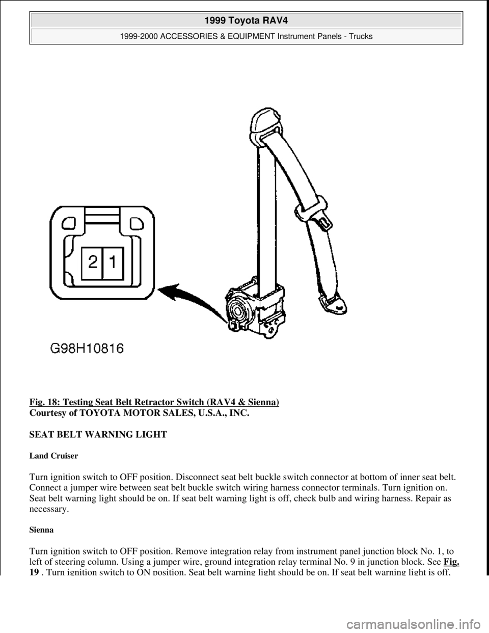
Fig. 18: Testing Seat Belt Retractor Switch (RAV4 & Sienna)
Courtesy of TOYOTA MOTOR SALES, U.S.A., INC.
SEAT BELT WARNING LIGHT
Land Cruiser
Turn ignition switch to OFF position. Disconnect seat belt buckle switch connector at bottom of inner seat belt.
Connect a jumper wire between seat belt buckle switch wiring harness connector terminals. Turn ignition on.
Seat belt warning light should be on. If seat belt warning light is off, check bulb and wiring harness. Repair as
necessary.
Sienna
Turn ignition switch to OFF position. Remove integration relay from instrument panel junction block No. 1, to
left of steering column. Using a jumper wire, ground integration relay terminal No. 9 in junction block. See Fi
g.
19 . Turn ignition switch to ON position. Seat belt warning light should be on. If seat belt warning light is off,
1999 Toyota RAV4
1999-2000 ACCESSORIES & EQUIPMENT Instrument Panels - Trucks
Microsoft
Sunday, November 22, 2009 10:54:10 AMPage 28 © 2005 Mitchell Repair Information Company, LLC.
Page 919 of 1632
check bulb and wiring harness. Repair as necessary.
SEAT BELT WARNING SYSTEM
Integration Relay Operation (Sienna)
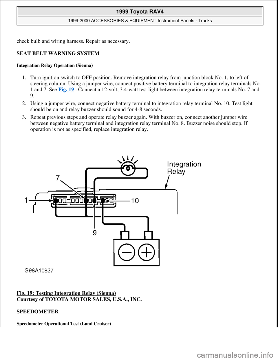
1. Turn ignition switch to OFF position. Remove integration relay from junction block No. 1, to left of
steering column. Using a jumper wire, connect positive battery terminal to integration relay terminals No.
1 and 7. See Fig. 19
. Connect a 12-volt, 3.4-watt test light between integration relay terminals No. 7 and
9.
2. Using a jumper wire, connect negative battery terminal to integration relay terminal No. 10. Test light
should be on and relay buzzer should sound for 4-8 seconds.
3. Repeat previous steps and operate relay buzzer again. With buzzer on, connect another jumper wire
between negative battery terminal and integration relay terminal No. 8. Buzzer noise should stop. If
operation is not as specified, replace integration relay.
Fig. 19: Testing Integration Relay (Sienna)
Courtesy of TOYOTA MOTOR SALES, U.S.A., INC.
SPEEDOMETER
Speedometer Operational Test (Land Cruiser)
1999 Toyota RAV4
1999-2000 ACCESSORIES & EQUIPMENT Instrument Panels - Trucks
Microsoft
Sunday, November 22, 2009 10:54:10 AMPage 29 © 2005 Mitchell Repair Information Company, LLC.
Page 923 of 1632
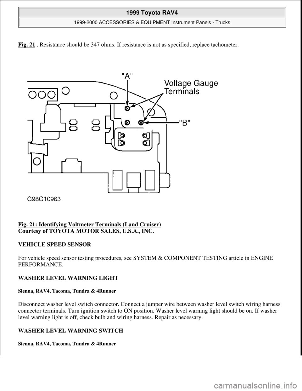
Fig. 21 . Resistance should be 347 ohms. If resistance is not as specified, replace tachometer.
Fig. 21: Identifying Voltmeter Terminals (Land Cruiser)
Courtesy of TOYOTA MOTOR SALES, U.S.A., INC.
VEHICLE SPEED SENSOR
For vehicle speed sensor testing procedures, see SYSTEM & COMPONENT TESTING article in ENGINE
PERFORMANCE.
WASHER LEVEL WARNING LIGHT
Sienna, RAV4, Tacoma, Tundra & 4Runner
Disconnect washer level switch connector. Connect a jumper wire between washer level switch wiring harness
connector terminals. Turn ignition switch to ON position. Washer level warning light should be on. If washer
level warning light is off, check bulb and wiring harness. Repair as necessary.
WASHER LEVEL WARNING SWITCH
Sienna, RAV4, Tacoma, Tundra & 4Runner
1999 Toyota RAV4
1999-2000 ACCESSORIES & EQUIPMENT Instrument Panels - Trucks
Microsoft
Sunday, November 22, 2009 10:54:10 AMPage 33 © 2005 Mitchell Repair Information Company, LLC.
Page 951 of 1632
ELECTROSTATIC DISCHARGE SENSITIVE (ESD) PARTS
ENGINE OIL
FUEL SYSTEM SERVICE
HALOGEN BULBS
RADIATOR CAP
RADIATOR FAN
WARRANTY INFORMATION
NEW VEHICLE LIMITED WARRANTY WARNING:Many solid state electrical components can be damaged by static
electricity (ESD). Some will display a warning label, but many will not.
Discharge personal static electricity by touching a metal ground point on
the vehicle prior to servicing any ESD sensitive component.
CAUTION: Never use non-detergent or straight mineral oil.
WARNING:Relieve fuel system pressure prior to servicing any fuel system
component (fuel injection models).
WARNING:Halogen bulbs contain pressurized gas which may explode if overheated.
DO NOT touch glass portion of bulb with bare hands. Eye protection
should be worn when handling or working around halogen bulbs.
CAUTION: Always disconnect the fan motor when working near the radiator fan. The
fan is temperature controlled and could start at any time even when the
ignition key is in the OFF position. DO NOT loosen or remove radiator cap
when cooling system is hot.
WARNING:Keep hands away from radiator fan. Fan is controlled by a thermostatic
switch which may come on or run for up to 15 minutes even after engine
is turned off.
CAUTION: Due to the different warranties offered in various regions and the variety of
after-market extended warranties available, please refer to the warranty
package that came with the vehicle to verify all warranty options.
1999 Toyota RAV4
MAINTENANCE INFORMATION 1997-99 MAINTENANCE Toyota Maintenance Information
Microsoft
Sunday, November 22, 2009 10:32:42 AMPage 9 © 2005 Mitchell Repair Information Company, LLC.
Page 1208 of 1632
1999-2000 STEERING
Steering Columns - Standard
DESCRIPTION & OPERATION
Steering column is a collapsible 2-piece design. Columns use shear pins to absorb collision impact. Steering
shaft is connected directly to steering gear with either a flexible coupling or "U" joint. Some models have an air
bag integral with the steering wheel pad.
SERVICE PRECAUTIONS
Observe the following precautions when servicing Supplemental Restraint System (SRS):
Disable SRS before servicing any SRS or steering column component. Failure to do this could result in
accidental air bag deployment and possible personal injury. See DISABLING & ACTIVATING AIR
BAG SYSTEM .
Remove air bag sensor assembly/center air bag sensor and front air bag sensors if repairing the vehicle
requires impacting (shocking) the vehicle.
Replace dropped, cracked, dented or otherwise damaged components.
DO NOT expose front air bag sensors, air bag sensor assembly/center air bag sensor or steering wheel
pad (air bag module) directly to heat or flame.
Information labels are attached to air bag components. Follow all notices on labels.
After work on SRS is completed, check air bag warning light to ensure system is functioning properly.
See appropriate AIR BAG RESTRAINT SYSTEMS article in ACCESSORIES & EQUIPMENT.
Always wear safety glasses when servicing or handling an air bag.
When placing a live air bag on a bench or other surface, always face air bag and trim cover upward, away
from surface. This will reduce motion of module if it is accidentally deployed.
Carry a live air bag module with trim cover (air bag) pointed away from your body to minimize injury in
case of accidental deployment.
If SRS is not fully functional for any reason, vehicle should not be driven until system is repaired and
becomes operational. DO NOT remove bulbs, modules, sensors or other components or in any way
disable system from operating normally. If SRS is not functional, park vehicle until it is repaired and
functions properl
y. NOTE: For models with tilt wheel steering columns, see appropriate STEERING
COLUMNS - TILT WHEEL article.
WARNING:To avoid injury from accidental air bag deployment, read and carefully
follow all SERVICE PRECAUTIONS. Deactivate air bag system before
performing any repairs. See DISABLING & ACTIVATING AIR BAG
SYSTEM .
1999 Toyota RAV4
1999-2000 STEERING Steering Columns - Standard
1999 Toyota RAV4
1999-2000 STEERING Steering Columns - Standard
Microsoft
Sunday, November 22, 2009 10:34:51 AMPage 1 © 2005 Mitchell Repair Information Company, LLC.
Microsoft
Sunday, November 22, 2009 10:34:55 AMPage 1 © 2005 Mitchell Repair Information Company, LLC.
Page 1236 of 1632
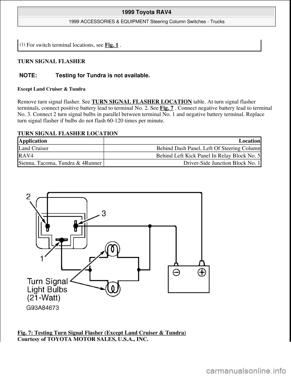
TURN SIGNAL FLASHER
Except Land Cruiser & Tundra
Remove turn signal flasher. See TURN SIGNAL FLASHER LOCATION table. At turn signal flasher
terminals, connect positive battery lead to terminal No. 2. See Fig. 7
. Connect negative battery lead to terminal
No. 3. Connect 2 turn signal bulbs in parallel between terminal No. 1 and negative battery terminal. Replace
turn signal flasher if bulbs do not flash 60-120 times per minute.
TURN SIGNAL FLASHER LOCATION
Fig. 7: Testing Turn Signal Flasher (Except Land Cruiser & Tundra)
Courtesy of TOYOTA MOTOR SALES, U.S.A., INC.
(1)For switch terminal locations, see Fig. 1 .
NOTE: Testing for Tundra is not available.
ApplicationLocation
Land CruiserBehind Dash Panel, Left Of Steering Column
RAV4Behind Left Kick Panel In Relay Block No. 5
Sienna, Tacoma, Tundra & 4RunnerDriver-Side Junction Block No. 1
1999 Toyota RAV4
1999 ACCESSORIES & EQUIPMENT Steering Column Switches - Trucks
Microsoft
Sunday, November 22, 2009 10:56:55 AMPage 8 © 2005 Mitchell Repair Information Company, LLC.
Page 1255 of 1632
1999-2000 STEERING
Steering Columns - Tilt Wheel - Trucks & Vans
DESCRIPTION & OPERATION
Tilt steering columns incorporate a main shaft, attached by a "U" joint to an intermediate steering shaft. Shafts
are held in place by upper and lower column tubes. Column tubes are pinned together so upper column can
move up or down. Upper column is locked in place by pawl attached to lever. Steering columns are collapsible.
SERVICE PRECAUTIONS
Observe the following precautions when servicing SRS:
Disable SRS before servicing any SRS or steering column component. Failure to do this could result in
accidental air bag deployment and possible personal injury. See DISABLING & ACTIVATING AIR
BAG SYSTEM .
Remove air bag sensor assembly/center air bag sensor and front air bag sensors if repairing the vehicle
requires impacting (shocking) the vehicle.
Replace dropped, cracked, dented or otherwise damaged components.
DO NOT expose front air bag sensors, air bag sensor assembly/center air bag sensor or steering wheel
pad (air bag module) directly to heat or flame.
Information labels are attached to air bag components. Follow all notices on labels.
After work on SRS is completed, check air bag warning light to ensure system is functioning properly.
See appropriate AIR BAG RESTRAINT SYSTEMS article in ACCESSORIES & EQUIPMENT.
Always wear safety glasses when servicing or handling an air bag.
When placing a live air bag on a bench or other surface, always face air bag and trim cover upward, away
from surface. This will reduce motion of module if it is accidentally deployed.
Carry a live air bag module with trim cover (air bag) pointed away from your body to minimize injury in
case of accidental deployment.
If SRS is not fully functional for any reason, vehicle should not be driven until system is repaired and
becomes operational. DO NOT remove bulbs, modules, sensors or other components or in any way
disable system from operating normally. If SRS is not functional, park vehicle until it is repaired and
functions properly.
DISABLING & ACTIVATING AIR BAG SYSTEM
WARNING:To avoid injury from accidental air bag deployment, read and carefully
follow all SERVICE PRECAUTIONS
. Deactivate air bag system before
performing any repairs. See DISABLING & ACTIVATING AIR BAG
SYSTEM .
WARNING:Back-up power supply maintains SRS voltage for about 90 seconds after
1999 Toyota RAV4
1999-2000 STEERING Steering Columns - Tilt Wheel - Trucks & Vans
1999 Toyota RAV4
1999-2000 STEERING Steering Columns - Tilt Wheel - Trucks & Vans
Microsoft
Sunday, November 22, 2009 10:34:02 AMPage 1 © 2005 Mitchell Repair Information Company, LLC.
Microsoft
Sunday, November 22, 2009 10:34:07 AMPage 1 © 2005 Mitchell Repair Information Company, LLC.