roof TOYOTA RAV4 1996 Service Repair Manual
[x] Cancel search | Manufacturer: TOYOTA, Model Year: 1996, Model line: RAV4, Model: TOYOTA RAV4 1996Pages: 1632, PDF Size: 41.64 MB
Page 17 of 1632
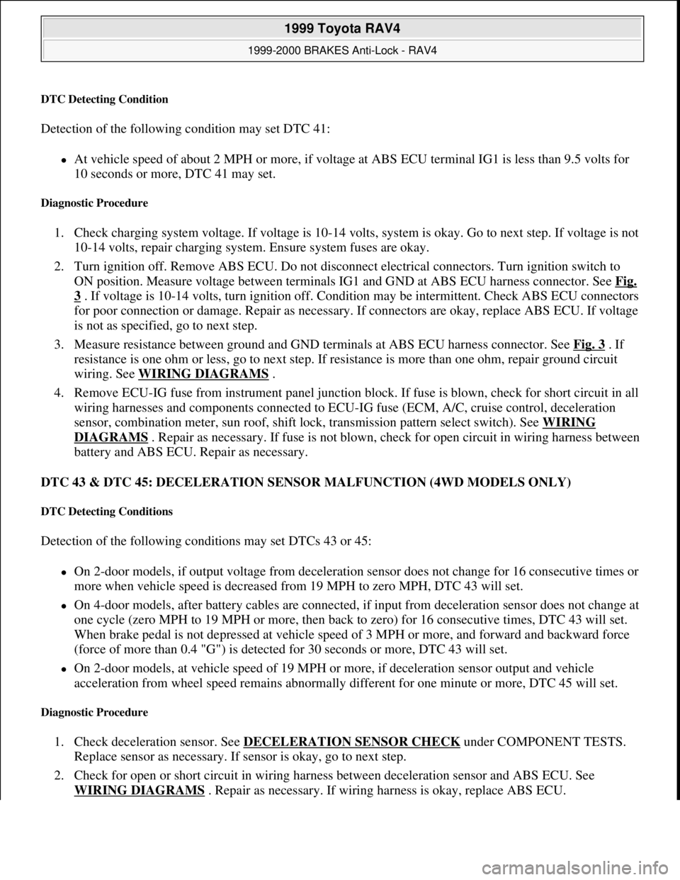
DTC Detecting Condition
Detection of the following condition may set DTC 41:
At vehicle speed of about 2 MPH or more, if voltage at ABS ECU terminal IG1 is less than 9.5 volts for
10 seconds or more, DTC 41 may set.
Diagnostic Procedure
1. Check charging system voltage. If voltage is 10-14 volts, system is okay. Go to next step. If voltage is not
10-14 volts, repair charging system. Ensure system fuses are okay.
2. Turn ignition off. Remove ABS ECU. Do not disconnect electrical connectors. Turn ignition switch to
ON position. Measure voltage between terminals IG1 and GND at ABS ECU harness connector. See Fig.
3 . If voltage is 10-14 volts, turn ignition off. Condition may be intermittent. Check ABS ECU connectors
for poor connection or damage. Repair as necessary. If connectors are okay, replace ABS ECU. If voltage
is not as specified, go to next step.
3. Measure resistance between ground and GND terminals at ABS ECU harness connector. See Fig. 3
. If
resistance is one ohm or less, go to next step. If resistance is more than one ohm, repair ground circuit
wiring. See WIRING DIAGRAMS
.
4. Remove ECU-IG fuse from instrument panel junction block. If fuse is blown, check for short circuit in all
wiring harnesses and components connected to ECU-IG fuse (ECM, A/C, cruise control, deceleration
sensor, combination meter, sun roof, shift lock, transmission pattern select switch). See WIRING
DIAGRAMS . Repair as necessary. If fuse is not blown, check for open circuit in wiring harness between
battery and ABS ECU. Repair as necessary.
DTC 43 & DTC 45: DECELERATION SENSOR MALFUNCTION (4WD MODELS ONLY)
DTC Detecting Conditions
Detection of the following conditions may set DTCs 43 or 45:
On 2-door models, if output voltage from deceleration sensor does not change for 16 consecutive times or
more when vehicle speed is decreased from 19 MPH to zero MPH, DTC 43 will set.
On 4-door models, after battery cables are connected, if input from deceleration sensor does not change at
one cycle (zero MPH to 19 MPH or more, then back to zero) for 16 consecutive times, DTC 43 will set.
When brake pedal is not depressed at vehicle speed of 3 MPH or more, and forward and backward force
(force of more than 0.4 "G") is detected for 30 seconds or more, DTC 43 will set.
On 2-door models, at vehicle speed of 19 MPH or more, if deceleration sensor output and vehicle
acceleration from wheel speed remains abnormally different for one minute or more, DTC 45 will set.
Diagnostic Procedure
1. Check deceleration sensor. See DECELERATION SENSOR CHECK under COMPONENT TESTS.
Replace sensor as necessary. If sensor is okay, go to next step.
2. Check for open or short circuit in wiring harness between deceleration sensor and ABS ECU. See
WIRING DIAGRAMS
. Repair as necessary. If wiring harness is okay, replace ABS ECU.
1999 Toyota RAV4
1999-2000 BRAKES Anti-Lock - RAV4
Microsoft
Sunday, November 22, 2009 10:06:17 AMPage 17 © 2005 Mitchell Repair Information Company, LLC.
Page 82 of 1632
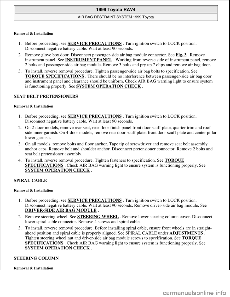
Removal & Installation
1. Before proceeding, see SERVICE PRECAUTIONS . Turn ignition switch to LOCK position.
Disconnect negative battery cable. Wait at least 90 seconds.
2. Remove glove box door. Disconnect passenger-side air bag module connector. See Fig. 3
. Remove
instrument panel. See INSTRUMENT PANEL
. Working from reverse side of instrument panel, remove
2 bolts and passenger-side air bag module. Remove 3 bolts and pry up 7 clips and remove air bag door.
3. To install, reverse removal procedure. Tighten passenger-side air bag bolts to specification. See
TORQUE SPECIFICATIONS
. There should be no interference between passenger-side air bag door
and instrument panel and clearance should be uniform. Check AIR BAG warning light to ensure system
is functioning properly. See SYSTEM OPERATION CHECK
.
SEAT BELT PRETENSIONERS
Removal & Installation
1. Before proceeding, see SERVICE PRECAUTIONS . Turn ignition switch to LOCK position.
Disconnect negative battery cable. Wait at least 90 seconds.
2. On 2-door models, remove rear seat, rear floor finish panel front door scuff plate, quarter trim and roof
side inner garnish. On 4-door models, remove rear door scuff plate, front door scuff plate and center pillar
lower garnish.
3. On all models, remove bolts and floor anchor. Tape tip of screwdriver and remove seat belt assembly
anchor caps. Remove bolt and shoulder anchor. Disconnect pretensioner connector. Remove 2 bolts and
seat belt pretensioner assembly.
4. To install, reverse removal procedure. Tighten fasteners to specification. See TORQUE
SPECIFICATIONS . Check AIR BAG warning light to ensure system is functioning properly. See
SYSTEM OPERATION CHECK
.
SPIRAL CABLE
Removal & Installation
1. Before proceeding, see SERVICE PRECAUTIONS . Turn ignition switch to LOCK position.
Disconnect negative battery cable. Wait at least 90 seconds. Remove driver-side air bag module. See
DRIVER
-SIDE AIR BAG MODULE .
2. Remove steering wheel. See STEERING WHEEL
. Remove lower steering column cover. Disconnect
lower spiral cable connector. Remove 4 screws and spiral cable.
3. To install, reverse removal procedure. Before installing spiral cable, ensure front wheels are in straight-
ahead position and spiral cable is properly aligned. See SPIRAL CABLE under ADJUSTMENTS
.
Tighten steering wheel nut and driver-side air bag module screws to specification. See TORQUE
SPECIFICATIONS . Check AIR BAG warning light to ensure system is functioning properly. See
SYSTEM OPERATION CHECK
.
STEERING COLUMN
Removal & Installation
1999 Toyota RAV4
AIR BAG RESTRAINT SYSTEM 1999 Toyota
Microsoft
Sunday, November 22, 2009 10:33:22 AMPage 19 © 2005 Mitchell Repair Information Company, LLC.
Page 674 of 1632
1999 TOYOTA
RAV4
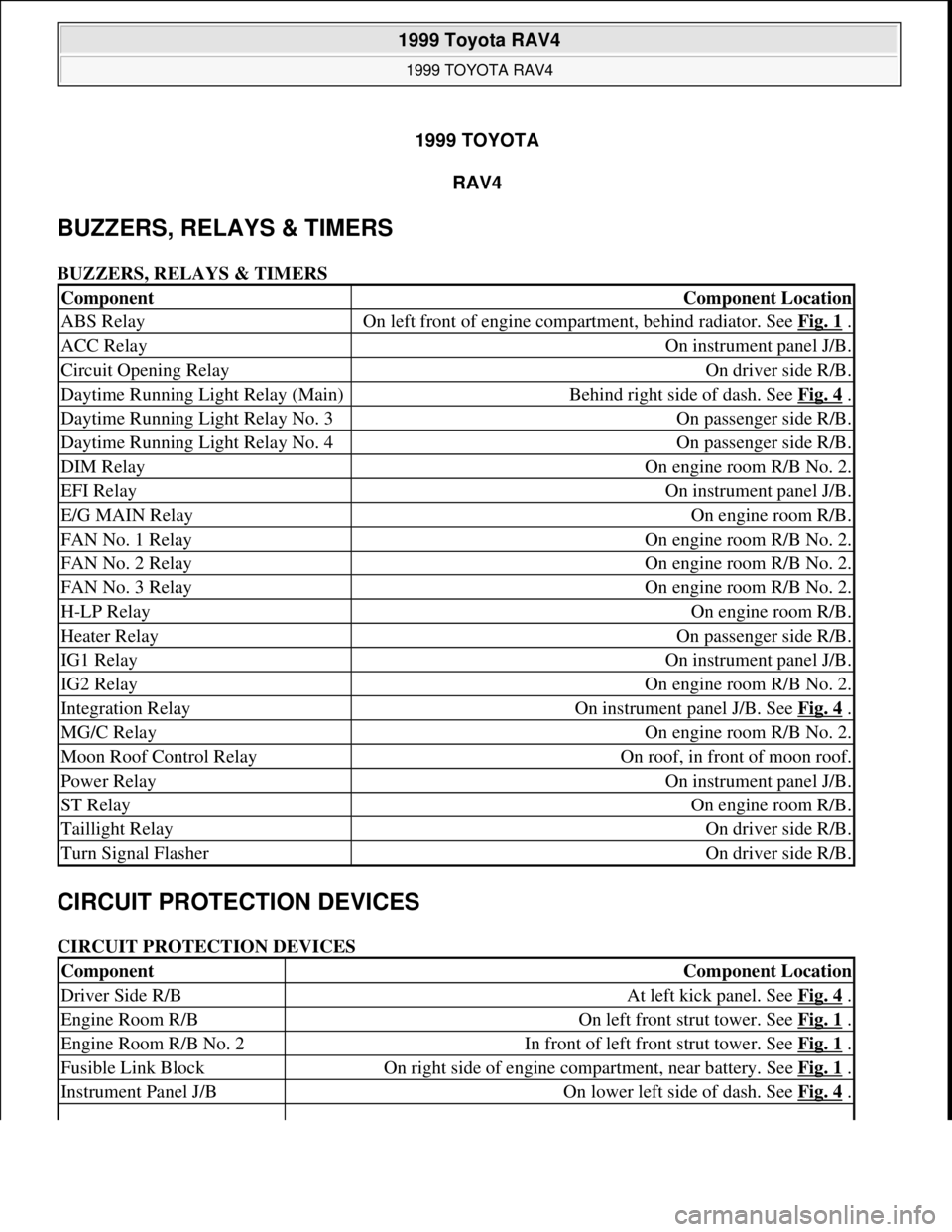
BUZZERS, RELAYS & TIMERS
BUZZERS, RELAYS & TIMERS
CIRCUIT PROTECTION DEVICES
CIRCUIT PROTECTION DEVICES
ComponentComponent Location
ABS RelayOn left front of engine compartment, behind radiator. See Fig. 1 .
ACC RelayOn instrument panel J/B.
Circuit Opening RelayOn driver side R/B.
Daytime Running Light Relay (Main)Behind right side of dash. See Fig. 4 .
Daytime Running Light Relay No. 3On passenger side R/B.
Daytime Running Light Relay No. 4On passenger side R/B.
DIM RelayOn engine room R/B No. 2.
EFI RelayOn instrument panel J/B.
E/G MAIN RelayOn engine room R/B.
FAN No. 1 RelayOn engine room R/B No. 2.
FAN No. 2 RelayOn engine room R/B No. 2.
FAN No. 3 RelayOn engine room R/B No. 2.
H-LP RelayOn engine room R/B.
Heater RelayOn passenger side R/B.
IG1 RelayOn instrument panel J/B.
IG2 RelayOn engine room R/B No. 2.
Integration RelayOn instrument panel J/B. See Fig. 4 .
MG/C RelayOn engine room R/B No. 2.
Moon Roof Control RelayOn roof, in front of moon roof.
Power RelayOn instrument panel J/B.
ST RelayOn engine room R/B.
Taillight RelayOn driver side R/B.
Turn Signal FlasherOn driver side R/B.
ComponentComponent Location
Driver Side R/BAt left kick panel. See Fig. 4 .
Engine Room R/BOn left front strut tower. See Fig. 1 .
Engine Room R/B No. 2In front of left front strut tower. See Fig. 1 .
Fusible Link BlockOn right side of engine compartment, near battery. See Fig. 1 .
Instrument Panel J/BOn lower left side of dash. See Fig. 4 .
1999 Toyota RAV4
1999 TOYOTA RAV4
1999 Toyota RAV4
1999 TOYOTA RAV4
Microsoft
Sunday, November 22, 2009 10:17:32 AMPage 1 © 2005 Mitchell Repair Information Company, LLC.
Microsoft
Sunday, November 22, 2009 10:17:35 AMPage 1 © 2005 Mitchell Repair Information Company, LLC.
Page 675 of 1632
CONTROL UNITS
CONTROL UNITS
MOTORS
MOTORS
SENDING UNITS & SENSORS
SENDING UNITS & SENSORS
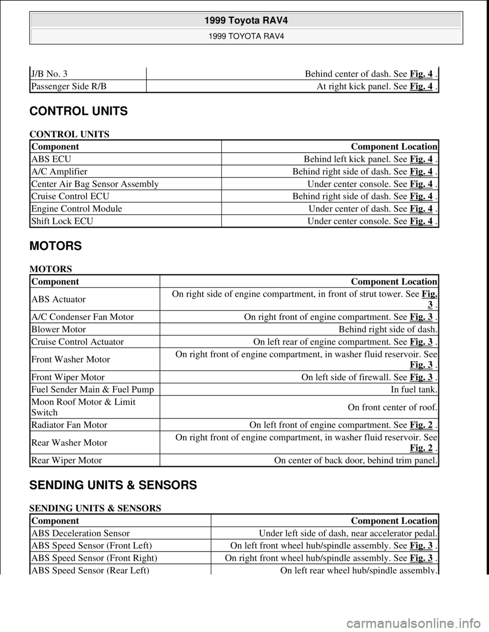
J/B No. 3Behind center of dash. See Fig. 4 .
Passenger Side R/BAt right kick panel. See Fig. 4 .
ComponentComponent Location
ABS ECUBehind left kick panel. See Fig. 4 .
A/C AmplifierBehind right side of dash. See Fig. 4 .
Center Air Bag Sensor AssemblyUnder center console. See Fig. 4 .
Cruise Control ECUBehind right side of dash. See Fig. 4 .
Engine Control ModuleUnder center of dash. See Fig. 4 .
Shift Lock ECUUnder center console. See Fig. 4 .
ComponentComponent Location
ABS ActuatorOn right side of engine compartment, in front of strut tower. See Fig.
3 .
A/C Condenser Fan MotorOn right front of engine compartment. See Fig. 3 .
Blower MotorBehind right side of dash.
Cruise Control ActuatorOn left rear of engine compartment. See Fig. 3 .
Front Washer MotorOn right front of engine compartment, in washer fluid reservoir. See
Fig. 3
.
Front Wiper MotorOn left side of firewall. See Fig. 3 .
Fuel Sender Main & Fuel PumpIn fuel tank.
Moon Roof Motor & Limit
SwitchOn front center of roof.
Radiator Fan MotorOn left front of engine compartment. See Fig. 2 .
Rear Washer MotorOn right front of engine compartment, in washer fluid reservoir. See
Fig. 2
.
Rear Wiper MotorOn center of back door, behind trim panel.
ComponentComponent Location
ABS Deceleration SensorUnder left side of dash, near accelerator pedal.
ABS Speed Sensor (Front Left)On left front wheel hub/spindle assembly. See Fig. 3 .
ABS Speed Sensor (Front Right)On right front wheel hub/spindle assembly. See Fig. 3 .
ABS Speed Sensor (Rear Left)On left rear wheel hub/spindle assembly.
1999 Toyota RAV4
1999 TOYOTA RAV4
Microsoft
Sunday, November 22, 2009 10:17:32 AMPage 2 © 2005 Mitchell Repair Information Company, LLC.
Page 679 of 1632
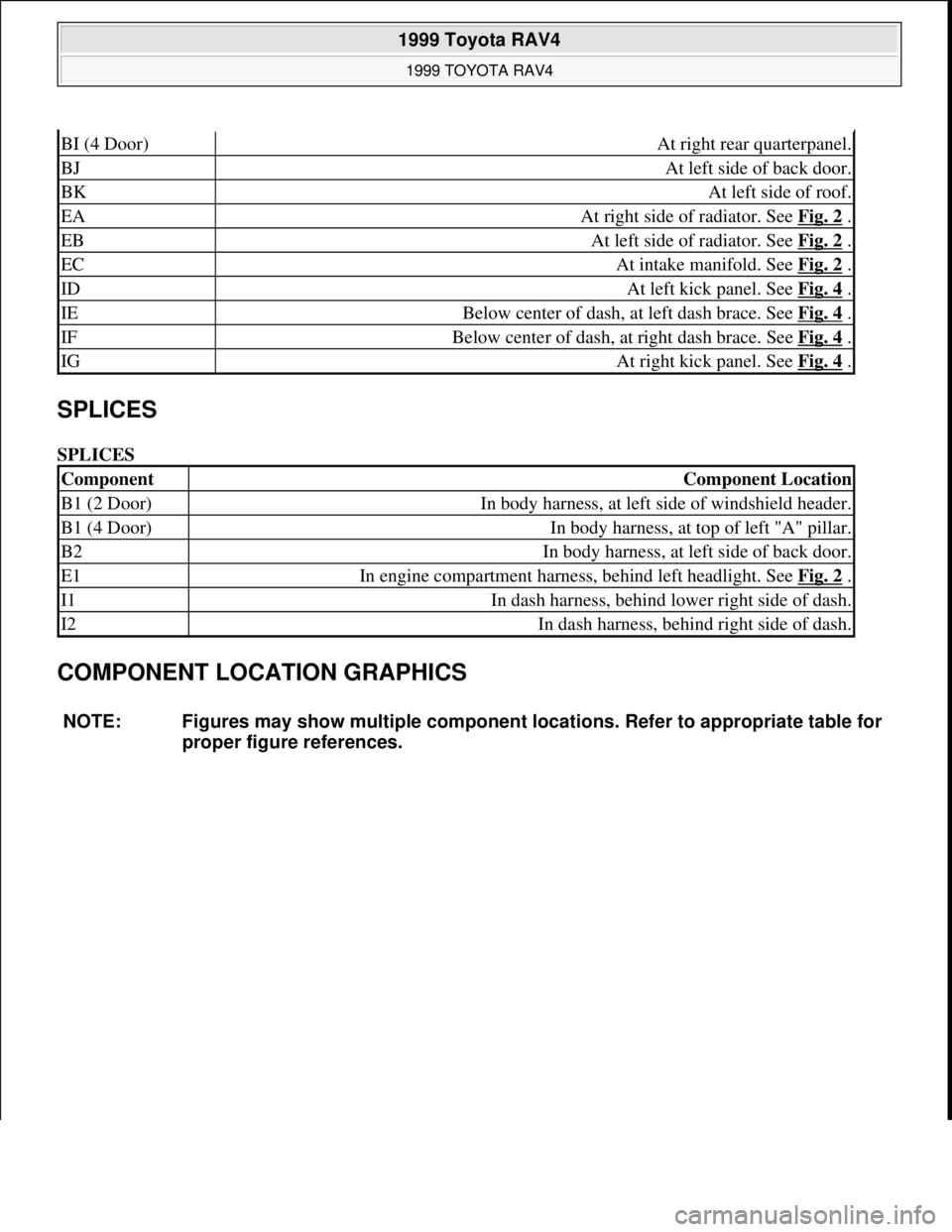
SPLICES
SPLICES
COMPONENT LOCATION GRAPHICS
BI (4 Door)At right rear quarterpanel.
BJAt left side of back door.
BKAt left side of roof.
EAAt right side of radiator. See Fig. 2 .
EBAt left side of radiator. See Fig. 2 .
ECAt intake manifold. See Fig. 2 .
IDAt left kick panel. See Fig. 4 .
IEBelow center of dash, at left dash brace. See Fig. 4 .
IFBelow center of dash, at right dash brace. See Fig. 4 .
IGAt right kick panel. See Fig. 4 .
ComponentComponent Location
B1 (2 Door)In body harness, at left side of windshield header.
B1 (4 Door)In body harness, at top of left "A" pillar.
B2In body harness, at left side of back door.
E1In engine compartment harness, behind left headlight. See Fig. 2 .
I1In dash harness, behind lower right side of dash.
I2In dash harness, behind right side of dash.
NOTE: Figures may show multiple component locations. Refer to appropriate table for
proper figure references.
1999 Toyota RAV4
1999 TOYOTA RAV4
Microsoft
Sunday, November 22, 2009 10:17:32 AMPage 6 © 2005 Mitchell Repair Information Company, LLC.
Page 969 of 1632
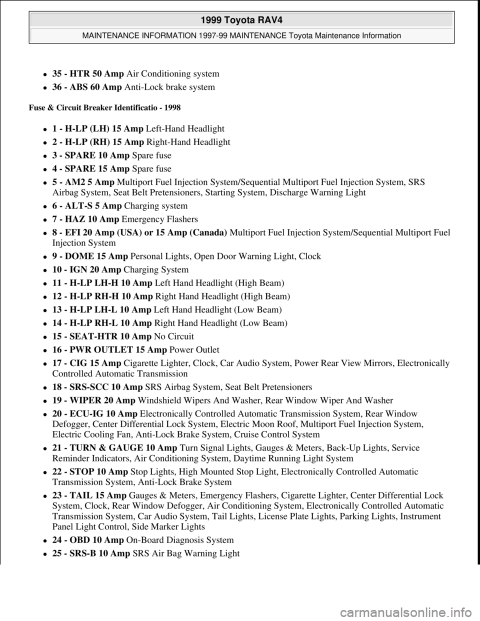
35 - HTR 50 Amp Air Conditioning system
36 - ABS 60 Amp Anti-Lock brake system
Fuse & Circuit Breaker Identificatio - 1998
1 - H-LP (LH) 15 Amp Left-Hand Headlight
2 - H-LP (RH) 15 Amp Right-Hand Headlight
3 - SPARE 10 Amp Spare fuse
4 - SPARE 15 Amp Spare fuse
5 - AM2 5 Amp Multiport Fuel Injection System/Sequential Multiport Fuel Injection System, SRS
Airbag System, Seat Belt Pretensioners, Starting System, Discharge Warning Light
6 - ALT-S 5 Amp Charging system
7 - HAZ 10 Amp Emergency Flashers
8 - EFI 20 Amp (USA) or 15 Amp (Canada)Multiport Fuel Injection System/Sequential Multiport Fuel
Injection System
9 - DOME 15 Amp Personal Lights, Open Door Warning Light, Clock
10 - IGN 20 Amp Charging System
11 - H-LP LH-H 10 Amp Left Hand Headlight (High Beam)
12 - H-LP RH-H 10 Amp Right Hand Headlight (High Beam)
13 - H-LP LH-L 10 Amp Left Hand Headlight (Low Beam)
14 - H-LP RH-L 10 Amp Right Hand Headlight (Low Beam)
15 - SEAT-HTR 10 Amp No Circuit
16 - PWR OUTLET 15 Amp Power Outlet
17 - CIG 15 Amp Cigarette Lighter, Clock, Car Audio System, Power Rear View Mirrors, Electronically
Controlled Automatic Transmission
18 - SRS-SCC 10 Amp SRS Airbag System, Seat Belt Pretensioners
19 - WIPER 20 Amp Windshield Wipers And Washer, Rear Window Wiper And Washer
20 - ECU-IG 10 Amp Electronically Controlled Automatic Transmission System, Rear Window
Defogger, Center Differential Lock System, Electric Moon Roof, Multiport Fuel Injection System,
Electric Cooling Fan, Anti-Lock Brake System, Cruise Control System
21 - TURN & GAUGE 10 Amp Turn Signal Lights, Gauges & Meters, Back-Up Lights, Service
Reminder Indicators, Air Conditioning System, Daytime Running Light System
22 - STOP 10 Amp Stop Lights, High Mounted Stop Light, Electronically Controlled Automatic
Transmission System, Anti-Lock Brake System
23 - TAIL 15 Amp Gauges & Meters, Emergency Flashers, Cigarette Lighter, Center Differential Lock
System, Clock, Rear Window Defogger, Air Conditioning System, Electronically Controlled Automatic
Transmission System, Car Audio System, Tail Lights, License Plate Lights, Parking Lights, Instrument
Panel Light Control, Side Marker Lights
24 - OBD 10 Amp On-Board Diagnosis System
25 - SRS-B 10 Amp SRS Air Bag Warning Light
1999 Toyota RAV4
MAINTENANCE INFORMATION 1997-99 MAINTENANCE Toyota Maintenance Information
Microsoft
Sunday, November 22, 2009 10:32:42 AMPage 27 © 2005 Mitchell Repair Information Company, LLC.
Page 970 of 1632
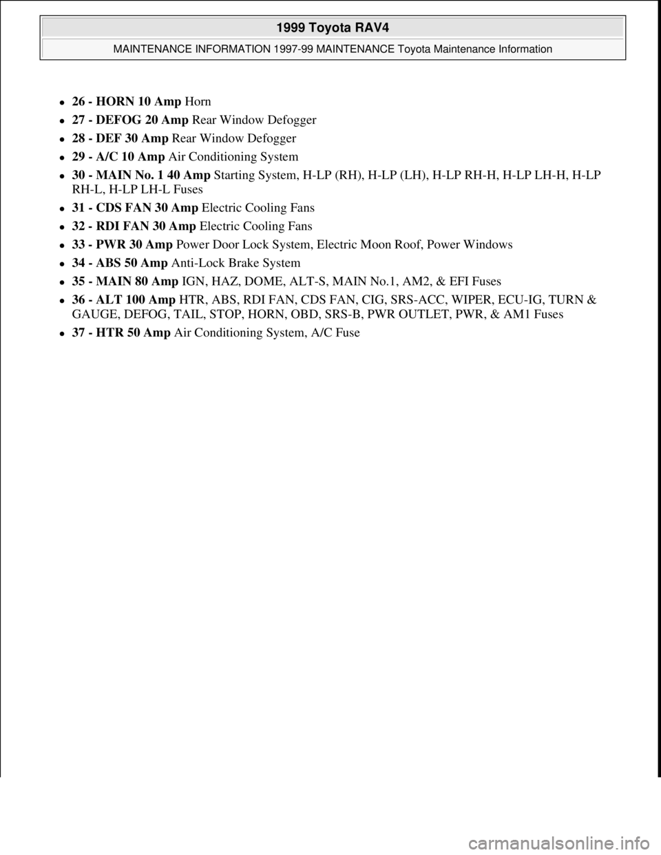
26 - HORN 10 Amp Horn
27 - DEFOG 20 Amp Rear Window Defogger
28 - DEF 30 Amp Rear Window Defogger
29 - A/C 10 Amp Air Conditioning System
30 - MAIN No. 1 40 Amp Starting System, H-LP (RH), H-LP (LH), H-LP RH-H, H-LP LH-H, H-LP
RH-L, H-LP LH-L Fuses
31 - CDS FAN 30 Amp Electric Cooling Fans
32 - RDI FAN 30 Amp Electric Cooling Fans
33 - PWR 30 Amp Power Door Lock System, Electric Moon Roof, Power Windows
34 - ABS 50 Amp Anti-Lock Brake System
35 - MAIN 80 Amp IGN, HAZ, DOME, ALT-S, MAIN No.1, AM2, & EFI Fuses
36 - ALT 100 Amp HTR, ABS, RDI FAN, CDS FAN, CIG, SRS-ACC, WIPER, ECU-IG, TURN &
GAUGE, DEFOG, TAIL, STOP, HORN, OBD, SRS-B, PWR OUTLET, PWR, & AM1 Fuses
37 - HTR 50 Amp Air Conditioning System, A/C Fuse
1999 Toyota RAV4
MAINTENANCE INFORMATION 1997-99 MAINTENANCE Toyota Maintenance Information
Microsoft
Sunday, November 22, 2009 10:32:42 AMPage 28 © 2005 Mitchell Repair Information Company, LLC.
Page 1143 of 1632
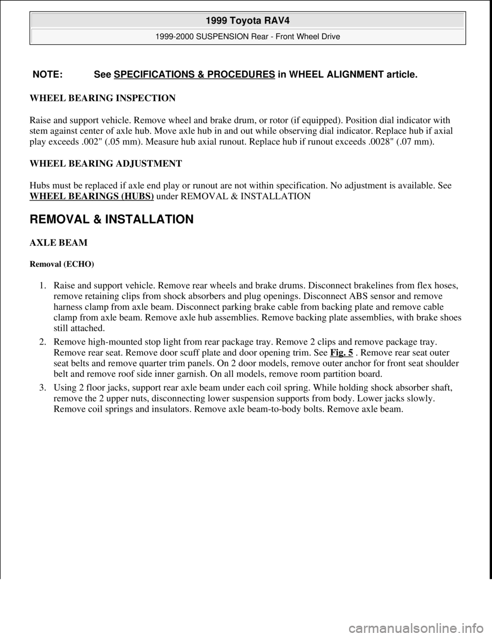
WHEEL BEARING INSPECTION
Raise and support vehicle. Remove wheel and brake drum, or rotor (if equipped). Position dial indicator with
stem against center of axle hub. Move axle hub in and out while observing dial indicator. Replace hub if axial
play exceeds .002" (.05 mm). Measure hub axial runout. Replace hub if runout exceeds .0028" (.07 mm).
WHEEL BEARING ADJUSTMENT
Hubs must be replaced if axle end play or runout are not within specification. No adjustment is available. See
WHEEL BEARINGS (HUBS)
under REMOVAL & INSTALLATION
REMOVAL & INSTALLATION
AXLE BEAM
Removal (ECHO)
1. Raise and support vehicle. Remove rear wheels and brake drums. Disconnect brakelines from flex hoses,
remove retaining clips from shock absorbers and plug openings. Disconnect ABS sensor and remove
harness clamp from axle beam. Disconnect parking brake cable from backing plate and remove cable
clamp from axle beam. Remove axle hub assemblies. Remove backing plate assemblies, with brake shoes
still attached.
2. Remove high-mounted stop light from rear package tray. Remove 2 clips and remove package tray.
Remove rear seat. Remove door scuff plate and door opening trim. See Fig. 5
. Remove rear seat outer
seat belts and remove quarter trim panels. On 2 door models, remove outer anchor for front seat shoulder
belt and remove roof side inner garnish. On all models, remove room partition board.
3. Using 2 floor jacks, support rear axle beam under each coil spring. While holding shock absorber shaft,
remove the 2 upper nuts, disconnecting lower suspension supports from body. Lower jacks slowly.
Remove coil springs and insulators. Remove axle beam-to-
body bolts. Remove axle beam. NOTE: See SPECIFICATIONS & PROCEDURES
in WHEEL ALIGNMENT article.
1999 Toyota RAV4
1999-2000 SUSPENSION Rear - Front Wheel Drive
Microsoft
Sunday, November 22, 2009 10:37:21 AMPage 5 © 2005 Mitchell Repair Information Company, LLC.
Page 1149 of 1632
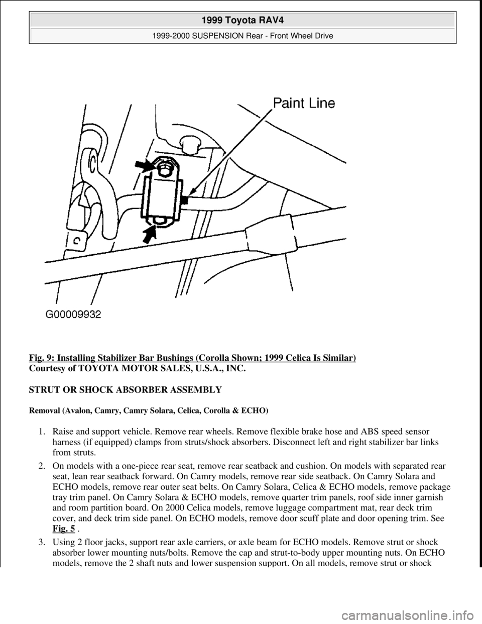
Fig. 9: Installing Stabilizer Bar Bushings (Corolla Shown; 1999 Celica Is Similar)
Courtesy of TOYOTA MOTOR SALES, U.S.A., INC.
STRUT OR SHOCK ABSORBER ASSEMBLY
Removal (Avalon, Camry, Camry Solara, Celica, Corolla & ECHO)
1. Raise and support vehicle. Remove rear wheels. Remove flexible brake hose and ABS speed sensor
harness (if equipped) clamps from struts/shock absorbers. Disconnect left and right stabilizer bar links
from struts.
2. On models with a one-piece rear seat, remove rear seatback and cushion. On models with separated rear
seat, lean rear seatback forward. On Camry models, remove rear side seatback. On Camry Solara and
ECHO models, remove rear outer seat belts. On Camry Solara, Celica & ECHO models, remove package
tray trim panel. On Camry Solara & ECHO models, remove quarter trim panels, roof side inner garnish
and room partition board. On 2000 Celica models, remove luggage compartment mat, rear deck trim
cover, and deck trim side panel. On ECHO models, remove door scuff plate and door opening trim. See
Fig. 5
.
3. Using 2 floor jacks, support rear axle carriers, or axle beam for ECHO models. Remove strut or shock
absorber lower mounting nuts/bolts. Remove the cap and strut-to-body upper mounting nuts. On ECHO
models, remove the 2 shaft nuts and lower suspension support. On all models, remove strut or shock
1999 Toyota RAV4
1999-2000 SUSPENSION Rear - Front Wheel Drive
Microsoft
Sunday, November 22, 2009 10:37:21 AMPage 11 © 2005 Mitchell Repair Information Company, LLC.
Page 1281 of 1632
1999-2000 ACCESSORIES & EQUIPMENT
Power Sun Roofs
DESCRIPTION & OPERATION
AVALON (1999) & CELICA (1999)
The power sun roof system has a tilt and sliding mode. Ignition switch must be in ON position for sun roof to
operate. If all doors are closed, sun roof will operate for an additional 60 seconds after ignition is turned off.
Power sun roof is opened and closed by pressing and holding the open or close button. As a safety precaution
feature, when sliding sun roof closed, sun roof will stop part way until sun roof switch is released and pressed a
second time. Sun shade will either open with sun roof operation or when manually operated.
AVALON (2000) & LAND CRUISER (2000)
The power sun roof system has a tilt and sliding mode. Ignition switch must be in ON position for sun roof to
operate. If all doors are closed, sun roof will operate for an additional 43-45 seconds after ignition is turned off.
Power sun roof slide operation is equipped with an one-touch open and close feature. Press either button to stop
sun roof operation. The tilt operation is not equipped with the one-touch feature. To reduce wind throbs while
driving, power sun roof will stop 0.4" (10 mm) on Avalon and 1.4" (35 mm) on Land Cruiser from its fully
opened position. To completely open sun roof, press sun roof switch a second time.
As a safety precaution feature, the power sun roof system is equipped with a jam protection function. During
closing operation, the sun roof will stop and open half way if something is caught between sun roof and frame.
If sun roof is damaged, received a strong enough impact or sat upon, the jam protection function may work even
when nothing is caught between the sun roof and the frame. Sun shade will either open with sun roof operation
or when manually operated.
CAMRY
The power sun roof system has a tilt mode and a sliding mode. Ignition switch must be in ON position for sun
roof to operate. If all doors are closed, sun roof will operate for an additional 45 seconds after ignition is turned
off. Power sun roof is equipped with a one-touch open and close feature. Press either button to stop sun roof
operation. The tilt operation is not equipped with the one-touch feature. As a safety precaution feature, when
sliding sun roof closed, sun roof will stop part way until sun roof switch is released and pressed a second time.
Sun shade will either open with sun roof operation or when manually operated.
CAMRY SOLARA & LAND CRUISER (1999) NOTE: This article also applies to Lexus LX470. Refer to Land Cruiser, unless
otherwise indicated.
NOTE: The Camry may have been manufactured by Toyota Motor Mfg. U.S.A. (USA
built), or manufactured by Toyota Motor Corp. Japan (Japan built). Ensure
correct procedures are used when servicing vehicle.
1999 Toyota RAV4
1999-2000 ACCESSORIES & EQUIPMENT Power Sun Roofs
1999 Toyota RAV4
1999-2000 ACCESSORIES & EQUIPMENT Power Sun Roofs
Microsoft
Sunday, November 22, 2009 10:58:29 AMPage 1 © 2005 Mitchell Repair Information Company, LLC.
Microsoft
Sunday, November 22, 2009 10:58:34 AMPage 1 © 2005 Mitchell Repair Information Company, LLC.