cruise control TOYOTA RAV4 1996 Service Manual Online
[x] Cancel search | Manufacturer: TOYOTA, Model Year: 1996, Model line: RAV4, Model: TOYOTA RAV4 1996Pages: 1632, PDF Size: 41.64 MB
Page 1314 of 1632
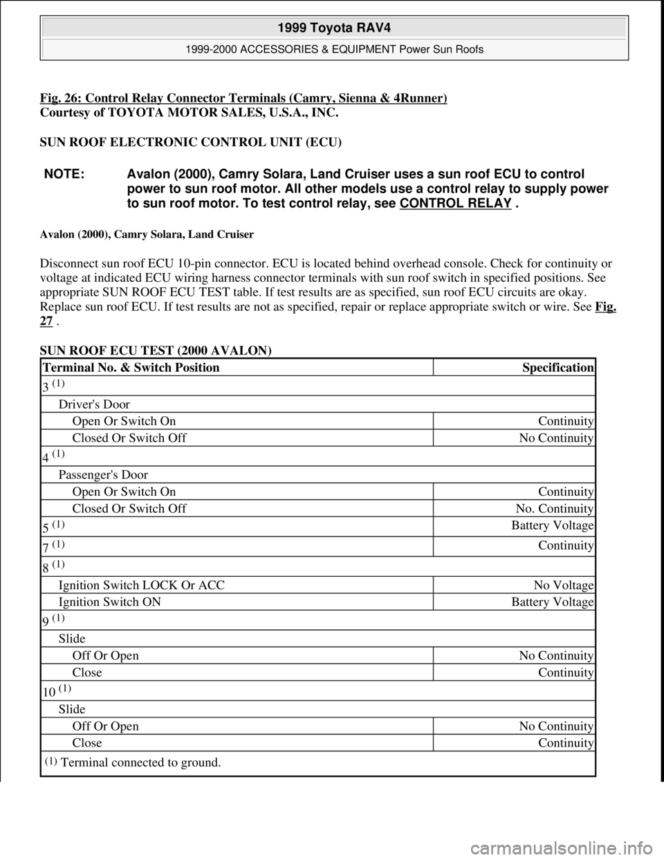
Fig. 26: Control Relay Connector Terminals (Camry, Sienna & 4Runner)
Courtesy of TOYOTA MOTOR SALES, U.S.A., INC.
SUN ROOF ELECTRONIC CONTROL UNIT (ECU)
Avalon (2000), Camry Solara, Land Cruiser
Disconnect sun roof ECU 10-pin connector. ECU is located behind overhead console. Check for continuity or
voltage at indicated ECU wiring harness connector terminals with sun roof switch in specified positions. See
appropriate SUN ROOF ECU TEST table. If test results are as specified, sun roof ECU circuits are okay.
Replace sun roof ECU. If test results are not as specified, repair or replace appropriate switch or wire. See Fig.
27 .
SUN ROOF ECU TEST (2000 AVALON) NOTE: Avalon (2000), Camry Solara, Land Cruiser uses a sun roof ECU to control
power to sun roof motor. All other models use a control relay to supply power
to sun roof motor. To test control relay, see CONTROL RELAY
.
Terminal No. & Switch PositionSpecification
3 (1)
Driver's Door
Open Or Switch OnContinuity
Closed Or Switch OffNo Continuity
4 (1)
Passenger's Door
Open Or Switch OnContinuity
Closed Or Switch OffNo. Continuity
5 (1) Battery Voltage
7 (1) Continuity
8 (1)
Ignition Switch LOCK Or ACCNo Voltage
Ignition Switch ONBattery Voltage
9 (1)
Slide
Off Or OpenNo Continuity
CloseContinuity
10 (1)
Slide
Off Or OpenNo Continuity
CloseContinuity
(1)Terminal connected to ground.
1999 Toyota RAV4
1999-2000 ACCESSORIES & EQUIPMENT Power Sun Roofs
Microsoft
Sunday, November 22, 2009 10:58:30 AMPage 34 © 2005 Mitchell Repair Information Company, LLC.
Page 1316 of 1632
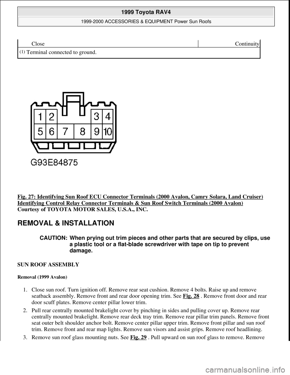
Fig. 27: Identifying Sun Roof ECU Connector Terminals (2000 Avalon, Camry Solara, Land Cruiser)
Identifying Control Relay Connector Terminals & Sun Roof Switch Terminals (2000 Avalon)
Courtesy of TOYOTA MOTOR SALES, U.S.A., INC.
REMOVAL & INSTALLATION
SUN ROOF ASSEMBLY
Removal (1999 Avalon)
1. Close sun roof. Turn ignition off. Remove rear seat cushion. Remove 4 bolts. Raise up and remove
seatback assembly. Remove front and rear door opening trim. See Fig. 28
. Remove front door and rear
door scuff plates. Remove center pillar lower trim.
2. Pull rear centrally mounted brakelight cover by pinching in sides and pulling cover up. Remove rear
centrally mounted brakelight. Remove rear deck tray trim. Remove rear pillar trim panels. Remove front
seat outer belt shoulder anchor bolt. Remove center pillar upper trim. Remove front pillar and sun roof
trim. Remove front and rear map lights. Remove sun visors and assist grips. Remove roof headlining.
3. Remove sun roof
glass mounting nuts. See Fig. 29. Pull upward on sun roof glass to remove. Remove
CloseContinuity
(1)Terminal connected to ground.
CAUTION: When prying out trim pieces and other parts that are secured by clips, use
a plastic tool or a flat-blade screwdriver with tape on tip to prevent
damage.
1999 Toyota RAV4
1999-2000 ACCESSORIES & EQUIPMENT Power Sun Roofs
Microsoft
Sunday, November 22, 2009 10:58:30 AMPage 36 © 2005 Mitchell Repair Information Company, LLC.
Page 1453 of 1632
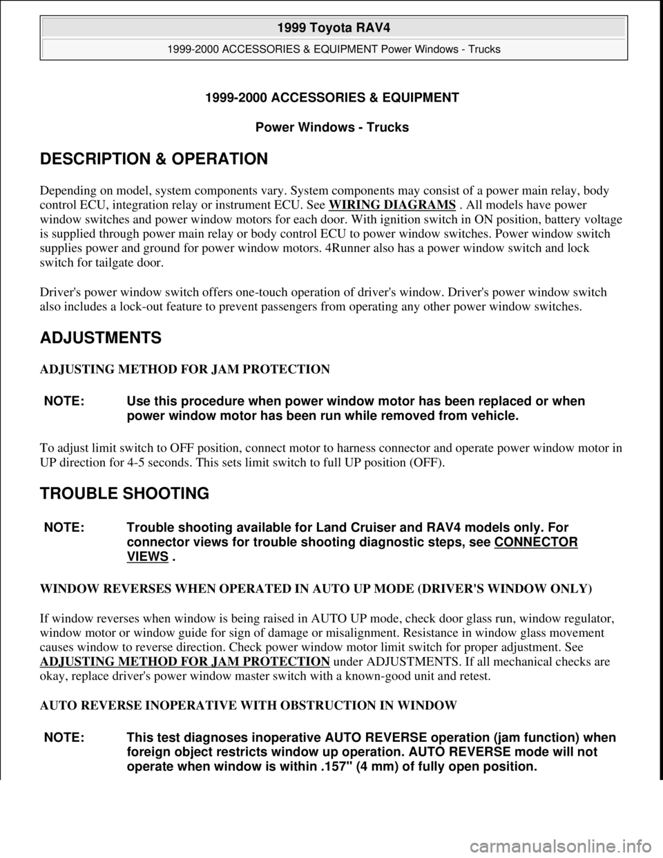
1999-2000 ACCESSORIES & EQUIPMENT
Power Windows - Trucks
DESCRIPTION & OPERATION
Depending on model, system components vary. System components may consist of a power main relay, body
control ECU, integration relay or instrument ECU. See WIRING DIAGRAMS
. All models have power
window switches and power window motors for each door. With ignition switch in ON position, battery voltage
is supplied through power main relay or body control ECU to power window switches. Power window switch
supplies power and ground for power window motors. 4Runner also has a power window switch and lock
switch for tailgate door.
Driver's power window switch offers one-touch operation of driver's window. Driver's power window switch
also includes a lock-out feature to prevent passengers from operating any other power window switches.
ADJUSTMENTS
ADJUSTING METHOD FOR JAM PROTECTION
To adjust limit switch to OFF position, connect motor to harness connector and operate power window motor in
UP direction for 4-5 seconds. This sets limit switch to full UP position (OFF).
TROUBLE SHOOTING
WINDOW REVERSES WHEN OPERATED IN AUTO UP MODE (DRIVER'S WINDOW ONLY)
If window reverses when window is being raised in AUTO UP mode, check door glass run, window regulator,
window motor or window guide for sign of damage or misalignment. Resistance in window glass movement
causes window to reverse direction. Check power window motor limit switch for proper adjustment. See
ADJUSTING METHOD FOR JAM PROTECTION
under ADJUSTMENTS. If all mechanical checks are
okay, replace driver's power window master switch with a known-good unit and retest.
AUTO REVERSE INOPERATIVE WITH OBSTRUCTION IN WINDOW NOTE: Use this procedure when power window motor has been replaced or when
power window motor has been run while removed from vehicle.
NOTE: Trouble shooting available for Land Cruiser and RAV4 models only. For
connector views for trouble shooting diagnostic steps, see CONNECTOR
VIEWS .
NOTE: This test diagnoses inoperative AUTO REVERSE operation (jam function) when
foreign object restricts window up operation. AUTO REVERSE mode will not
operate when window is within .157" (4 mm) of fully open position.
1999 Toyota RAV4
1999-2000 ACCESSORIES & EQUIPMENT Power Windows - Trucks
1999 Toyota RAV4
1999-2000 ACCESSORIES & EQUIPMENT Power Windows - Trucks
Microsoft
Sunday, November 22, 2009 10:59:35 AMPage 1 © 2005 Mitchell Repair Information Company, LLC.
Microsoft
Sunday, November 22, 2009 10:59:39 AMPage 1 © 2005 Mitchell Repair Information Company, LLC.
Page 1454 of 1632
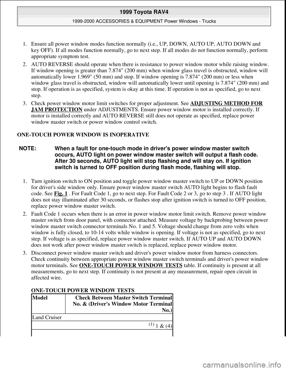
1. Ensure all power window modes function normally (i.e., UP, DOWN, AUTO UP, AUTO DOWN and
key OFF). If all modes function normally, go to next step. If all modes do not function normally, perform
appropriate symptom test.
2. AUTO REVERSE should operate when there is resistance to power window motor while raising window.
If window opening is greater than 7.874" (200 mm) when window glass travel is obstructed, window will
automatically lower 1.969" (50 mm) and stop. If window opening is 7.874" (200 mm) or less when
window glass travel is obstructed, window will automatically lower until opening is 7.874" (200 mm) and
stop. If operation is as specified, system is okay at this time. If operation is not as specified, go to next
step.
3. Check power window motor limit switches for proper adjustment. See ADJUSTING METHOD FOR
JAM PROTECTION under ADJUSTMENTS. Ensure power window motor is installed correctly. If
motor is installed correctly and AUTO REVERSE still does not operate as specified, replace power
window master switch or power window control switch.
ONE-TOUCH POWER WINDOW IS INOPERATIVE
1. Turn ignition switch to ON position and toggle power window master switch to UP or DOWN position
for driver's side window only. Ensure power window master switch AUTO light begins to flash fault
code. See Fig. 1
. For Fault Code 1, go to next step. For Fault Code 2 or 3, go to step 3 . If AUTO light
does not stay illuminated after 30 seconds, or flashes stop after ignition switch is turned to OFF position,
replace power window master switch.
2. Fault Code 1 occurs when there is an error in power window motor limit switch. Remove power window
master switch from door panel, with connector attached. Measure voltage by backprobing between power
window master switch connector terminals No. 1 and 5. Voltage should change from zero volts when
window is fully closed, to 10-14 volts while window is opening. If voltage is not as specified, go to next
step. If voltage is as specified, replace power window master switch. If AUTO UP and AUTO DOWN
does not work after power window master switch is replaced, replace power window motor.
3. Disconnect power window master switch and driver's power window motor from harness connectors.
Check continuity between appropriate power window master switch terminals and driver's power window
motor terminals. See ONE
-TOUCH POWER WINDOW TESTS table. If continuity is present at all
measurements, go to next step. If continuity is not present at any measurement, repair open circuit in
affected wire.
ONE-TOUCH POWER WINDOW TESTS NOTE: When a fault for one-touch mode in driver's power window master switch
occurs, AUTO light on power window master switch will output a flash code.
After 30 seconds, AUTO light will stop flashing and will stay on. If ignition
switch is turned to OFF position during flash mode, flashing will stop.
ModelCheck Between Master Switch Terminal
No. & (Driver's Window Motor Terminal
No.)
Land Cruiser
(1) 1 & (4)
1999 Toyota RAV4
1999-2000 ACCESSORIES & EQUIPMENT Power Windows - Trucks
Microsoft
Sunday, November 22, 2009 10:59:35 AMPage 2 © 2005 Mitchell Repair Information Company, LLC.
Page 1512 of 1632
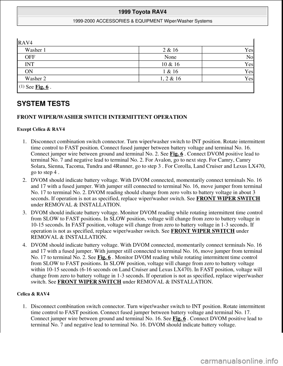
SYSTEM TESTS
FRONT WIPER/WASHER SWITCH INTERMITTENT OPERATION
Except Celica & RAV4
1. Disconnect combination switch connector. Turn wiper/washer switch to INT position. Rotate intermittent
time control to FAST position. Connect fused jumper between battery voltage and terminal No. 16.
Connect jumper wire between ground and terminal No. 2. See Fig. 6
. Connect DVOM positive lead to
terminal No. 7 and negative lead to terminal No. 2. For Avalon, go to next step. For Camry, Camry
Solara, Sienna, Tacoma, Tundra and 4Runner, go to step 3 . For Corolla, Land Cruiser and Lexus LX470,
go to step 4 .
2. DVOM should indicate battery voltage. With DVOM connected, momentarily connect terminals No. 16
and 17 with a fused jumper. With jumper still connected to terminal No. 16, move jumper from terminal
No. 17 to terminal No. 2. DVOM reading should change from zero volts to battery voltage in about 3
seconds. If operation is not as specified, replace wiper/washer switch. See FRONT WIPER SWITCH
under REMOVAL & INSTALLATION.
3. DVOM should indicate battery voltage. Monitor DVOM reading while rotating intermittent time control
from SLOW to FAST positions. In SLOW position, voltage will change from zero to battery voltage in
10-15 seconds. In FAST position, voltage will change from zero to battery voltage in 1-3 seconds. If
operation is not as specified, replace wiper/washer switch. See FRONT WIPER SWITCH
under
REMOVAL & INSTALLATION.
4. DVOM should indicate battery voltage. With DVOM connected, momentarily connect terminals No. 16
and 17 with a fused jumper. With jumper still connected to terminal No. 16, move jumper from terminal
No. 17 to terminal No. 2. See Fig. 6
. Monitor DVOM reading while rotating intermittent time control
from SLOW to FAST positions. In SLOW position, voltage will change from zero to battery voltage
within 10-15 seconds (6-16 seconds on Land Cruiser and Lexus LX470). In FAST position, voltage will
change from zero to battery voltage in 1-3 seconds. If operation is not as specified, replace wiper/washer
switch. See FRONT WIPER SWITCH
under REMOVAL & INSTALLATION.
Celica & RAV4
1. Disconnect combination switch connector. Turn wiper/washer switch to INT position. Rotate intermittent
time control to FAST position. Connect fused jumper between battery voltage and terminal No. 17.
Connect jumper wire between ground and terminal No. 16. See Fig. 6
. Connect DVOM positive lead to
terminal No. 7 and ne
gative lead to terminal No. 16. DVOM should indicate battery voltage.
RAV4
Washer 12 & 16Yes
OFFNoneNo
INT10 & 16Yes
ON1 & 16Yes
Washer 21, 2 & 16Yes
(1)See Fig. 6 .
1999 Toyota RAV4
1999-2000 ACCESSORIES & EQUIPMENT Wiper/Washer Systems
Microsoft
Sunday, November 22, 2009 11:01:20 AMPage 17 © 2005 Mitchell Repair Information Company, LLC.
Page 1568 of 1632

Fig. 5: Cooling Fan Circuit
CRUISE CONTROL
1999 Toyota RAV4
1999 System Wiring Diagrams Toyota - RAV4
Microsoft
Sunday, November 22, 2009 10:50:58 AMPage 11 © 2005 Mitchell Repair Information Company, LLC.
Page 1570 of 1632

Fig. 6: Cruise Control Circuit
DEFOGGERS
1999 Toyota RAV4
1999 System Wiring Diagrams Toyota - RAV4
Microsoft
Sunday, November 22, 2009 10:50:58 AMPage 13 © 2005 Mitchell Repair Information Company, LLC.