cruise control TOYOTA RAV4 1996 Service Workshop Manual
[x] Cancel search | Manufacturer: TOYOTA, Model Year: 1996, Model line: RAV4, Model: TOYOTA RAV4 1996Pages: 1632, PDF Size: 41.64 MB
Page 627 of 1632
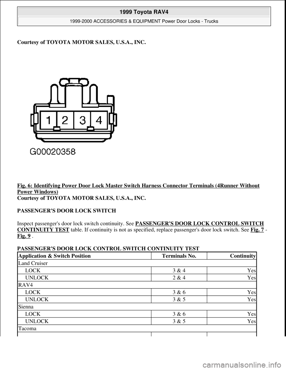
Courtesy of TOYOTA MOTOR SALES, U.S.A., INC.
Fig. 6: Identifying Power Door Lock Master Switch Harness Connector Terminals (4Runner Without
Power Windows)
Courtesy of TOYOTA MOTOR SALES, U.S.A., INC.
PASSENGER'S DOOR LOCK SWITCH
Inspect passenger's door lock switch continuity. See PASSENGER'S DOOR LOCK CONTROL SWITCH
CONTINUITY TEST table. If continuity is not as specified, replace passenger's door lock switch. See Fig. 7 -
Fig. 9
.
PASSENGER'S DOOR LOCK CONTROL SWITCH CONTINUITY TEST
Application & Switch PositionTerminals No.Continuity
Land Cruiser
LOCK3 & 4Yes
UNLOCK2 & 4Yes
RAV4
LOCK3 & 6Yes
UNLOCK3 & 5Yes
Sienna
LOCK3 & 6Yes
UNLOCK3 & 5Yes
Tacoma
1999 Toyota RAV4
1999-2000 ACCESSORIES & EQUIPMENT Power Door Locks - Trucks
Microsoft
Sunday, November 22, 2009 10:53:11 AMPage 6 © 2005 Mitchell Repair Information Company, LLC.
Page 644 of 1632
Land Cruiser
1. Connect negative lead from battery to door lock actuator terminal No. 2. Connect positive lead from
ammeter to door lock actuator terminal No. 3 and negative ammeter lead to positive battery terminal. See
Fig. 16
. Current should change from 3.2 amps to less than 0.5 amps within 20-70 seconds.
2. Wait approximately 60 seconds and connect positive lead from battery to terminal No. 2 and negative
lead to terminal No. 3. Door lock actuator should move to LOCK position. If operation is not as specified,
replace door lock actuator assembly.
REMOVAL & INSTALLATION
POWER DOOR LOCK ACTUATORS (FRONT DOORS)
Removal & Installation (Land Cruiser)
1. Remove panel covering 3 screws for outside rear view mirror on inside of door by prying out with a
screwdriver. Remove interior window control switch by prying up on front of plastic switch retaining
plate. See Fig. 24
and Fig. 25 . Remove inside door handle bezel plug, screw and pry out bezel. See Fig.
26 . Remove side door panel courtesy light and wiring harness connector. Remove 7 interior door panel
screws, 3 clips and 2 caps.
2. Remove one screw, 2 cables and interior door handle. Remove speaker. Remove outside rear view mirror
assembly by removing 3 bolts. Remove service hole cover. Remove door molding at top of door, where
window slides. See Fig. 27
. Remove 2 bolts and remove door glass. Remove second speaker. Remove
lower glass track and frame. Remove window regulator 5 bolts and electrical connector through service
hole.
3. Remove door lock wiring harness connector. Disconnect 2 links which connect to outside door handle.
Remove 3 Torx (T-30) screws and remove door lock actuator through service hole.
4. To install, reverse removal procedure. See TORQUE SPECIFICATIONS
. NOTE: Tape end of screwdriver when using it as a pry tool.
1999 Toyota RAV4
1999-2000 ACCESSORIES & EQUIPMENT Power Door Locks - Trucks
Microsoft
Sunday, November 22, 2009 10:53:11 AMPage 23 © 2005 Mitchell Repair Information Company, LLC.
Page 650 of 1632
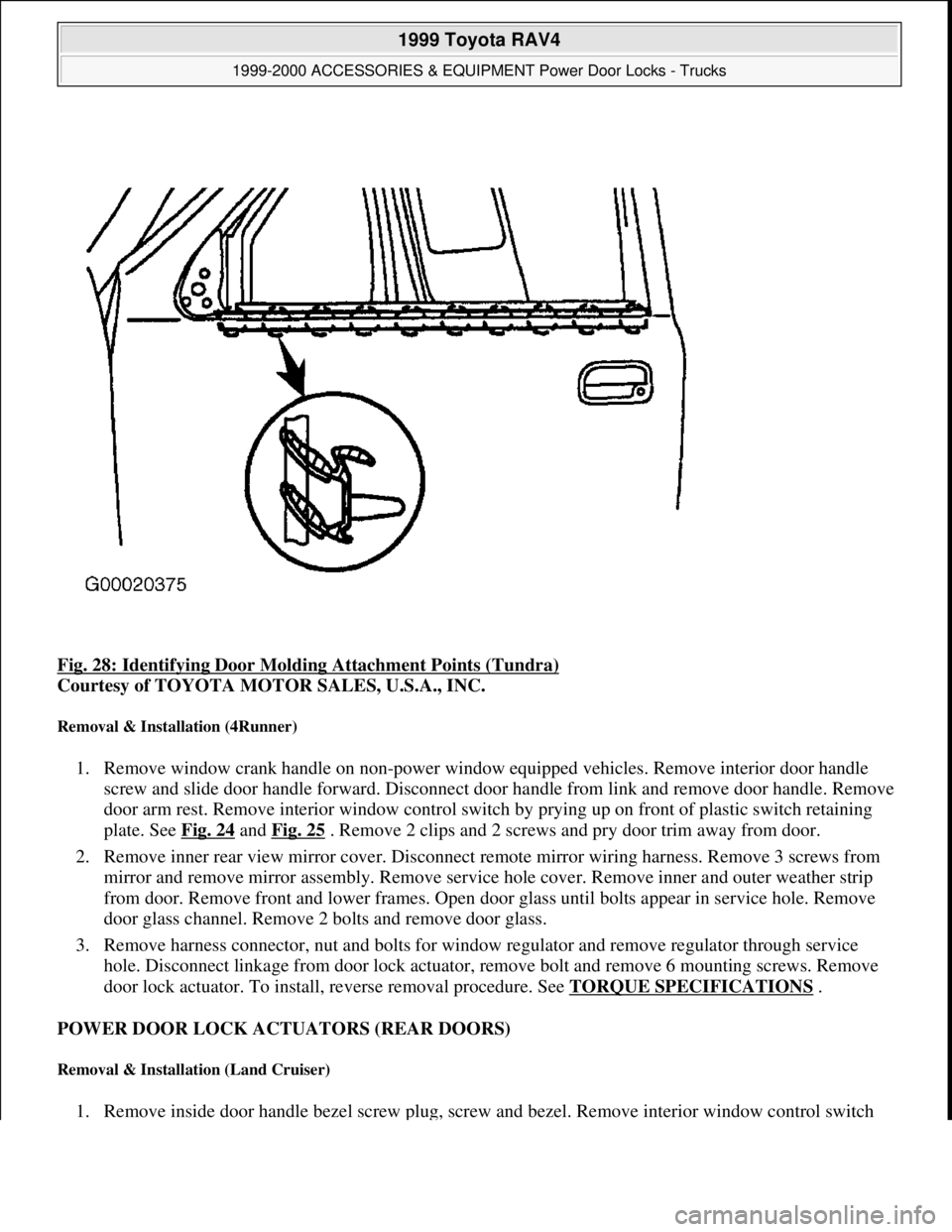
Fig. 28: Identifying Door Molding Attachment Points (Tundra)
Courtesy of TOYOTA MOTOR SALES, U.S.A., INC.
Removal & Installation (4Runner)
1. Remove window crank handle on non-power window equipped vehicles. Remove interior door handle
screw and slide door handle forward. Disconnect door handle from link and remove door handle. Remove
door arm rest. Remove interior window control switch by prying up on front of plastic switch retaining
plate. See Fig. 24
and Fig. 25 . Remove 2 clips and 2 screws and pry door trim away from door.
2. Remove inner rear view mirror cover. Disconnect remote mirror wiring harness. Remove 3 screws from
mirror and remove mirror assembly. Remove service hole cover. Remove inner and outer weather strip
from door. Remove front and lower frames. Open door glass until bolts appear in service hole. Remove
door glass channel. Remove 2 bolts and remove door glass.
3. Remove harness connector, nut and bolts for window regulator and remove regulator through service
hole. Disconnect linkage from door lock actuator, remove bolt and remove 6 mounting screws. Remove
door lock actuator. To install, reverse removal procedure. See TORQUE SPECIFICATIONS
.
POWER DOOR LOCK ACTUATORS (REAR DOORS)
Removal & Installation (Land Cruiser)
1. Remove inside door handle bezel screw plug, screw and bezel. Remove interior window control switch
1999 Toyota RAV4
1999-2000 ACCESSORIES & EQUIPMENT Power Door Locks - Trucks
Microsoft
Sunday, November 22, 2009 10:53:11 AMPage 29 © 2005 Mitchell Repair Information Company, LLC.
Page 651 of 1632
by prying up on front of plastic switch retaining plate and disconnect electrical harness connector. See
Fig. 24
and Fig. 25 . Remove door courtesy light and harness connector. Remove 3 screws and 4 clips.
Pry out to remove door panel.
2. Remove interior door handle screw and 2 cables. Remove door handle assembly. Remove service hole
cover and move door handle control cables and wiring harness through hole. Remove door molding at top
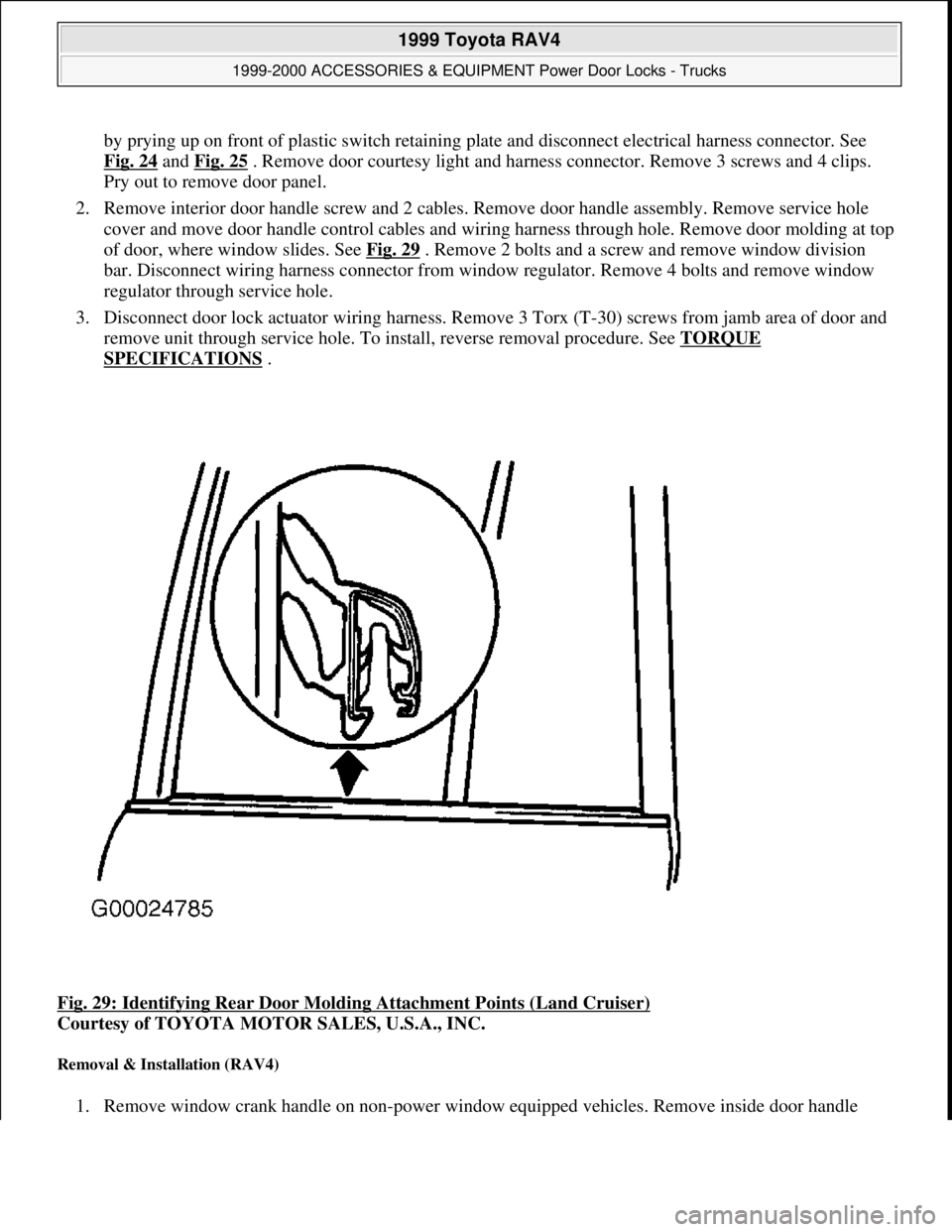
of door, where window slides. See Fig. 29
. Remove 2 bolts and a screw and remove window division
bar. Disconnect wiring harness connector from window regulator. Remove 4 bolts and remove window
regulator through service hole.
3. Disconnect door lock actuator wiring harness. Remove 3 Torx (T-30) screws from jamb area of door and
remove unit through service hole. To install, reverse removal procedure. See TORQUE
SPECIFICATIONS .
Fig. 29: Identifying Rear Door Molding Attachment Points (Land Cruiser)
Courtesy of TOYOTA MOTOR SALES, U.S.A., INC.
Removal & Installation (RAV4)
1. Remove window crank handle on non-power window equipped vehicles. Remove inside door handle
1999 Toyota RAV4
1999-2000 ACCESSORIES & EQUIPMENT Power Door Locks - Trucks
Microsoft
Sunday, November 22, 2009 10:53:11 AMPage 30 © 2005 Mitchell Repair Information Company, LLC.
Page 652 of 1632
bezel. Remove 2 screws from inside door pull. Pry interior door panel loose from door. Remove power
window switch if equipped.
2. Remove 2 screws, linkage rod and inside door handle assembly. Remove service hole cover. Remove
door molding at top of door, where window slides. Remove window track. Remove division bar. Remove
rear door quarter window and glass.
3. Remove electrical connector from window regulator (if equipped) and remove window regulator through
service hole. Remove door lock actuator linkage, 3 screws and remove door lock actuator through service
hole. To install reverse removal procedure. See TORQUE SPECIFICATIONS
.
Removal & Installation (Tundra)
1. Remove one screw and inside door handle bezel. Remove one screw and remove armrest. Pry door trim
away from door. Remove 4 screws and remove speaker. Remove inside door handle screw and slide door
handle forward and disconnect cable.
2. Remove service hole cover. Remove access door controller cables, links and clamps. Remove 3 access
door controller bolts and access door controller. Disconnect lower door lock harness connector. Remove 3
Torx screws (T-30) and remove lower door lock assembly.
3. To install reverse removal procedure. See TORQUE SPECIFICATIONS
.
Removal & Installation (4Runner)
1. Remove window crank handle on non-power window equipped vehicles. Remove interior door handle
screw and slide door handle forward. Disconnect door handle from link and remove door handle. Remove
door arm rest. Remove interior window control switch by prying up on front of plastic switch retaining
plate. Remove 2 clips and 2 screws and pry door trim away from door.
2. Remove service hole cover. Remove inner and outer weather strip from door. Remove division bar.
Remove quarter window glass with weatherstrip and glass channel. Disconnect harness connector.
Remove clip and pull down on locking knob. Disconnect linkage from door handle. Remove 3 door lock
mounting screws and remove door lock actuator assembly.
3. To install reverse removal procedure. See TORQUE SPECIFICATIONS
.
POWER DOOR LOCK ACTUATORS (LIFTGATE & BACK DOOR)
Removal & Installation (Land Cruiser)
1. Remove assist grip. Remove inside handle bezel. Remove back door garnish around rear window.
Remove rear wiper arm and grommet. Remove 2 bolts from rear wiper linkage assembly and remove 3
bolts from rear wiper motor assembly. Remove lower back door weather stripping. Remove 2 inside back
door handle mounting bolts and remove inside back door handle linkage rod and remove back door inside
handle.
2. Remove linkage and 3 mounting bolts from back door controller and lock actuator assembly. Remove
back door linkage and lock actuator assembly. To install, reverse removal procedure. See TORQUE
SPECIFICATIONS .
Removal & Installation (RAV4)
1999 Toyota RAV4
1999-2000 ACCESSORIES & EQUIPMENT Power Door Locks - Trucks
Microsoft
Sunday, November 22, 2009 10:53:11 AMPage 31 © 2005 Mitchell Repair Information Company, LLC.
Page 675 of 1632
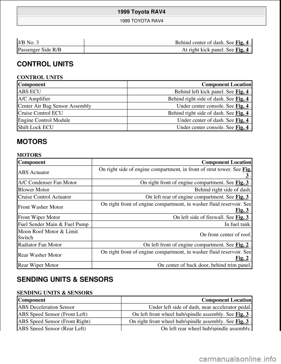
CONTROL UNITS
CONTROL UNITS
MOTORS
MOTORS
SENDING UNITS & SENSORS
SENDING UNITS & SENSORS
J/B No. 3Behind center of dash. See Fig. 4 .
Passenger Side R/BAt right kick panel. See Fig. 4 .
ComponentComponent Location
ABS ECUBehind left kick panel. See Fig. 4 .
A/C AmplifierBehind right side of dash. See Fig. 4 .
Center Air Bag Sensor AssemblyUnder center console. See Fig. 4 .
Cruise Control ECUBehind right side of dash. See Fig. 4 .
Engine Control ModuleUnder center of dash. See Fig. 4 .
Shift Lock ECUUnder center console. See Fig. 4 .
ComponentComponent Location
ABS ActuatorOn right side of engine compartment, in front of strut tower. See Fig.
3 .
A/C Condenser Fan MotorOn right front of engine compartment. See Fig. 3 .
Blower MotorBehind right side of dash.
Cruise Control ActuatorOn left rear of engine compartment. See Fig. 3 .
Front Washer MotorOn right front of engine compartment, in washer fluid reservoir. See
Fig. 3
.
Front Wiper MotorOn left side of firewall. See Fig. 3 .
Fuel Sender Main & Fuel PumpIn fuel tank.
Moon Roof Motor & Limit
SwitchOn front center of roof.
Radiator Fan MotorOn left front of engine compartment. See Fig. 2 .
Rear Washer MotorOn right front of engine compartment, in washer fluid reservoir. See
Fig. 2
.
Rear Wiper MotorOn center of back door, behind trim panel.
ComponentComponent Location
ABS Deceleration SensorUnder left side of dash, near accelerator pedal.
ABS Speed Sensor (Front Left)On left front wheel hub/spindle assembly. See Fig. 3 .
ABS Speed Sensor (Front Right)On right front wheel hub/spindle assembly. See Fig. 3 .
ABS Speed Sensor (Rear Left)On left rear wheel hub/spindle assembly.
1999 Toyota RAV4
1999 TOYOTA RAV4
Microsoft
Sunday, November 22, 2009 10:17:32 AMPage 2 © 2005 Mitchell Repair Information Company, LLC.
Page 677 of 1632
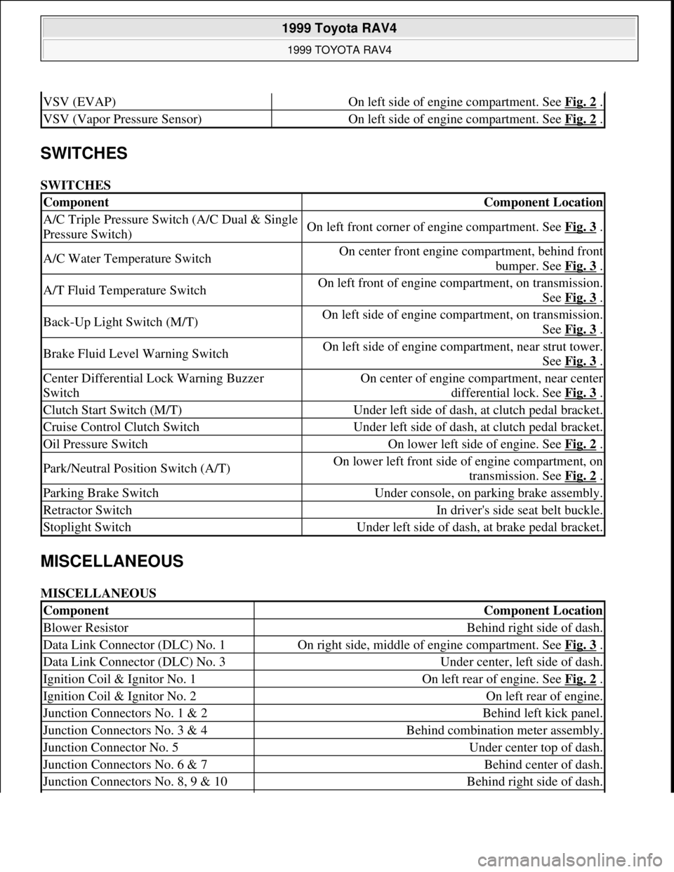
SWITCHES
SWITCHES
MISCELLANEOUS
MISCELLANEOUS
VSV (EVAP)On left side of engine compartment. See Fig. 2 .
VSV (Vapor Pressure Sensor)On left side of engine compartment. See Fig. 2 .
ComponentComponent Location
A/C Triple Pressure Switch (A/C Dual & Single
Pressure Switch)On left front corner of engine compartment. See Fig. 3 .
A/C Water Temperature SwitchOn center front engine compartment, behind front
bumper. See Fig. 3
.
A/T Fluid Temperature SwitchOn left front of engine compartment, on transmission.
See Fig. 3
.
Back-Up Light Switch (M/T)On left side of engine compartment, on transmission.
See Fig. 3
.
Brake Fluid Level Warning SwitchOn left side of engine compartment, near strut tower.
See Fig. 3
.
Center Differential Lock Warning Buzzer
SwitchOn center of engine compartment, near center
differential lock. See Fig. 3
.
Clutch Start Switch (M/T)Under left side of dash, at clutch pedal bracket.
Cruise Control Clutch SwitchUnder left side of dash, at clutch pedal bracket.
Oil Pressure SwitchOn lower left side of engine. See Fig. 2 .
Park/Neutral Position Switch (A/T)On lower left front side of engine compartment, on
transmission. See Fig. 2
.
Parking Brake SwitchUnder console, on parking brake assembly.
Retractor SwitchIn driver's side seat belt buckle.
Stoplight SwitchUnder left side of dash, at brake pedal bracket.
ComponentComponent Location
Blower ResistorBehind right side of dash.
Data Link Connector (DLC) No. 1On right side, middle of engine compartment. See Fig. 3 .
Data Link Connector (DLC) No. 3Under center, left side of dash.
Ignition Coil & Ignitor No. 1On left rear of engine. See Fig. 2 .
Ignition Coil & Ignitor No. 2On left rear of engine.
Junction Connectors No. 1 & 2Behind left kick panel.
Junction Connectors No. 3 & 4Behind combination meter assembly.
Junction Connector No. 5Under center top of dash.
Junction Connectors No. 6 & 7Behind center of dash.
Junction Connectors No. 8, 9 & 10Behind right side of dash.
1999 Toyota RAV4
1999 TOYOTA RAV4
Microsoft
Sunday, November 22, 2009 10:17:32 AMPage 4 © 2005 Mitchell Repair Information Company, LLC.
Page 891 of 1632
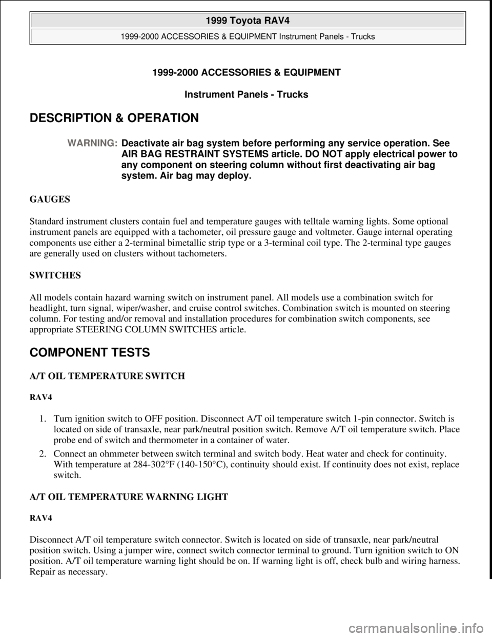
1999-2000 ACCESSORIES & EQUIPMENT
Instrument Panels - Trucks
DESCRIPTION & OPERATION
GAUGES
Standard instrument clusters contain fuel and temperature gauges with telltale warning lights. Some optional
instrument panels are equipped with a tachometer, oil pressure gauge and voltmeter. Gauge internal operating
components use either a 2-terminal bimetallic strip type or a 3-terminal coil type. The 2-terminal type gauges
are generally used on clusters without tachometers.
SWITCHES
All models contain hazard warning switch on instrument panel. All models use a combination switch for
headlight, turn signal, wiper/washer, and cruise control switches. Combination switch is mounted on steering
column. For testing and/or removal and installation procedures for combination switch components, see
appropriate STEERING COLUMN SWITCHES article.
COMPONENT TESTS
A/T OIL TEMPERATURE SWITCH
RAV4
1. Turn ignition switch to OFF position. Disconnect A/T oil temperature switch 1-pin connector. Switch is
located on side of transaxle, near park/neutral position switch. Remove A/T oil temperature switch. Place
probe end of switch and thermometer in a container of water.
2. Connect an ohmmeter between switch terminal and switch body. Heat water and check for continuity.
With temperature at 284-302°F (140-150°C), continuity should exist. If continuity does not exist, replace
switch.
A/T OIL TEMPERATURE WARNING LIGHT
RAV4
Disconnect A/T oil temperature switch connector. Switch is located on side of transaxle, near park/neutral
position switch. Using a jumper wire, connect switch connector terminal to ground. Turn ignition switch to ON
position. A/T oil temperature warning light should be on. If warning light is off, check bulb and wiring harness.
Repair as necessary. WARNING:Deactivate air bag system before performing any service operation. See
AIR BAG RESTRAINT SYSTEMS article. DO NOT apply electrical power to
any component on steering column without first deactivating air bag
system. Air bag may deploy.
1999 Toyota RAV4
1999-2000 ACCESSORIES & EQUIPMENT Instrument Panels - Trucks
1999 Toyota RAV4
1999-2000 ACCESSORIES & EQUIPMENT Instrument Panels - Trucks
Microsoft
Sunday, November 22, 2009 10:54:09 AMPage 1 © 2005 Mitchell Repair Information Company, LLC.
Microsoft
Sunday, November 22, 2009 10:54:14 AMPage 1 © 2005 Mitchell Repair Information Company, LLC.
Page 909 of 1632
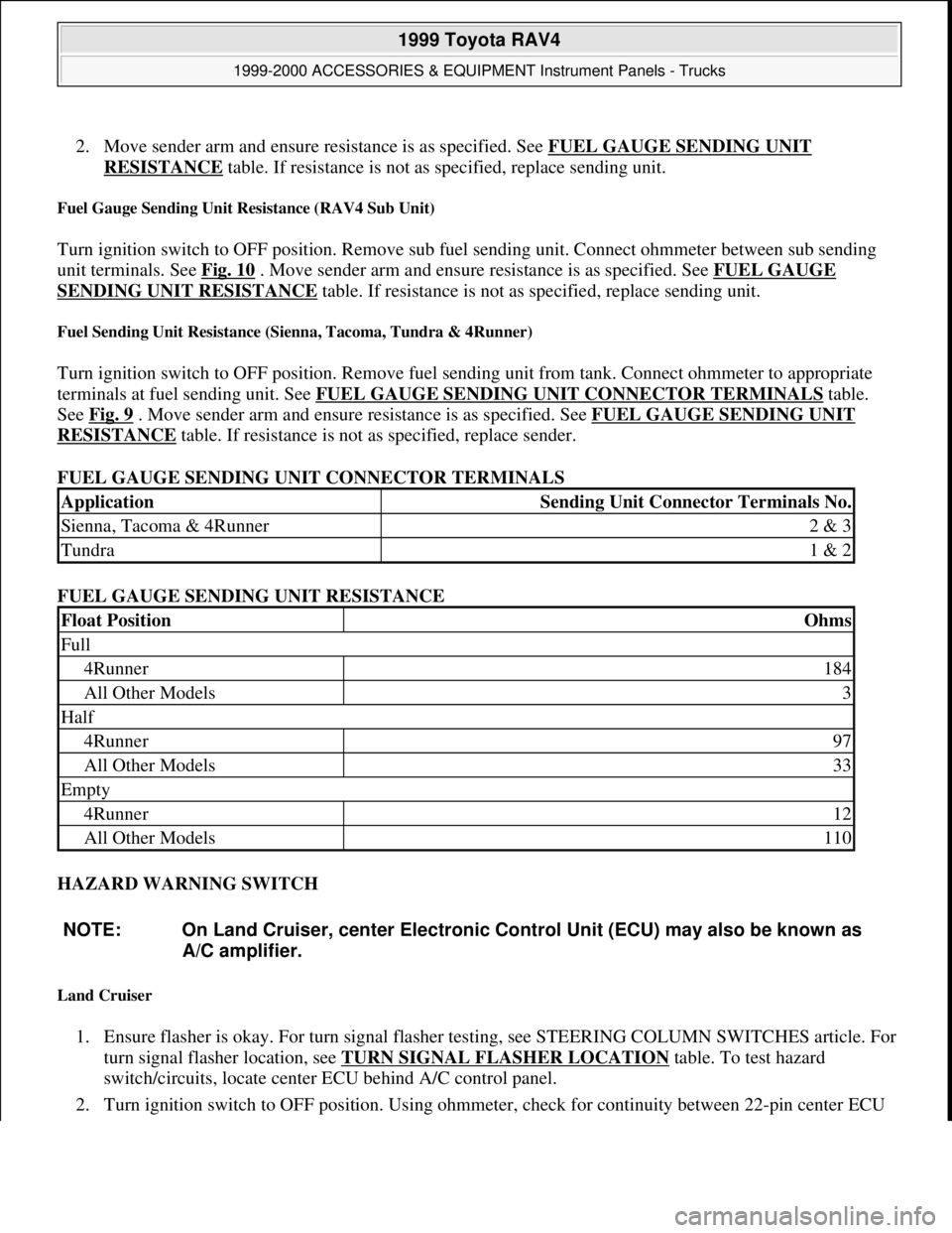
2. Move sender arm and ensure resistance is as specified. See FUEL GAUGE SENDING UNIT
RESISTANCE table. If resistance is not as specified, replace sending unit.
Fuel Gauge Sending Unit Resistance (RAV4 Sub Unit)
Turn ignition switch to OFF position. Remove sub fuel sending unit. Connect ohmmeter between sub sending
unit terminals. See Fig. 10
. Move sender arm and ensure resistance is as specified. See FUEL GAUGE
SENDING UNIT RESISTANCE table. If resistance is not as specified, replace sending unit.
Fuel Sending Unit Resistance (Sienna, Tacoma, Tundra & 4Runner)
Turn ignition switch to OFF position. Remove fuel sending unit from tank. Connect ohmmeter to appropriate
terminals at fuel sending unit. See FUEL GAUGE SENDING UNIT CONNECTOR TERMINALS
table.
See Fig. 9
. Move sender arm and ensure resistance is as specified. See FUEL GAUGE SENDING UNIT
RESISTANCE table. If resistance is not as specified, replace sender.
FUEL GAUGE SENDING UNIT CONNECTOR TERMINALS
FUEL GAUGE SENDING UNIT RESISTANCE
HAZARD WARNING SWITCH
Land Cruiser
1. Ensure flasher is okay. For turn signal flasher testing, see STEERING COLUMN SWITCHES article. For
turn signal flasher location, see TURN SIGNAL FLASHER LOCATION
table. To test hazard
switch/circuits, locate center ECU behind A/C control panel.
2. Turn ignition switch to OFF position. Using ohmmeter, check for continuity between 22-pin center ECU
ApplicationSending Unit Connector Terminals No.
Sienna, Tacoma & 4Runner2 & 3
Tundra1 & 2
Float PositionOhms
Full
4Runner184
All Other Models3
Half
4Runner97
All Other Models33
Empty
4Runner12
All Other Models110
NOTE: On Land Cruiser, center Electronic Control Unit (ECU) may also be known as
A/C amplifier.
1999 Toyota RAV4
1999-2000 ACCESSORIES & EQUIPMENT Instrument Panels - Trucks
Microsoft
Sunday, November 22, 2009 10:54:10 AMPage 19 © 2005 Mitchell Repair Information Company, LLC.
Page 911 of 1632
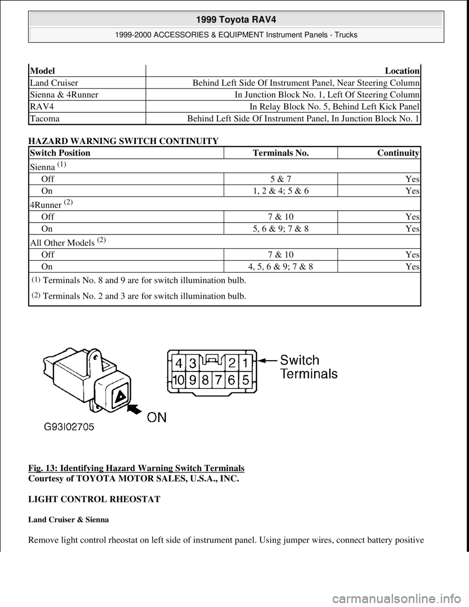
HAZARD WARNING SWITCH CONTINUITY
Fig. 13: Identifying Hazard Warning Switch Terminals
Courtesy of TOYOTA MOTOR SALES, U.S.A., INC.
LIGHT CONTROL RHEOSTAT
Land Cruiser & Sienna
Remove light control rheostat on left side of instrument panel. Using jumper wires, connect battery positive
ModelLocation
Land CruiserBehind Left Side Of Instrument Panel, Near Steering Column
Sienna & 4RunnerIn Junction Block No. 1, Left Of Steering Column
RAV4In Relay Block No. 5, Behind Left Kick Panel
TacomaBehind Left Side Of Instrument Panel, In Junction Block No. 1
Switch PositionTerminals No.Continuity
Sienna (1)
Off5 & 7Yes
On1, 2 & 4; 5 & 6Yes
4Runner (2)
Off7 & 10Yes
On5, 6 & 9; 7 & 8Yes
All Other Models (2)
Off7 & 10Yes
On4, 5, 6 & 9; 7 & 8Yes
(1)Terminals No. 8 and 9 are for switch illumination bulb.
(2)Terminals No. 2 and 3 are for switch illumination bulb.
1999 Toyota RAV4
1999-2000 ACCESSORIES & EQUIPMENT Instrument Panels - Trucks
Microsoft
Sunday, November 22, 2009 10:54:10 AMPage 21 © 2005 Mitchell Repair Information Company, LLC.