transmission oil TOYOTA RAV4 1996 Service Manual Online
[x] Cancel search | Manufacturer: TOYOTA, Model Year: 1996, Model line: RAV4, Model: TOYOTA RAV4 1996Pages: 1632, PDF Size: 41.64 MB
Page 994 of 1632
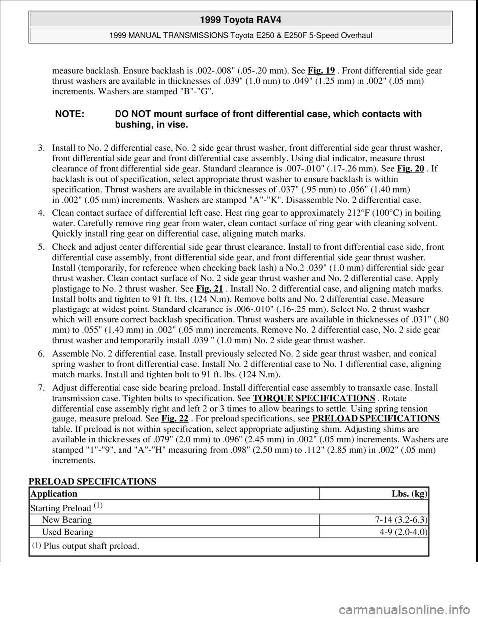
measure backlash. Ensure backlash is .002-.008" (.05-.20 mm). See Fig. 19. Front differential side gear
thrust washers are available in thicknesses of .039" (1.0 mm) to .049" (1.25 mm) in .002" (.05 mm)
increments. Washers are stamped "B"-"G".
3. Install to No. 2 differential case, No. 2 side gear thrust washer, front differential side gear thrust washer,
front differential side gear and front differential case assembly. Using dial indicator, measure thrust
clearance of front differential side gear. Standard clearance is .007-.010" (.17-.26 mm). See Fig. 20
. If
backlash is out of specification, select appropriate thrust washer to ensure backlash is within
specification. Thrust washers are available in thicknesses of .037" (.95 mm) to .056" (1.40 mm)
in .002" (.05 mm) increments. Washers are stamped "A"-"K". Disassemble No. 2 differential case.
4. Clean contact surface of differential left case. Heat ring gear to approximately 212°F (100°C) in boiling
water. Carefully remove ring gear from water, clean contact surface of ring gear with cleaning solvent.
Quickly install ring gear on differential case, aligning match marks.
5. Check and adjust center differential side gear thrust clearance. Install to front differential case side, front
differential case assembly, front differential side gear, and front differential side gear thrust washer.
Install (temporarily, for reference when checking back lash) a No.2 .039" (1.0 mm) differential side gear
thrust washer. Clean contact surface of No. 2 side gear thrust washer and No. 2 differential case. Apply
plastigage to No. 2 thrust washer. See Fig. 21
. Install No. 2 differential case, and aligning match marks.
Install bolts and tighten to 91 ft. lbs. (124 N.m). Remove bolts and No. 2 differential case. Measure
plastigage at widest point. Standard clearance is .006-.010" (.16-.25 mm). Select No. 2 thrust washer
which will ensure correct backlash specification. Thrust washers are available in thicknesses of .031" (.80
mm) to .055" (1.40 mm) in .002" (.05 mm) increments. Remove No. 2 differential case, No. 2 side gear
thrust washer and temporarily install .039 " (1.0 mm) No. 2 side gear thrust washer.
6. Assemble No. 2 differential case. Install previously selected No. 2 side gear thrust washer, and conical
spring washer to front differential case. Install No. 2 differential case to No. 1 differential case, aligning
match marks. Install and tighten bolt to 91 ft. lbs. (124 N.m).
7. Adjust differential case side bearing preload. Install differential case assembly to transaxle case. Install
transmission case. Tighten bolts to specification. See TORQUE SPECIFICATIONS
. Rotate
differential case assembly right and left 2 or 3 times to allow bearings to settle. Using spring tension
gauge, measure preload. See Fig. 22
. For preload specifications, see PRELOAD SPECIFICATIONS
table. If preload is not within specification, select appropriate adjusting shim. Adjusting shims are
available in thicknesses of .079" (2.0 mm) to .096" (2.45 mm) in .002" (.05 mm) increments. Washers are
stamped "1"-"9", and "A"-"H" measuring from .098" (2.50 mm) to .112" (2.85 mm) in .002" (.05 mm)
increments.
PRELOAD SPECIFICATIONS NOTE: DO NOT mount surface of front differential case, which contacts with
bushing, in vise.
ApplicationLbs. (kg)
Starting Preload (1)
New Bearing7-14 (3.2-6.3)
Used Bearing4-9 (2.0-4.0)
(1)Plus output shaft preload.
1999 Toyota RAV4
1999 MANUAL TRANSMISSIONS Toyota E250 & E250F 5-Speed Overhaul
Microsoft
Sunday, November 22, 2009 10:48:07 AMPage 24 © 2005 Mitchell Repair Information Company, LLC.
Page 998 of 1632
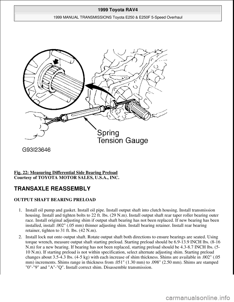
Fig. 22: Measuring Differential Side Bearing Preload
Courtesy of TOYOTA MOTOR SALES, U.S.A., INC.
TRANSAXLE REASSEMBLY
OUTPUT SHAFT BEARING PRELOAD
1. Install oil pump and gasket. Install oil pipe. Install output shaft into clutch housing. Install transmission
housing. Install and tighten bolts to 22 ft. lbs. (29 N.m). Install output shaft rear taper roller bearing outer
race. Install original adjusting shim if output shaft bearing has not been replaced. If new bearing has been
installed, install .002" (.05 mm) thinner adjusting shim. Install bearing retainer. Install rear bearing
retainer, tighten to 31 ft. lbs. (42 N.m).
2. Install lock nut onto output shaft. Rotate output shaft both directions to ensure bearings are seated. Using
torque wrench, measure output shaft starting preload. Starting preload should be 6.9-13.9 INCH lbs. (8-16
N.m) for a new bearing. If bearing has not been replaced, starting preload should be 4.3-8.7 INCH lbs. (5-
10 N.m). If starting preload is not within specification, select alternate adjusting shim. Starting preload
changes about 3.5-4.3 lbs. (4-5 kg) with each increase of shim thickness. Shims are available in .002" (.05
mm) increments. Shims range in thickness from .051" (1.30 mm) to .098" (2.50 mm). Shims are stamped
"0"-"9" and "A"-"Q". Install correct shim. Disassemble transmission.
1999 Toyota RAV4
1999 MANUAL TRANSMISSIONS Toyota E250 & E250F 5-Speed Overhaul
Microsoft
Sunday, November 22, 2009 10:48:07 AMPage 28 © 2005 Mitchell Repair Information Company, LLC.
Page 999 of 1632
REASSEMBLY
1. Assembly is reverse order of disassembly. Remove output shaft. Install oil pump drive gear. Install input
and output shaft assemblies, and shift fork assemblies as single unit. Install shift fork shaft locking balls,
springs, seats and plugs. Install reverse idler gear and shaft. Align referencing marks on idler gear and
clutch housing. Place reverse shift fork pivot into reverse shift arm, and install reverse shift arm bracket to
clutch housing. Install No. 2 oil pipe. Install NEW gasket to oil pipe. See Fig. 1
.
2. Apply Three Bond (1281) sealant to transmission housing. Install transmission housing to clutch housing.
Install reverse idler gear shaft retaining bolt. Install shift shaft locking ball, spring, seat and plug. Install
snap rings onto shift fork shafts.
3. Install output shaft rear bearing outer race. Install correct adjusting shim. Install snap ring onto input shaft
rear bearing. Install rear bearing retainer. Install spacer, needle bearing and 5th gear. Install synchro ring
and key spring to No. 3 clutch hub. Using Installer (09310-17010), install No. 3 clutch hub with
synchronizer ring and key spring. See Fig. 2
.
4. Select a snap ring that will allow minimum axial play and install snap ring onto shaft. Snap rings are
available in thicknesses of .068" (1.75 mm) to .084" (2.15 mm) in .002" (.05 mm) increments. Shims are
stamped "A"-"J". See Fig. 2
.
5. Recheck 5th gear thrust clearance. Standard clearance is .004-.022" (.10-.57 mm). Install 5th driven gear.
Install No. 3 hub sleeve and No. 3 shift fork. Lock transmission in 2 gears. Install and tighten NEW lock
nut to 90 ft. lbs. (123 N.m). Stake lock nut. Unlock transmission.
6. Apply Three Bond (1281) sealant to transmission case cover. Install cover. Install shift and select lever
shaft. Install control shaft cover. Install lock bolt. Install boot onto control shaft oil seal. Ensure boot is
installed in correct direction. Position air bleed of boot downward. Install selecting bellcrank. Install
back-up light switch and speedometer driven gear. Install side gear intermediate shaft. Distance from end
of shaft to clutch housing should be 10.06" (255.5 mm).
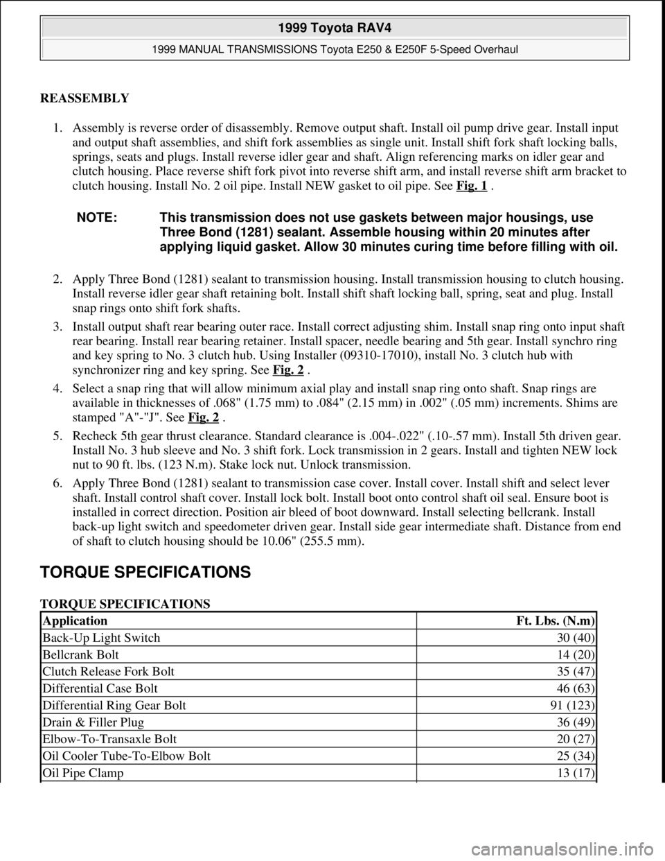
TORQUE SPECIFICATIONS
TORQUE SPECIFICATIONS NOTE: This transmission does not use gaskets between major housings, use
Three Bond (1281) sealant. Assemble housing within 20 minutes after
applying liquid gasket. Allow 30 minutes curing time before filling with oil.
ApplicationFt. Lbs. (N.m)
Back-Up Light Switch30 (40)
Bellcrank Bolt14 (20)
Clutch Release Fork Bolt35 (47)
Differential Case Bolt46 (63)
Differential Ring Gear Bolt91 (123)
Drain & Filler Plug36 (49)
Elbow-To-Transaxle Bolt20 (27)
Oil Cooler Tube-To-Elbow Bolt25 (34)
Oil Pipe Clamp13 (17)
1999 Toyota RAV4
1999 MANUAL TRANSMISSIONS Toyota E250 & E250F 5-Speed Overhaul
Microsoft
Sunday, November 22, 2009 10:48:07 AMPage 29 © 2005 Mitchell Repair Information Company, LLC.
Page 1000 of 1632
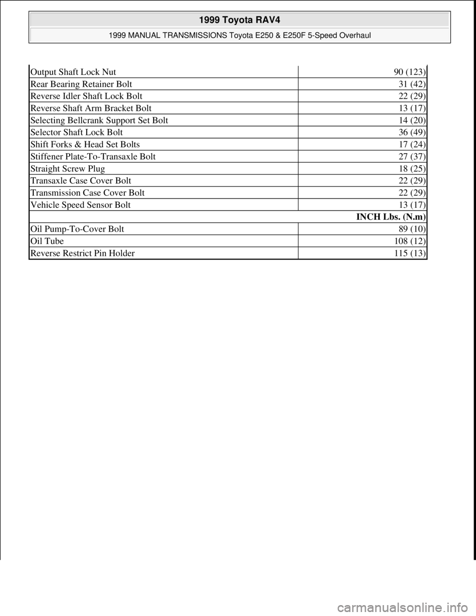
Output Shaft Lock Nut90 (123)
Rear Bearing Retainer Bolt31 (42)
Reverse Idler Shaft Lock Bolt22 (29)
Reverse Shaft Arm Bracket Bolt13 (17)
Selecting Bellcrank Support Set Bolt14 (20)
Selector Shaft Lock Bolt36 (49)
Shift Forks & Head Set Bolts17 (24)
Stiffener Plate-To-Transaxle Bolt27 (37)
Straight Screw Plug18 (25)
Transaxle Case Cover Bolt22 (29)
Transmission Case Cover Bolt22 (29)
Vehicle Speed Sensor Bolt13 (17)
INCH Lbs. (N.m)
Oil Pump-To-Cover Bolt89 (10)
Oil Tube108 (12)
Reverse Restrict Pin Holder115 (13)
1999 Toyota RAV4
1999 MANUAL TRANSMISSIONS Toyota E250 & E250F 5-Speed Overhaul
Microsoft
Sunday, November 22, 2009 10:48:07 AMPage 30 © 2005 Mitchell Repair Information Company, LLC.
Page 1002 of 1632
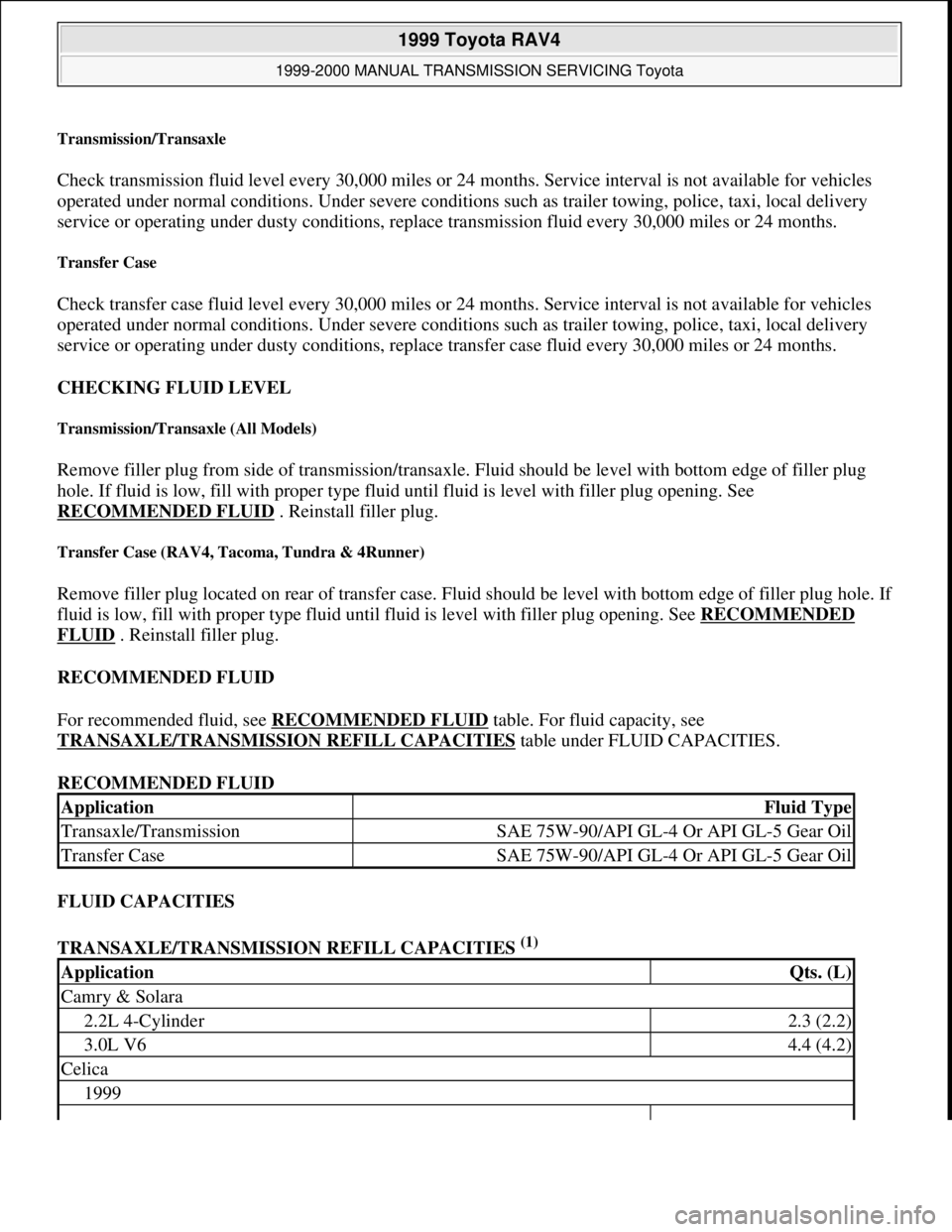
Transmission/Transaxle
Check transmission fluid level every 30,000 miles or 24 months. Service interval is not available for vehicles
operated under normal conditions. Under severe conditions such as trailer towing, police, taxi, local delivery
service or operating under dusty conditions, replace transmission fluid every 30,000 miles or 24 months.
Transfer Case
Check transfer case fluid level every 30,000 miles or 24 months. Service interval is not available for vehicles
operated under normal conditions. Under severe conditions such as trailer towing, police, taxi, local delivery
service or operating under dusty conditions, replace transfer case fluid every 30,000 miles or 24 months.
CHECKING FLUID LEVEL
Transmission/Transaxle (All Models)
Remove filler plug from side of transmission/transaxle. Fluid should be level with bottom edge of filler plug
hole. If fluid is low, fill with proper type fluid until fluid is level with filler plug opening. See
RECOMMENDED FLUID
. Reinstall filler plug.
Transfer Case (RAV4, Tacoma, Tundra & 4Runner)
Remove filler plug located on rear of transfer case. Fluid should be level with bottom edge of filler plug hole. If
fluid is low, fill with proper type fluid until fluid is level with filler plug opening. See RECOMMENDED
FLUID . Reinstall filler plug.
RECOMMENDED FLUID
For recommended fluid, see RECOMMENDED FLUID
table. For fluid capacity, see
TRANSAXLE/TRANSMISSION REFILL CAPACITIES
table under FLUID CAPACITIES.
RECOMMENDED FLUID
FLUID CAPACITIES
TRANSAXLE/TRANSMISSION REFILL CAPACITIES
(1)
ApplicationFluid Type
Transaxle/TransmissionSAE 75W-90/API GL-4 Or API GL-5 Gear Oil
Transfer CaseSAE 75W-90/API GL-4 Or API GL-5 Gear Oil
ApplicationQts. (L)
Camry & Solara
2.2L 4-Cylinder2.3 (2.2)
3.0L V64.4 (4.2)
Celica
1999
1999 Toyota RAV4
1999-2000 MANUAL TRANSMISSION SERVICING Toyota
Microsoft
Sunday, November 22, 2009 10:47:31 AMPage 2 © 2005 Mitchell Repair Information Company, LLC.
Page 1266 of 1632
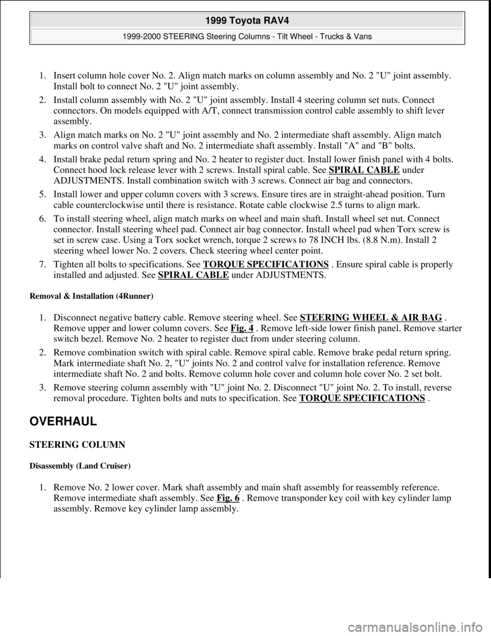
1. Insert column hole cover No. 2. Align match marks on column assembly and No. 2 "U" joint assembly.
Install bolt to connect No. 2 "U" joint assembly.
2. Install column assembly with No. 2 "U" joint assembly. Install 4 steering column set nuts. Connect
connectors. On models equipped with A/T, connect transmission control cable assembly to shift lever
assembly.
3. Align match marks on No. 2 "U" joint assembly and No. 2 intermediate shaft assembly. Align match
marks on control valve shaft and No. 2 intermediate shaft assembly. Install "A" and "B" bolts.
4. Install brake pedal return spring and No. 2 heater to register duct. Install lower finish panel with 4 bolts.
Connect hood lock release lever with 2 screws. Install spiral cable. See SPIRAL CABLE
under
ADJUSTMENTS. Install combination switch with 3 screws. Connect air bag and connectors.
5. Install lower and upper column covers with 3 screws. Ensure tires are in straight-ahead position. Turn
cable counterclockwise until there is resistance. Rotate cable clockwise 2.5 turns to align mark.
6. To install steering wheel, align match marks on wheel and main shaft. Install wheel set nut. Connect
connector. Install steering wheel pad. Connect air bag connector. Install wheel pad when Torx screw is
set in screw case. Using a Torx socket wrench, torque 2 screws to 78 INCH lbs. (8.8 N.m). Install 2
steering wheel lower No. 2 covers. Check steering wheel center point.
7. Tighten all bolts to specifications. See TORQUE SPECIFICATIONS
. Ensure spiral cable is properly
installed and adjusted. See SPIRAL CABLE
under ADJUSTMENTS.
Removal & Installation (4Runner)
1. Disconnect negative battery cable. Remove steering wheel. See STEERING WHEEL & AIR BAG .
Remove upper and lower column covers. See Fig. 4
. Remove left-side lower finish panel. Remove starter
switch bezel. Remove No. 2 heater to register duct from under steering column.
2. Remove combination switch with spiral cable. Remove spiral cable. Remove brake pedal return spring.
Mark intermediate shaft No. 2, "U" joints No. 2 and control valve for installation reference. Remove
intermediate shaft No. 2 and bolts. Remove column hole cover and column hole cover No. 2 set bolt.
3. Remove steering column assembly with "U" joint No. 2. Disconnect "U" joint No. 2. To install, reverse
removal procedure. Tighten bolts and nuts to specification. See TORQUE SPECIFICATIONS
.
OVERHAUL
STEERING COLUMN
Disassembly (Land Cruiser)
1. Remove No. 2 lower cover. Mark shaft assembly and main shaft assembly for reassembly reference.
Remove intermediate shaft assembly. See Fig. 6
. Remove transponder key coil with key cylinder lamp
assembly. Remove key cylinder lamp assembly.
1999 Toyota RAV4
1999-2000 STEERING Steering Columns - Tilt Wheel - Trucks & Vans
Microsoft
Sunday, November 22, 2009 10:34:02 AMPage 12 © 2005 Mitchell Repair Information Company, LLC.