clutch TOYOTA RAV4 1996 Service Repair Manual
[x] Cancel search | Manufacturer: TOYOTA, Model Year: 1996, Model line: RAV4, Model: TOYOTA RAV4 1996Pages: 1632, PDF Size: 41.64 MB
Page 113 of 1632
TRANSMISSION SERVICING - A/T
1997-98 TRANSMISSION SERVICING Toyota - Transmission Removal & Installation
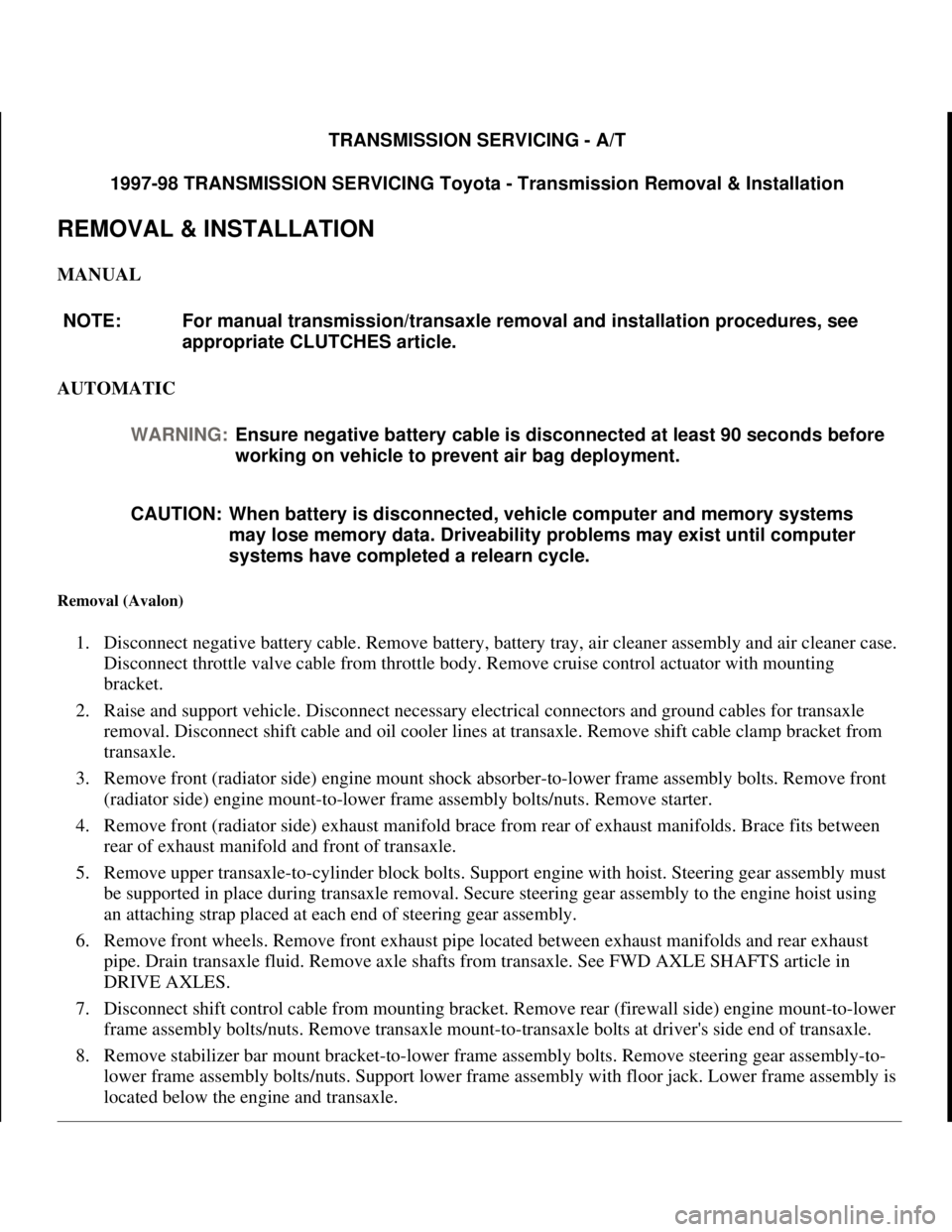
REMOVAL & INSTALLATION
MANUAL
AUTOMATIC
Removal (Avalon)
1. Disconnect negative battery cable. Remove battery, battery tray, air cleaner assembly and air cleaner case.
Disconnect throttle valve cable from throttle body. Remove cruise control actuator with mounting
bracket.
2. Raise and support vehicle. Disconnect necessary electrical connectors and ground cables for transaxle
removal. Disconnect shift cable and oil cooler lines at transaxle. Remove shift cable clamp bracket from
transaxle.
3. Remove front (radiator side) engine mount shock absorber-to-lower frame assembly bolts. Remove front
(radiator side) engine mount-to-lower frame assembly bolts/nuts. Remove starter.
4. Remove front (radiator side) exhaust manifold brace from rear of exhaust manifolds. Brace fits between
rear of exhaust manifold and front of transaxle.
5. Remove upper transaxle-to-cylinder block bolts. Support engine with hoist. Steering gear assembly must
be supported in place during transaxle removal. Secure steering gear assembly to the engine hoist using
an attaching strap placed at each end of steering gear assembly.
6. Remove front wheels. Remove front exhaust pipe located between exhaust manifolds and rear exhaust
pipe. Drain transaxle fluid. Remove axle shafts from transaxle. See FWD AXLE SHAFTS article in
DRIVE AXLES.
7. Disconnect shift control cable from mounting bracket. Remove rear (firewall side) engine mount-to-lower
frame assembly bolts/nuts. Remove transaxle mount-to-transaxle bolts at driver's side end of transaxle.
8. Remove stabilizer bar mount bracket-to-lower frame assembly bolts. Remove steering gear assembly-to-
lower frame assembly bolts/nuts. Support lower frame assembly with floor jack. Lower frame assembly is
located below the en
gine and transaxle. NOTE: For manual transmission/transaxle removal and installation procedures, see
appropriate CLUTCHES article.
WARNING:Ensure negative battery cable is disconnected at least 90 seconds before
working on vehicle to prevent air bag deployment.
CAUTION: When battery is disconnected, vehicle computer and memory systems
may lose memory data. Driveability problems may exist until computer
systems have completed a relearn cycle.
1998 Toyota Avalon XLS
TRANSMISSION SERVICING - A/T 1997-98 TRANSMISSION SERVICING Toyota - Transmission Removal &
Installation
1998 Toyota Avalon XLS
TRANSMISSION SERVICING - A/T 1997-98 TRANSMISSION SERVICING Toyota - Transmission Removal &
Installation
Helpmelearn
November-03-08 10:30:28 AMPage 1 © 2005 Mitchell Repair Information Company, LLC.
Helpmelearn
November-03-08 10:30:32 AMPage 1 © 2005 Mitchell Repair Information Company, LLC.
Page 128 of 1632

clutch, fan shroud and radiator. Remove transmission dipstick. Remove dipstick tube upper bolt.
Disconnect 2 bleeder hoses.
2. Remove knob from transfer case shift lever. Remove upper console panel. Remove 4 boots to transfer
shift lever boot and remove shift lever boot. Raise and support vehicle. Remove 2 lower engine covers.
Remove exhaust pipes as necessary. Place reference marks on drive shaft flanges for reassembly
reference. Remove bolts and all drive shafts.
3. Remove dipstick tube lower bolt. Remove dipstick tube and "O" ring. Remove nut and plate washer, and
disconnect transmission shift control rod. Remove clip, plate washer and collar, and disconnect transfer
shift lever rod assembly. Disconnect all necessary electrical connectors for transmission and transfer case
removal. Remove 2 bolts and cover from front of transmission for access to torque converter bolts.
Remove torque converter bolts. Remove oil cooler pipe union nuts and pipe bracket bolt from
transmission.
4. Support transmission with transmission jack. Remove 8 bolts and 2 nuts from crossmember and remove
crossmember. Lower rear of transmission. Remove transmission wire clamp bolt. Remove 10
transmission-to-cylinder block bolts. Lower transmission with transfer case from vehicle.
Installation
1. Before installing transmission, use dial indicator to check drive plate runout. Drive plate runout should be
checked right next to the starter ring gear on the drive plate. Replace drive plate if runout
exceeds .0079" (.200 mm).
2. Install torque converter on transmission. To ensure torque converter is fully seated, torque converter
depth should be checked. Using straightedge and caliper, measure torque converter depth from torque
converter bolt lug on torque converter to the surface on transmission. See Fig. 1
.
3. Torque converter depth should be more than .673" (17.10 mm). If torque converter depth is less than
specified, check for improperly seated torque converter.
4. To install, reverse removal procedure. Tighten all bolts/nuts to specification. See TORQUE
SPECIFICATIONS When installing torque converter bolts, apply Loctite to torque converter bolt
threads before installing. Ensure the Green torque converter bolt is installed first before installing the
remaining torque converter bolts.
5. Install NEW "O" ring on dipstick tube. Use NEW gaskets and NEW nuts when installing front exhaust
pipe. Fill cooling system and check for leaks. Adjust shift linkages and fill with ATF. See appropriate
TRANSMISSION SERVICING article.
Removal (Paseo)
1. Disconnect negative battery cable. Remove transaxle oil dipstick. Disconnect throttle valve cable from
throttle body. Remove air cleaner assembly along with air intake duct to air cleaner.
2. Remove upper bolt from starter. Remove the 2 upper transaxle-to-cylinder block bolts located at top of
transaxle. Raise and support vehicle. Remove lower engine covers.
3. Support engine with hoist. Remove front wheels. Drain transaxle fluid. Remove axle shafts from
transaxle. See FWD AXLE SHAFTS article in DRIVE AXLES.
4. Disconnect necessary electrical connectors, ground cables, speedometer cable, control cables and oil
cooler lines for transaxle removal. Remove the 2 vertical bottom bolts from front (radiator side) transaxle
mount.
1998 Toyota Avalon XLS
TRANSMISSION SERVICING - A/T 1997-98 TRANSMISSION SERVICING Toyota - Transmission Removal &
Installation
Helpmelearn
November-03-08 10:30:28 AMPage 16 © 2005 Mitchell Repair Information Company, LLC.
Page 156 of 1632
DESCRIPTION
The A-540H 4WD transaxle has a center differential and electronic transfer case attached. Transaxle internal
components are the same or similar to the A-540E and A-541E transaxles. Transaxle has 4 shift solenoids in the
valve body to control engagement speed and throttle pressure for shift feel. Torque is distributed to front and
rear wheels at all times to maximize traction of 4WD vehicle.
The A-540E and A-541E transaxles feature a torque converter with lock-up clutch, 4-speed planetary gear unit,
differential, hydraulic control system, shift solenoids and electronic control system. The A-541E transaxle has
an additional shift solenoid in the valve body to control engagement speed and throttle pressure for shift feel. A
shift lock mechanism is used to minimize possibility of incorrect operation of transaxle.
LUBRICATION
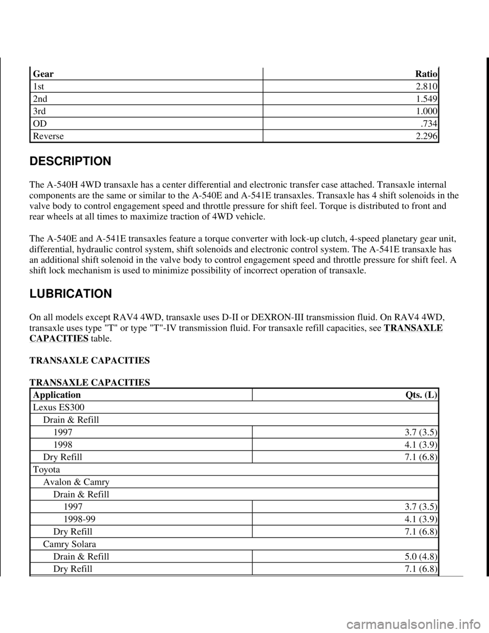
On all models except RAV4 4WD, transaxle uses D-II or DEXRON-III transmission fluid. On RAV4 4WD,
transaxle uses type "T" or type "T"-IV transmission fluid. For transaxle refill capacities, see TRANSAXLE
CAPACITIES table.
TRANSAXLE CAPACITIES
TRANSAXLE CAPACITIES
GearRatio
1st2.810
2nd1.549
3rd1.000
OD.734
Reverse2.296
ApplicationQts. (L)
Lexus ES300
Drain & Refill
19973.7 (3.5)
19984.1 (3.9)
Dry Refill7.1 (6.8)
Toyota
Avalon & Camry
Drain & Refill
19973.7 (3.5)
1998-994.1 (3.9)
Dry Refill7.1 (6.8)
Camry Solara
Drain & Refill5.0 (4.8)
Dry Refill7.1 (6.8)
1998 Toyota Avalon XLS
1997-99 AUTOMATIC TRANSMISSIONS Toyota A-540E, A-540H & A-541E Overhaul
Helpmelearn
November-03-08 10:28:16 AMPage 2 © 2005 Mitchell Repair Information Company, LLC.
Page 160 of 1632
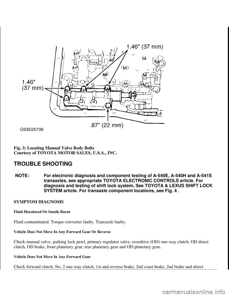
Fig. 3: Locating Manual Valve Body Bolts
Courtesy of TOYOTA MOTOR SALES, U.S.A., INC.
TROUBLE SHOOTING
SYMPTOM DIAGNOSIS
Fluid Discolored Or Smells Burnt
Fluid contaminated. Torque converter faulty. Transaxle faulty.
Vehicle Does Not Move In Any Forward Gear Or Reverse
Check manual valve, parking lock pawl, primary regulator valve, overdrive (OD) one-way clutch, OD direct
clutch, OD brake, front planetary gear, rear planetary gear and OD planetary gear.
Vehicle Does Not Move In Any Forward Gear
Check forward clutch, No. 2 one-way clutch, 1st and reverse brake, 2nd coast brake, 2nd brake and direct
NOTE: For electronic diagnosis and component testing of A-540E, A-540H and A-541E
transaxles, see appropriate TOYOTA ELECTRONIC CONTROLS article. For
diagnosis and testing of shift lock system, See TOYOTA & LEXUS SHIFT LOCK
SYSTEM article. For transaxle component locations, see Fig. 4
.
1998 Toyota Avalon XLS
1997-99 AUTOMATIC TRANSMISSIONS Toyota A-540E, A-540H & A-541E Overhaul
Helpmelearn
November-03-08 10:28:16 AMPage 6 © 2005 Mitchell Repair Information Company, LLC.
Page 161 of 1632
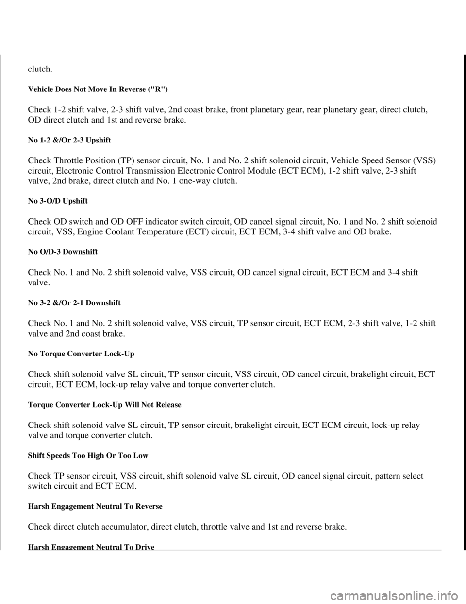
clutch.
Vehicle Does Not Move In Reverse ("R")
Check 1-2 shift valve, 2-3 shift valve, 2nd coast brake, front planetary gear, rear planetary gear, direct clutch,
OD direct clutch and 1st and reverse brake.
No 1-2 &/Or 2-3 Upshift
Check Throttle Position (TP) sensor circuit, No. 1 and No. 2 shift solenoid circuit, Vehicle Speed Sensor (VSS)
circuit, Electronic Control Transmission Electronic Control Module (ECT ECM), 1-2 shift valve, 2-3 shift
valve, 2nd brake, direct clutch and No. 1 one-way clutch.
No 3-O/D Upshift
Check OD switch and OD OFF indicator switch circuit, OD cancel signal circuit, No. 1 and No. 2 shift solenoid
circuit, VSS, Engine Coolant Temperature (ECT) circuit, ECT ECM, 3-4 shift valve and OD brake.
No O/D-3 Downshift
Check No. 1 and No. 2 shift solenoid valve, VSS circuit, OD cancel signal circuit, ECT ECM and 3-4 shift
valve.
No 3-2 &/Or 2-1 Downshift
Check No. 1 and No. 2 shift solenoid valve, VSS circuit, TP sensor circuit, ECT ECM, 2-3 shift valve, 1-2 shift
valve and 2nd coast brake.
No Torque Converter Lock-Up
Check shift solenoid valve SL circuit, TP sensor circuit, VSS circuit, OD cancel circuit, brakelight circuit, ECT
circuit, ECT ECM, lock-up relay valve and torque converter clutch.
Torque Converter Lock-Up Will Not Release
Check shift solenoid valve SL circuit, TP sensor circuit, brakelight circuit, ECT ECM circuit, lock-up relay
valve and torque converter clutch.
Shift Speeds Too High Or Too Low
Check TP sensor circuit, VSS circuit, shift solenoid valve SL circuit, OD cancel signal circuit, pattern select
switch circuit and ECT ECM.
Harsh Engagement Neutral To Reverse
Check direct clutch accumulator, direct clutch, throttle valve and 1st and reverse brake.
Harsh Engagement Neutral To Drive
1998 Toyota Avalon XLS
1997-99 AUTOMATIC TRANSMISSIONS Toyota A-540E, A-540H & A-541E Overhaul
Helpmelearn
November-03-08 10:28:16 AMPage 7 © 2005 Mitchell Repair Information Company, LLC.
Page 162 of 1632
Check forward clutch accumulator, throttle valve and forward clutch.
No Engine Braking In Low
Check low coast modulator valve and 1st and reverse brake.
No Engine Braking In 2nd
Check 2nd coast modulator valve and 2nd coast brake.
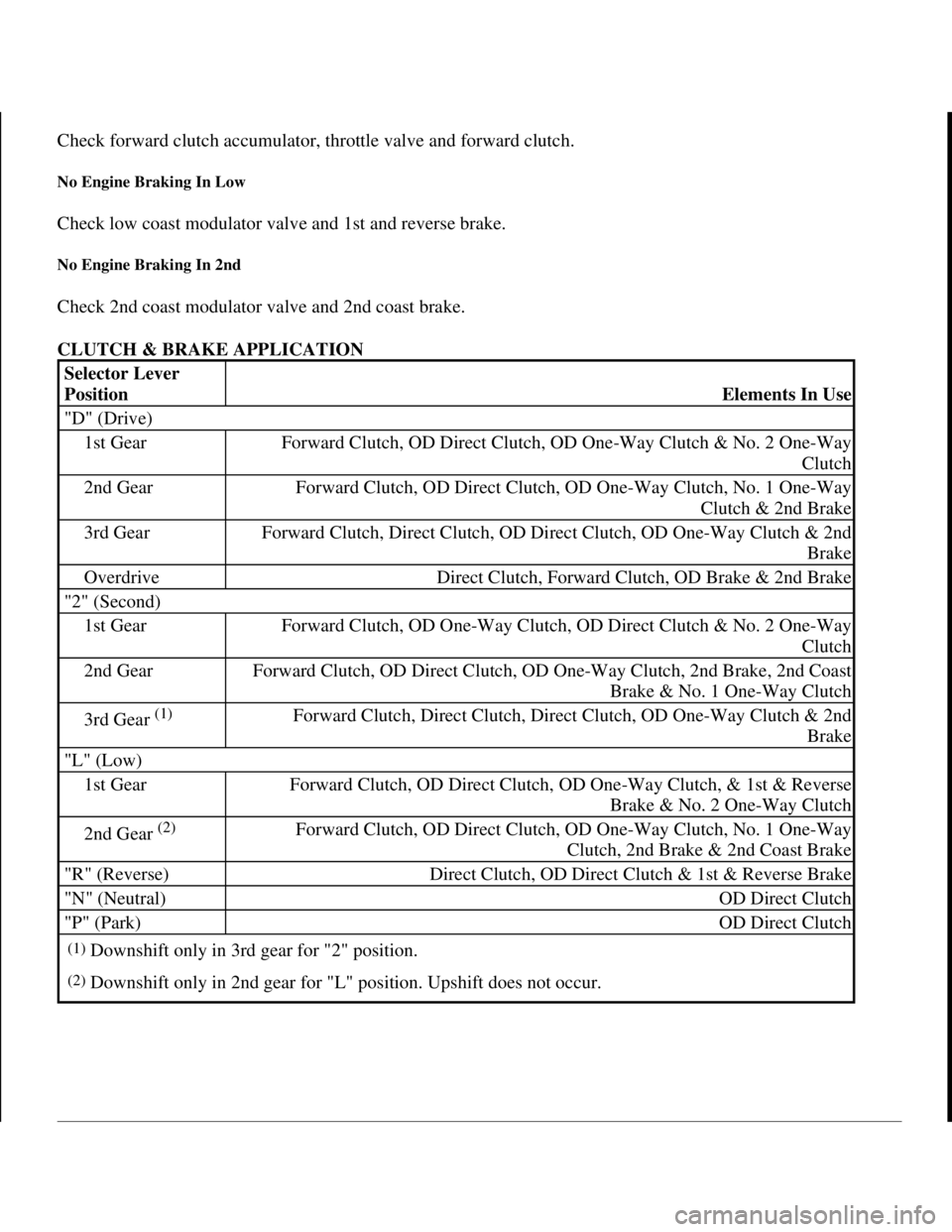
CLUTCH & BRAKE APPLICATION
Selector Lever
Position
Elements In Use
"D" (Drive)
1st GearForward Clutch, OD Direct Clutch, OD One-Way Clutch & No. 2 One-Way
Clutch
2nd GearForward Clutch, OD Direct Clutch, OD One-Way Clutch, No. 1 One-Way
Clutch & 2nd Brake
3rd GearForward Clutch, Direct Clutch, OD Direct Clutch, OD One-Way Clutch & 2nd
Brake
OverdriveDirect Clutch, Forward Clutch, OD Brake & 2nd Brake
"2" (Second)
1st GearForward Clutch, OD One-Way Clutch, OD Direct Clutch & No. 2 One-Way
Clutch
2nd GearForward Clutch, OD Direct Clutch, OD One-Way Clutch, 2nd Brake, 2nd Coast
Brake & No. 1 One-Way Clutch
3rd Gear (1)Forward Clutch, Direct Clutch, Direct Clutch, OD One-Way Clutch & 2nd
Brake
"L" (Low)
1st GearForward Clutch, OD Direct Clutch, OD One-Way Clutch, & 1st & Reverse
Brake & No. 2 One-Way Clutch
2nd Gear (2)Forward Clutch, OD Direct Clutch, OD One-Way Clutch, No. 1 One-Way
Clutch, 2nd Brake & 2nd Coast Brake
"R" (Reverse)Direct Clutch, OD Direct Clutch & 1st & Reverse Brake
"N" (Neutral)OD Direct Clutch
"P" (Park)OD Direct Clutch
(1)Downshift only in 3rd gear for "2" position.
(2)Downshift only in 2nd gear for "L" position. Upshift does not occur.
1998 Toyota Avalon XLS
1997-99 AUTOMATIC TRANSMISSIONS Toyota A-540E, A-540H & A-541E Overhaul
Helpmelearn
November-03-08 10:28:17 AMPage 8 © 2005 Mitchell Repair Information Company, LLC.
Page 164 of 1632
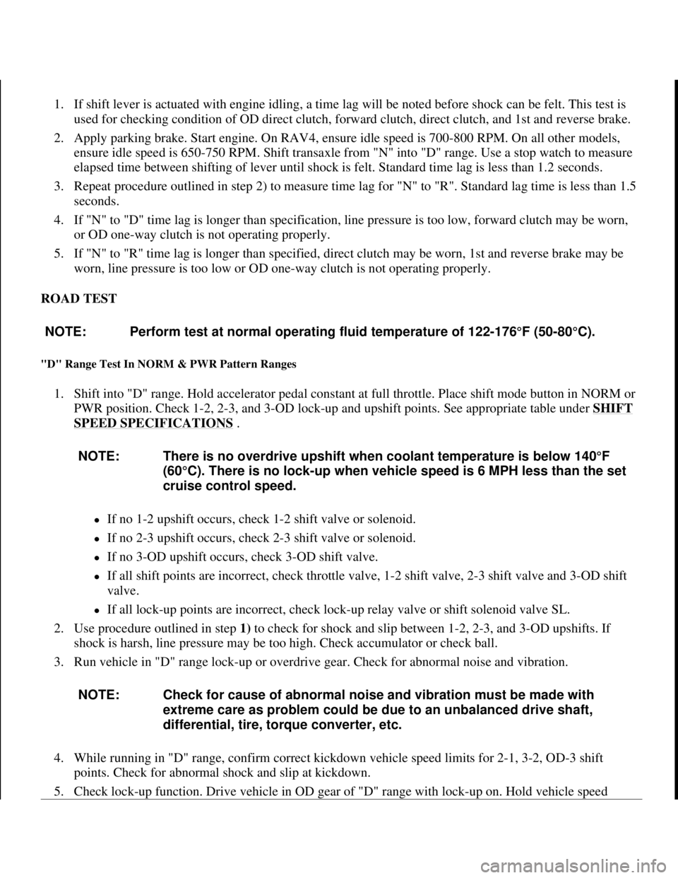
1. If shift lever is actuated with engine idling, a time lag will be noted before shock can be felt. This test is
used for checking condition of OD direct clutch, forward clutch, direct clutch, and 1st and reverse brake.
2. Apply parking brake. Start engine. On RAV4, ensure idle speed is 700-800 RPM. On all other models,
ensure idle speed is 650-750 RPM. Shift transaxle from "N" into "D" range. Use a stop watch to measure
elapsed time between shifting of lever until shock is felt. Standard time lag is less than 1.2 seconds.
3. Repeat procedure outlined in step 2) to measure time lag for "N" to "R". Standard lag time is less than 1.5
seconds.
4. If "N" to "D" time lag is longer than specification, line pressure is too low, forward clutch may be worn,
or OD one-way clutch is not operating properly.
5. If "N" to "R" time lag is longer than specified, direct clutch may be worn, 1st and reverse brake may be
worn, line pressure is too low or OD one-way clutch is not operating properly.
ROAD TEST
"D" Range Test In NORM & PWR Pattern Ranges
1. Shift into "D" range. Hold accelerator pedal constant at full throttle. Place shift mode button in NORM or
PWR position. Check 1-2, 2-3, and 3-OD lock-up and upshift points. See appropriate table under SHIFT
SPEED SPECIFICATIONS .
zIf no 1-2 upshift occurs, check 1-2 shift valve or solenoid.
zIf no 2-3 upshift occurs, check 2-3 shift valve or solenoid.
zIf no 3-OD upshift occurs, check 3-OD shift valve.
zIf all shift points are incorrect, check throttle valve, 1-2 shift valve, 2-3 shift valve and 3-OD shift
valve.
zIf all lock-up points are incorrect, check lock-up relay valve or shift solenoid valve SL.
2. Use procedure outlined in step 1) to check for shock and slip between 1-2, 2-3, and 3-OD upshifts. If
shock is harsh, line pressure may be too high. Check accumulator or check ball.
3. Run vehicle in "D" range lock-up or overdrive gear. Check for abnormal noise and vibration.
4. While running in "D" range, confirm correct kickdown vehicle speed limits for 2-1, 3-2, OD-3 shift
points. Check for abnormal shock and slip at kickdown.
5. Check loc
k-up function. Drive vehicle in OD gear of "D" range with lock-up on. Hold vehicle speed NOTE: Perform test at normal operating fluid temperature of 122-176°F (50-80°C).
NOTE: There is no overdrive upshift when coolant temperature is below 140°F
(60°C). There is no lock-up when vehicle speed is 6 MPH less than the set
cruise control speed.
NOTE: Check for cause of abnormal noise and vibration must be made with
extreme care as problem could be due to an unbalanced drive shaft,
differential, tire, torque converter, etc.
1998 Toyota Avalon XLS
1997-99 AUTOMATIC TRANSMISSIONS Toyota A-540E, A-540H & A-541E Overhaul
Helpmelearn
November-03-08 10:28:17 AMPage 10 © 2005 Mitchell Repair Information Company, LLC.
Page 170 of 1632
STALL SPEED TEST
1. Object of test is to check overall performance of transaxle and engine by measuring maximum stall
speeds in "D" and "R" ranges.
2. Block front and rear wheels. Connect scan tool to DLC3, located under instrument panel. Apply parking
and service brakes. Start engine. Position transmission in "D" range. Fully depress accelerator pedal.
Immediately note highest engine RPM. DO NOT perform test longer than 5 seconds. Repeat test in "R"
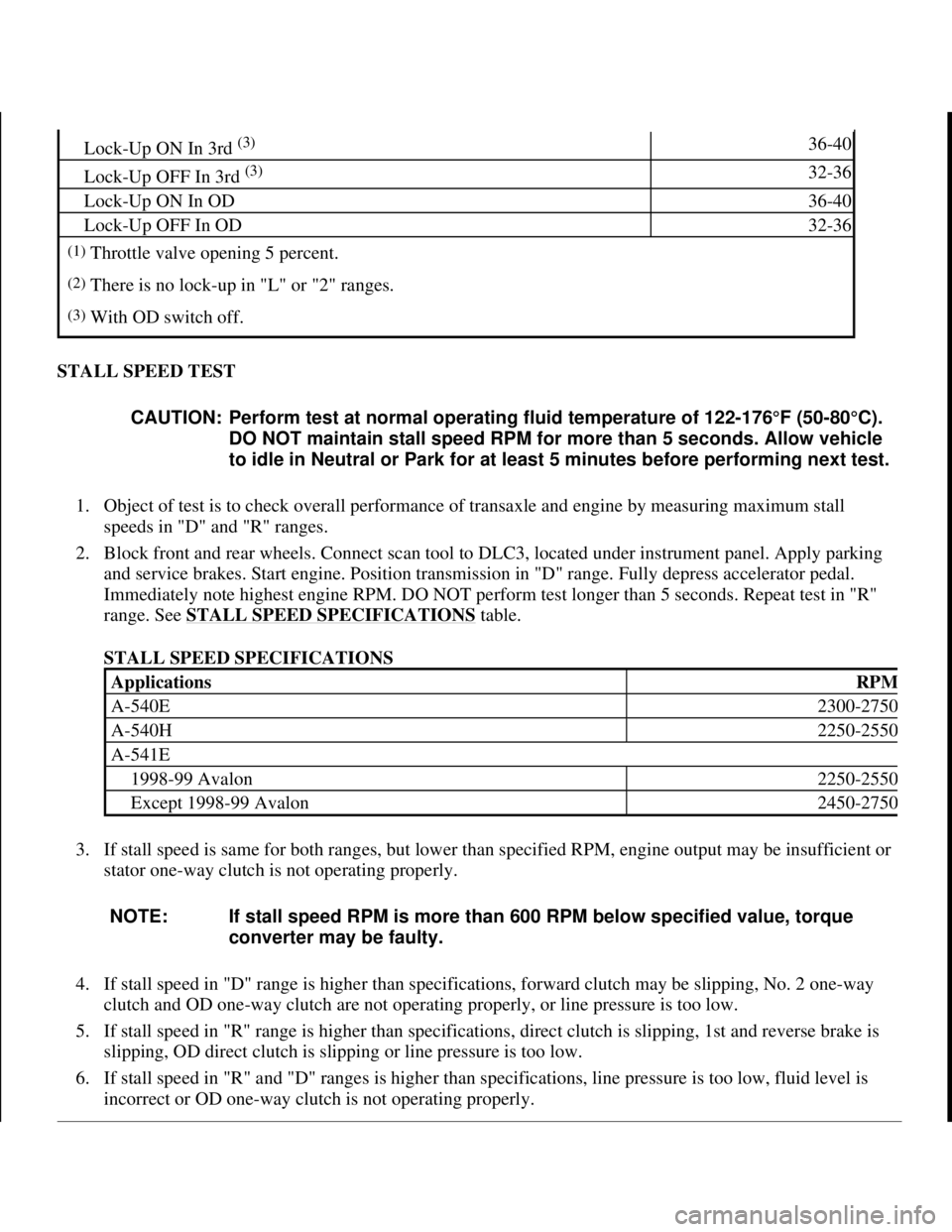
range. See STALL SPEED SPECIFICATIONS
table.
STALL SPEED SPECIFICATIONS
3. If stall speed is same for both ranges, but lower than specified RPM, engine output may be insufficient or
stator one-way clutch is not operating properly.
4. If stall speed in "D" range is higher than specifications, forward clutch may be slipping, No. 2 one-way
clutch and OD one-way clutch are not operating properly, or line pressure is too low.
5. If stall speed in "R" range is higher than specifications, direct clutch is slipping, 1st and reverse brake is
slipping, OD direct clutch is slipping or line pressure is too low.
6. If stall speed in "R" and "D" ranges is higher than specifications, line pressure is too low, fluid level is
incorrect or OD one-wa
y clutch is not operating properly.
Lock-Up ON In 3rd (3)36-40
Lock-Up OFF In 3rd (3)32-36
Lock-Up ON In OD36-40
Lock-Up OFF In OD32-36
(1)Throttle valve opening 5 percent.
(2)There is no lock-up in "L" or "2" ranges.
(3)With OD switch off.
CAUTION: Perform test at normal operating fluid temperature of 122-176°F (50-80°C).
DO NOT maintain stall speed RPM for more than 5 seconds. Allow vehicle
to idle in Neutral or Park for at least 5 minutes before performing next test.
ApplicationsRPM
A-540E2300-2750
A-540H2250-2550
A-541E
1998-99 Avalon2250-2550
Except 1998-99 Avalon2450-2750
NOTE: If stall speed RPM is more than 600 RPM below specified value, torque
converter may be faulty.
1998 Toyota Avalon XLS
1997-99 AUTOMATIC TRANSMISSIONS Toyota A-540E, A-540H & A-541E Overhaul
Helpmelearn
November-03-08 10:28:17 AMPage 16 © 2005 Mitchell Repair Information Company, LLC.
Page 171 of 1632
HYDRAULIC PRESSURE TEST
Line Pressure Test
1. Ensure transmission fluid is at operating temperature. Raise and support vehicle. Remove transaxle case
test plug and install pressure gauge. See Fig. 5
. Lower vehicle and block all wheels.
2. Fully apply parking brake. Start engine. Apply brakes. Shift into "D" range. On A-540H transaxle, apply
battery voltage between ground and terminal No. 1 of shift solenoid valve ST connector. See Fig. 6
. On
all transaxles, measure line pressure at idle. Accelerate to full throttle. Measure line pressure at stall
speed. See appropriate LINE PRESSURE SPECIFICATIONS table.
3. On all models, repeat test in "R" range. DO NOT ground shift solenoid valve ST in "R" range.
4. If pressures exceed specifications in all ranges, regulator valve or throttle valve is faulty or throttle cable
is out of adjustment.
5. If pressures in all ranges are lower than specifications, oil pump, regulator valve, throttle valve or OD
direct clutch is faulty or throttle cable is out of adjustment.
6. If pressure is lower than specifications in "D" range only, forward clutch is faulty or "D" range circuit has
a fluid leak.
7. If pressure is lower than specifications in "R" range only, direct clutch is faulty, 1st and reverse brake is
faulty or "R" range circuit has a fluid leak.
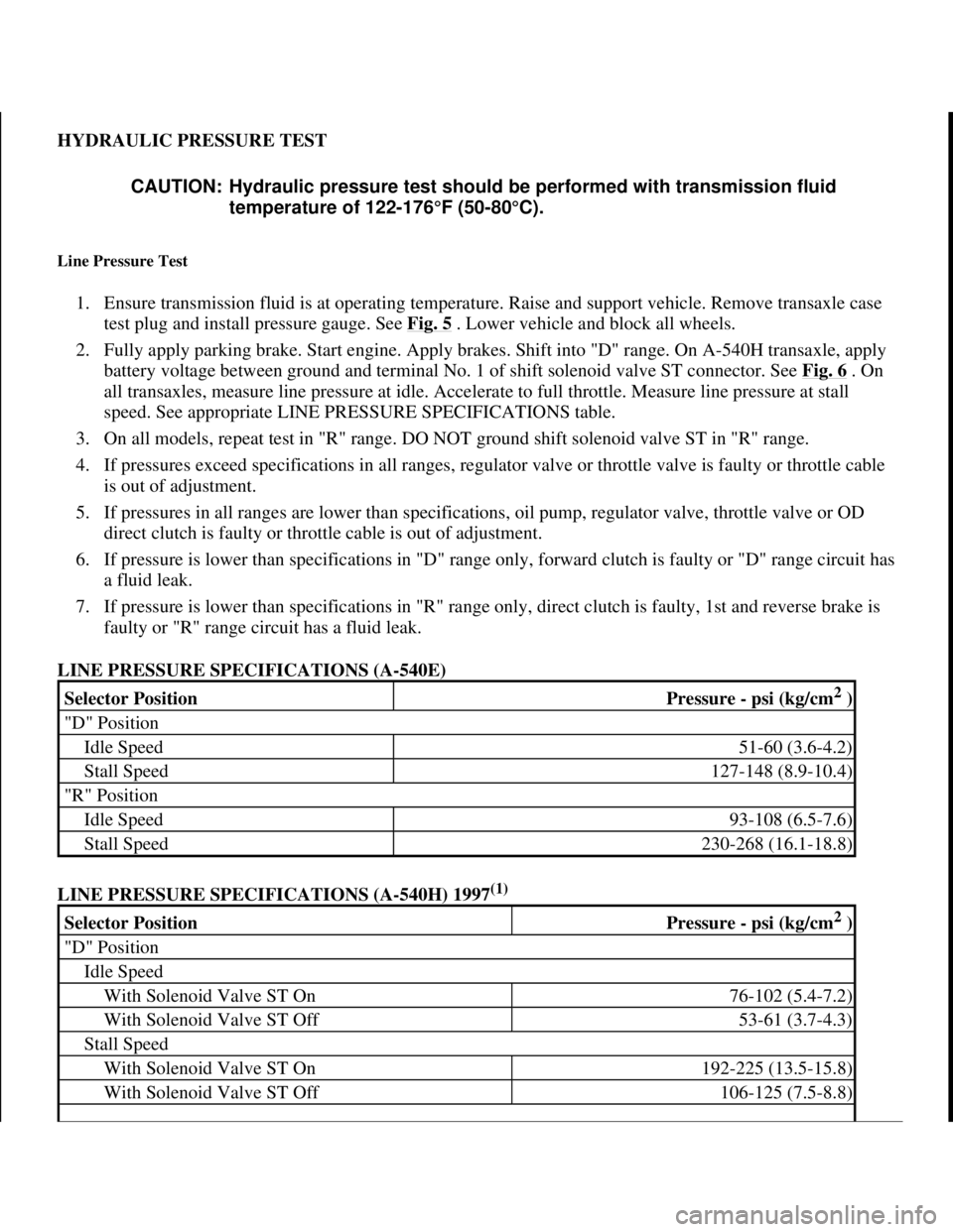
LINE PRESSURE SPECIFICATIONS (A-540E)
LINE PRESSURE SPECIFICATIONS (A-540H) 1997
(1)
CAUTION: Hydraulic pressure test should be performed with transmission fluid
temperature of 122-176°F (50-80°C).
Selector PositionPressure - psi (kg/cm2 )
"D" Position
Idle Speed51-60 (3.6-4.2)
Stall Speed127-148 (8.9-10.4)
"R" Position
Idle Speed93-108 (6.5-7.6)
Stall Speed230-268 (16.1-18.8)
Selector PositionPressure - psi (kg/cm2 )
"D" Position
Idle Speed
With Solenoid Valve ST On76-102 (5.4-7.2)
With Solenoid Valve ST Off53-61 (3.7-4.3)
Stall Speed
With Solenoid Valve ST On192-225 (13.5-15.8)
With Solenoid Valve ST Off106-125 (7.5-8.8)
1998 Toyota Avalon XLS
1997-99 AUTOMATIC TRANSMISSIONS Toyota A-540E, A-540H & A-541E Overhaul
Helpmelearn
November-03-08 10:28:17 AMPage 17 © 2005 Mitchell Repair Information Company, LLC.
Page 174 of 1632
TORQUE CONVERTER
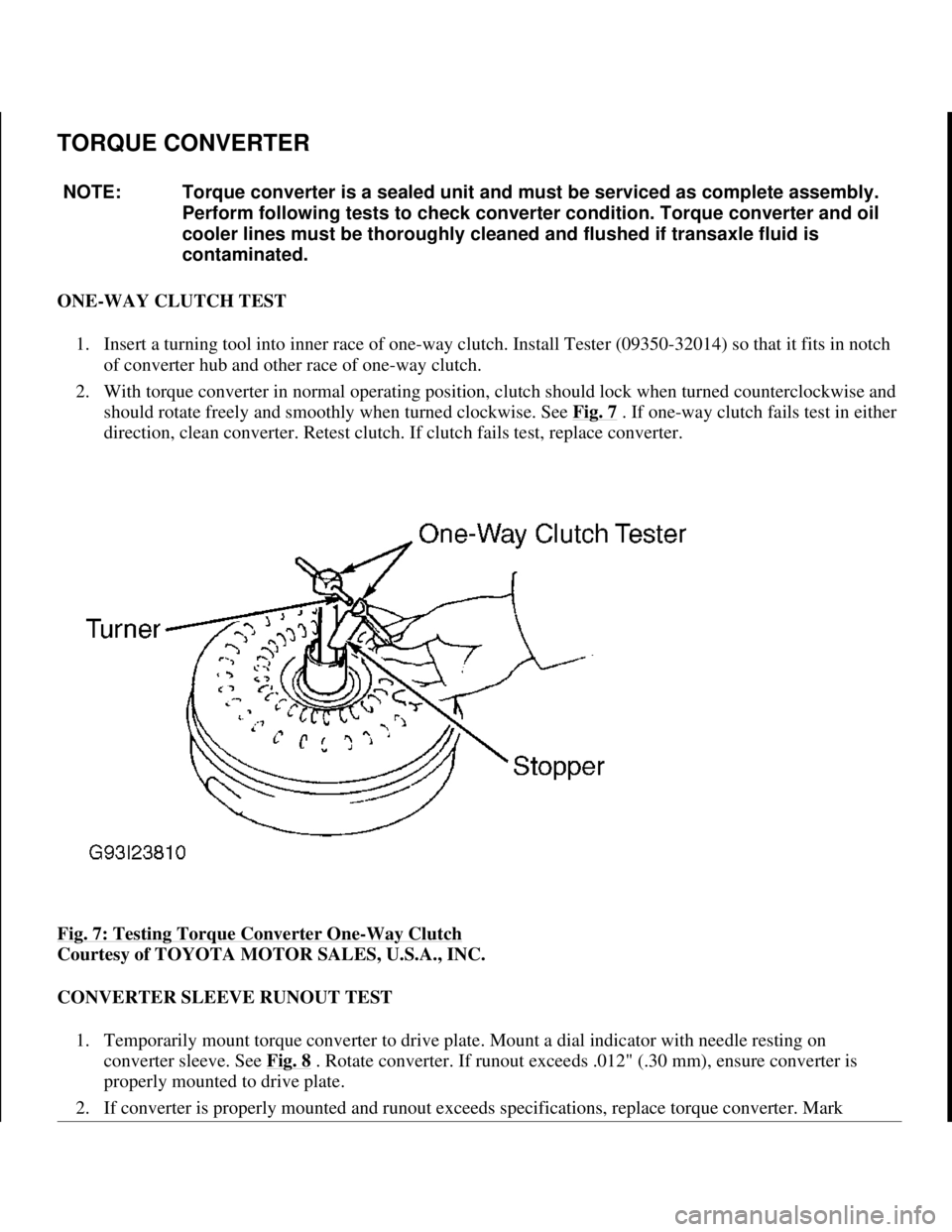
ONE-WAY CLUTCH TEST
1. Insert a turning tool into inner race of one-way clutch. Install Tester (09350-32014) so that it fits in notch
of converter hub and other race of one-way clutch.
2. With torque converter in normal operating position, clutch should lock when turned counterclockwise and
should rotate freely and smoothly when turned clockwise. See Fig. 7
. If one-way clutch fails test in either
direction, clean converter. Retest clutch. If clutch fails test, replace converter.
Fig. 7: Testing Torque Converter One
-Way Clutch
Courtesy of TOYOTA MOTOR SALES, U.S.A., INC.
CONVERTER SLEEVE RUNOUT TEST
1. Temporarily mount torque converter to drive plate. Mount a dial indicator with needle resting on
converter sleeve. See Fig. 8
. Rotate converter. If runout exceeds .012" (.30 mm), ensure converter is
properly mounted to drive plate.
2. If converter is properl
y mounted and runout exceeds specifications, replace torque converter. Mark NOTE: Torque converter is a sealed unit and must be serviced as complete assembly.
Perform following tests to check converter condition. Torque converter and oil
cooler lines must be thoroughly cleaned and flushed if transaxle fluid is
contaminated.
1998 Toyota Avalon XLS
1997-99 AUTOMATIC TRANSMISSIONS Toyota A-540E, A-540H & A-541E Overhaul
Helpmelearn
November-03-08 10:28:17 AMPage 20 © 2005 Mitchell Repair Information Company, LLC.