coil spring TOYOTA RAV4 1996 Service Repair Manual
[x] Cancel search | Manufacturer: TOYOTA, Model Year: 1996, Model line: RAV4, Model: TOYOTA RAV4 1996Pages: 1632, PDF Size: 41.64 MB
Page 203 of 1632
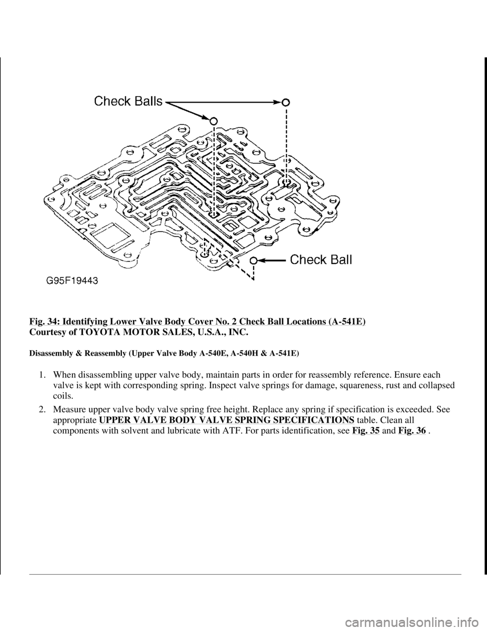
Fig. 34: Identifying Lower Valve Body Cover No. 2 Check Ball Locations (A-541E)
Courtesy of TOYOTA MOTOR SALES, U.S.A., INC.
Disassembly & Reassembly (Upper Valve Body A-540E, A-540H & A-541E)
1. When disassembling upper valve body, maintain parts in order for reassembly reference. Ensure each
valve is kept with corresponding spring. Inspect valve springs for damage, squareness, rust and collapsed
coils.
2. Measure upper valve body valve spring free height. Replace any spring if specification is exceeded. See
appropriate UPPER VALVE BODY VALVE SPRING SPECIFICATIONS
table. Clean all
components with solvent and lubricate with ATF. For parts identification, see Fig. 35
and Fig. 36.
1998 Toyota Avalon XLS
1997-99 AUTOMATIC TRANSMISSIONS Toyota A-540E, A-540H & A-541E Overhaul
Helpmelearn
November-03-08 10:28:18 AMPage 49 © 2005 Mitchell Repair Information Company, LLC.
Page 206 of 1632
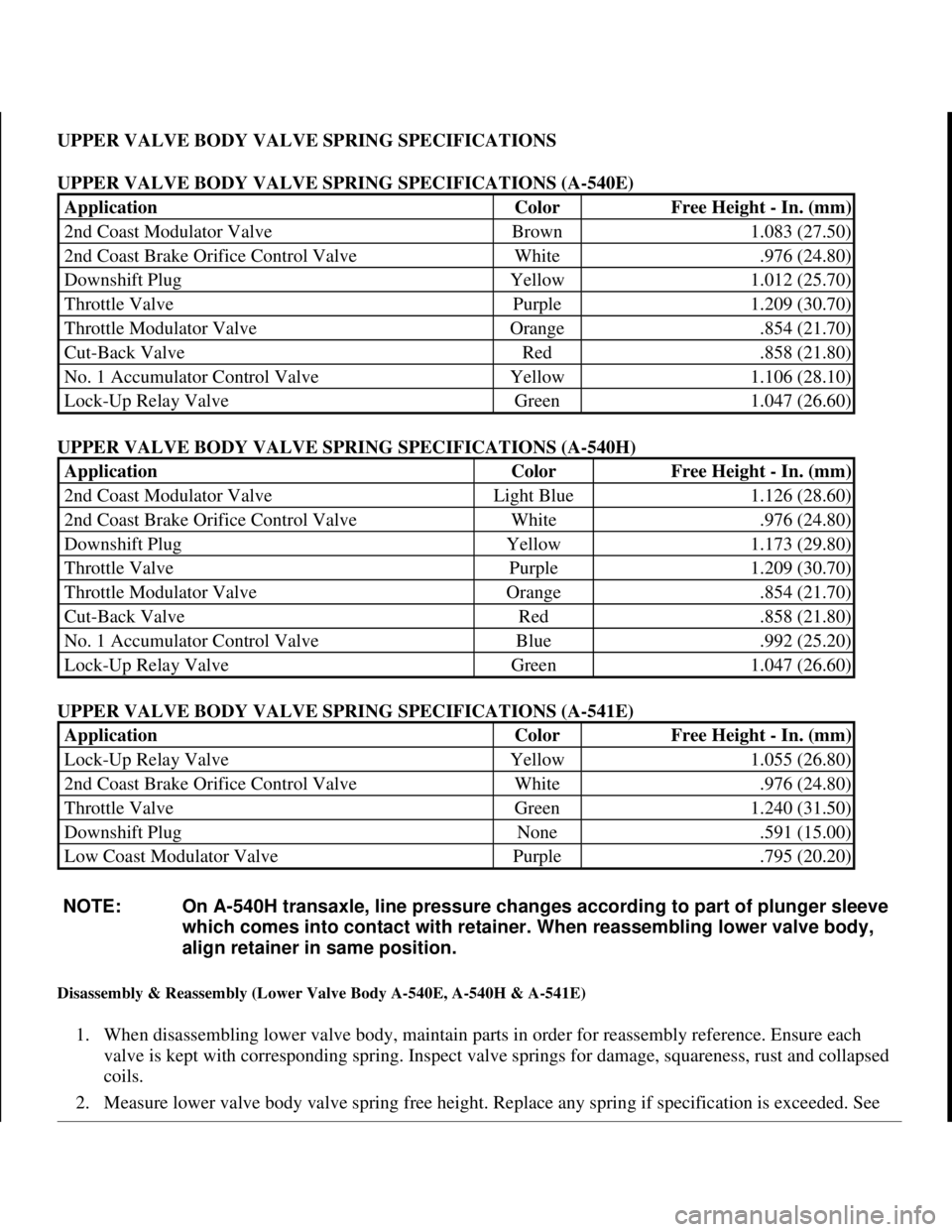
UPPER VALVE BODY VALVE SPRING SPECIFICATIONS
UPPER VALVE BODY VALVE SPRING SPECIFICATIONS (A-540E)
UPPER VALVE BODY VALVE SPRING SPECIFICATIONS (A-540H)
UPPER VALVE BODY VALVE SPRING SPECIFICATIONS (A-541E)
Disassembly & Reassembly (Lower Valve Body A-540E, A-540H & A-541E)
1. When disassembling lower valve body, maintain parts in order for reassembly reference. Ensure each
valve is kept with corresponding spring. Inspect valve springs for damage, squareness, rust and collapsed
coils.
2. Measure lower valve bod
y valve spring free height. Replace any spring if specification is exceeded. See
ApplicationColorFree Height - In. (mm)
2nd Coast Modulator ValveBrown1.083 (27.50)
2nd Coast Brake Orifice Control ValveWhite.976 (24.80)
Downshift PlugYellow1.012 (25.70)
Throttle ValvePurple1.209 (30.70)
Throttle Modulator ValveOrange.854 (21.70)
Cut-Back ValveRed.858 (21.80)
No. 1 Accumulator Control ValveYellow1.106 (28.10)
Lock-Up Relay ValveGreen1.047 (26.60)
ApplicationColorFree Height - In. (mm)
2nd Coast Modulator ValveLight Blue1.126 (28.60)
2nd Coast Brake Orifice Control ValveWhite.976 (24.80)
Downshift PlugYellow1.173 (29.80)
Throttle ValvePurple1.209 (30.70)
Throttle Modulator ValveOrange.854 (21.70)
Cut-Back ValveRed.858 (21.80)
No. 1 Accumulator Control ValveBlue.992 (25.20)
Lock-Up Relay ValveGreen1.047 (26.60)
ApplicationColorFree Height - In. (mm)
Lock-Up Relay ValveYellow1.055 (26.80)
2nd Coast Brake Orifice Control ValveWhite.976 (24.80)
Throttle ValveGreen1.240 (31.50)
Downshift PlugNone.591 (15.00)
Low Coast Modulator ValvePurple.795 (20.20)
NOTE: On A-540H transaxle, line pressure changes according to part of plunger sleeve
which comes into contact with retainer. When reassembling lower valve body,
align retainer in same position.
1998 Toyota Avalon XLS
1997-99 AUTOMATIC TRANSMISSIONS Toyota A-540E, A-540H & A-541E Overhaul
Helpmelearn
November-03-08 10:28:18 AMPage 52 © 2005 Mitchell Repair Information Company, LLC.
Page 701 of 1632

Removal
1. Release fuel pressure. See FUEL PRESSURE RELEASE . Drain cooling system. Raise and support
vehicle. Remove right lower engine cover.
2. Disconnect control cables at throttle body. Remove air cleaner assembly and air cleaner case. Remove
accessory drive belt and generator.
3. Remove front exhaust pipe. Remove exhaust manifold and heat insulator assembly. Disconnect oxygen
sensor (except California) or Air/Fuel (A/F) ratio sensor (California), and remove exhaust manifold and
heat shield. Remove sensors from exhaust manifold and front catalytic converter, if equipped.
4. Remove heat insulator from front exhaust pipe. Remove throttle body and gasket. Remove ignition coils
with spark plug wires attached.
5. Disconnect necessary electrical connectors, coolant hoses and vacuum hoses from cylinder head and
intake manifold. Remove coolant outlet, coolant by-pass pipe and gaskets.
6. Disconnect hoses and ground strap. Remove union bolt, and disconnect fuel line at fuel filter. Remove
EGR valve and vacuum modulator. Disconnect power steering idle-up hoses from air tube.
7. Remove 2 bolts and accelerator cable bracket. Disconnect PCV hoses, cable brackets and control cables
for access to valve cover. Disconnect engine wiring harness protector at rear of timing belt cover for
access to valve cover. Remove nuts, grommets, valve cover and gasket. Note location of grommets for
reassembly reference, as grommets must be installed in original location.
8. Remove bolts, and disconnect engine wiring harness protector from left side of intake manifold.
Disconnect electrical connectors at injectors, A/C compressor and crankshaft position sensor. Remove
engine wiring harness clamps from timing belt cover and generator drive belt adjusting bar.
9. Remove scuff plate from passenger-side door opening and passenger-side kick panel. Remove right side
cowl side trim and floor carpet center cover. Disconnect 2 electrical connectors from Engine Control
Module (ECM), and 2 electrical connectors on bracket. See Fig. 9
. Disconnect electrical connector for
relay box located behind passenger-side kick panel.
10. Disconnect engine wiring harness clamp located on engine wiring, near firewall. Pull engine wiring
harness out through firewall. Remove engine wiring harness from between cylinder head and intake
manifold.
11. Disconnect timing belt from camshaft timing pulley. Remove camshaft timing pulley. Remove No. 1 idler
pulley and tension spring. See TIMING BELT
. Remove 3 bolts and timing belt cover. See Fig. 14 .
After removing timing belt from camshaft sprocket, support timing belt so belt does not come off
crankshaft sprocket.
1999 Toyota RAV4
1999-2000 ENGINES 2.0L 4-Cylinder
Microsoft
Sunday, November 22, 2009 10:22:26 AMPage 18 © 2005 Mitchell Repair Information Company, LLC.
Page 826 of 1632
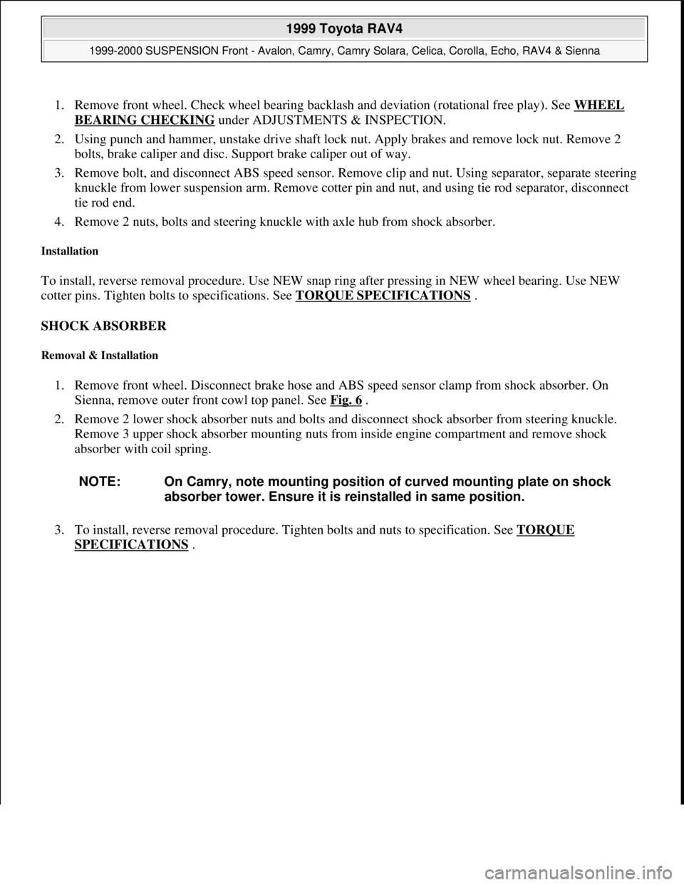
1. Remove front wheel. Check wheel bearing backlash and deviation (rotational free play). See WHEEL
BEARING CHECKING under ADJUSTMENTS & INSPECTION.
2. Using punch and hammer, unstake drive shaft lock nut. Apply brakes and remove lock nut. Remove 2
bolts, brake caliper and disc. Support brake caliper out of way.
3. Remove bolt, and disconnect ABS speed sensor. Remove clip and nut. Using separator, separate steering
knuckle from lower suspension arm. Remove cotter pin and nut, and using tie rod separator, disconnect
tie rod end.
4. Remove 2 nuts, bolts and steering knuckle with axle hub from shock absorber.
Installation
To install, reverse removal procedure. Use NEW snap ring after pressing in NEW wheel bearing. Use NEW
cotter pins. Tighten bolts to specifications. See TORQUE SPECIFICATIONS
.
SHOCK ABSORBER
Removal & Installation
1. Remove front wheel. Disconnect brake hose and ABS speed sensor clamp from shock absorber. On
Sienna, remove outer front cowl top panel. See Fig. 6
.
2. Remove 2 lower shock absorber nuts and bolts and disconnect shock absorber from steering knuckle.
Remove 3 upper shock absorber mounting nuts from inside engine compartment and remove shock
absorber with coil spring.
3. To install, reverse removal procedure. Tighten bolts and nuts to specification. See TORQUE
SPECIFICATIONS . NOTE: On Camry, note mounting position of curved mounting plate on shock
absorber tower. Ensure it is reinstalled in same position.
1999 Toyota RAV4
1999-2000 SUSPENSION Front - Avalon, Camry, Camry Solara, Celica, Corolla, Echo, RAV4 & Sienna
Microsoft
Sunday, November 22, 2009 10:36:34 AMPage 8 © 2005 Mitchell Repair Information Company, LLC.
Page 1139 of 1632
1999-2000 SUSPENSION
Rear - Front Wheel Drive
DESCRIPTION
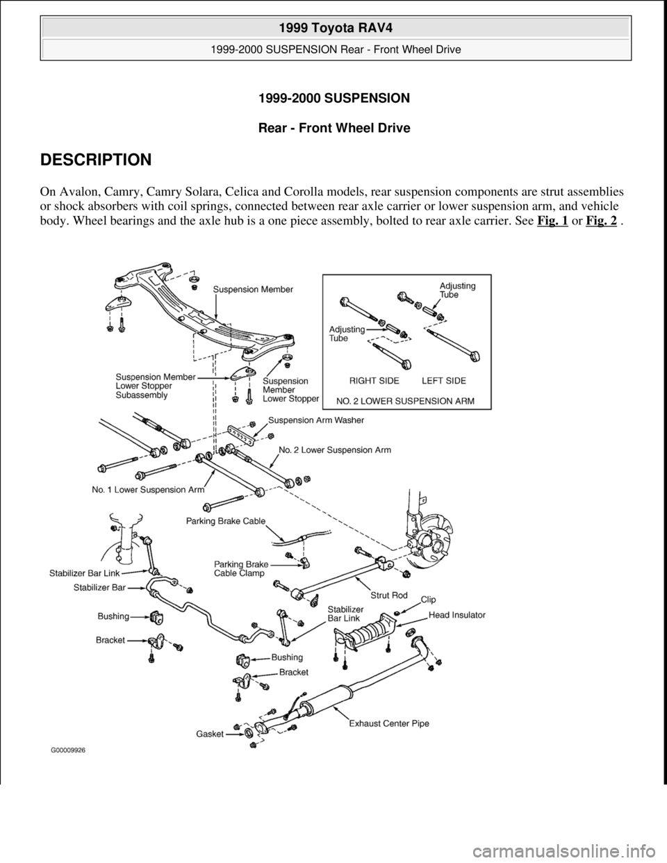
On Avalon, Camry, Camry Solara, Celica and Corolla models, rear suspension components are strut assemblies
or shock absorbers with coil springs, connected between rear axle carrier or lower suspension arm, and vehicle
body. Wheel bearings and the axle hub is a one piece assembly, bolted to rear axle carrier. See Fig. 1
or Fig. 2 .
1999 Toyota RAV4
1999-2000 SUSPENSION Rear - Front Wheel Drive
1999 Toyota RAV4
1999-2000 SUSPENSION Rear - Front Wheel Drive
Microsoft
Sunday, November 22, 2009 10:37:21 AMPage 1 © 2005 Mitchell Repair Information Company, LLC.
Microsoft
Sunday, November 22, 2009 10:37:26 AMPage 1 © 2005 Mitchell Repair Information Company, LLC.
Page 1141 of 1632
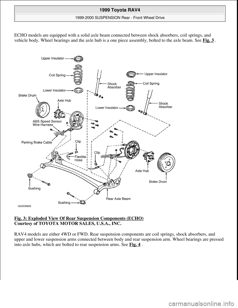
ECHO models are equipped with a solid axle beam connected between shock absorbers, coil springs, and
vehicle body. Wheel bearings and the axle hub is a one piece assembly, bolted to the axle beam. See Fig. 3
.
Fig. 3: Exploded View Of Rear Suspension Components (ECHO)
Courtesy of TOYOTA MOTOR SALES, U.S.A., INC.
RAV4 models are either 4WD or FWD. Rear suspension components are coil springs, shock absorbers, and
upper and lower suspension arms connected between body and rear suspension arm. Wheel bearings are pressed
into axle hubs, which are bolted to rear suspension arms. See Fig. 4
.
1999 Toyota RAV4
1999-2000 SUSPENSION Rear - Front Wheel Drive
Microsoft
Sunday, November 22, 2009 10:37:21 AMPage 3 © 2005 Mitchell Repair Information Company, LLC.
Page 1143 of 1632
WHEEL BEARING INSPECTION
Raise and support vehicle. Remove wheel and brake drum, or rotor (if equipped). Position dial indicator with
stem against center of axle hub. Move axle hub in and out while observing dial indicator. Replace hub if axial
play exceeds .002" (.05 mm). Measure hub axial runout. Replace hub if runout exceeds .0028" (.07 mm).
WHEEL BEARING ADJUSTMENT
Hubs must be replaced if axle end play or runout are not within specification. No adjustment is available. See
WHEEL BEARINGS (HUBS)
under REMOVAL & INSTALLATION
REMOVAL & INSTALLATION
AXLE BEAM
Removal (ECHO)
1. Raise and support vehicle. Remove rear wheels and brake drums. Disconnect brakelines from flex hoses,
remove retaining clips from shock absorbers and plug openings. Disconnect ABS sensor and remove
harness clamp from axle beam. Disconnect parking brake cable from backing plate and remove cable
clamp from axle beam. Remove axle hub assemblies. Remove backing plate assemblies, with brake shoes
still attached.
2. Remove high-mounted stop light from rear package tray. Remove 2 clips and remove package tray.
Remove rear seat. Remove door scuff plate and door opening trim. See Fig. 5
. Remove rear seat outer
seat belts and remove quarter trim panels. On 2 door models, remove outer anchor for front seat shoulder
belt and remove roof side inner garnish. On all models, remove room partition board.
3. Using 2 floor jacks, support rear axle beam under each coil spring. While holding shock absorber shaft,
remove the 2 upper nuts, disconnecting lower suspension supports from body. Lower jacks slowly.
Remove coil springs and insulators. Remove axle beam-to-
body bolts. Remove axle beam. NOTE: See SPECIFICATIONS & PROCEDURES
in WHEEL ALIGNMENT article.
1999 Toyota RAV4
1999-2000 SUSPENSION Rear - Front Wheel Drive
Microsoft
Sunday, November 22, 2009 10:37:21 AMPage 5 © 2005 Mitchell Repair Information Company, LLC.
Page 1144 of 1632
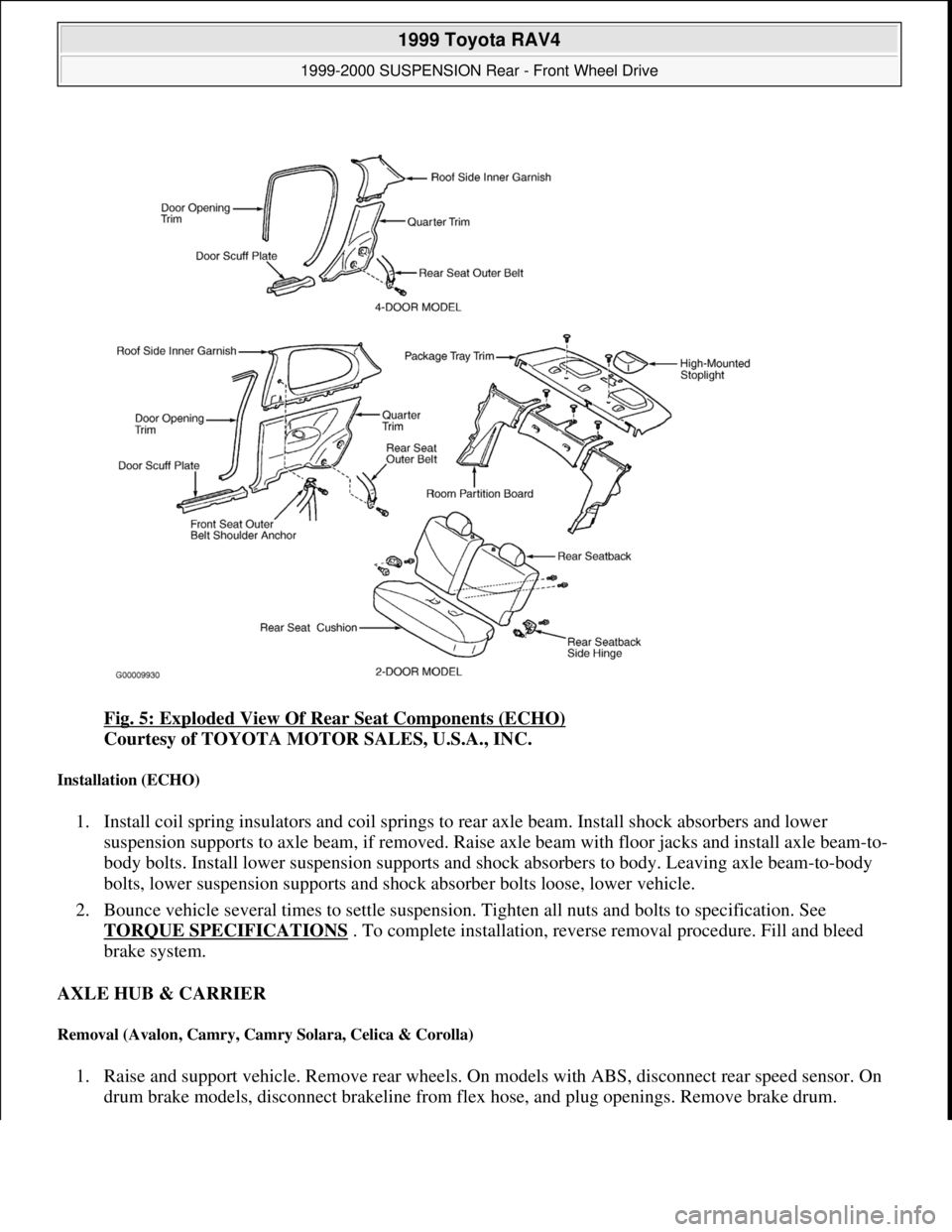
Fig. 5: Exploded View Of Rear Seat Components (ECHO)
Courtesy of TOYOTA MOTOR SALES, U.S.A., INC.
Installation (ECHO)
1. Install coil spring insulators and coil springs to rear axle beam. Install shock absorbers and lower
suspension supports to axle beam, if removed. Raise axle beam with floor jacks and install axle beam-to-
body bolts. Install lower suspension supports and shock absorbers to body. Leaving axle beam-to-body
bolts, lower suspension supports and shock absorber bolts loose, lower vehicle.
2. Bounce vehicle several times to settle suspension. Tighten all nuts and bolts to specification. See
TORQUE SPECIFICATIONS
. To complete installation, reverse removal procedure. Fill and bleed
brake system.
AXLE HUB & CARRIER
Removal (Avalon, Camry, Camry Solara, Celica & Corolla)
1. Raise and support vehicle. Remove rear wheels. On models with ABS, disconnect rear speed sensor. On
drum brake models, disconnect brakeline from flex hose, and plu
g openings. Remove brake drum.
1999 Toyota RAV4
1999-2000 SUSPENSION Rear - Front Wheel Drive
Microsoft
Sunday, November 22, 2009 10:37:21 AMPage 6 © 2005 Mitchell Repair Information Company, LLC.
Page 1145 of 1632
2. On disc brake models, remove rotor and caliper. Leaving flex hose attached, suspend caliper aside. On all
models, remove 4 axle hub-to-axle carrier bolts, axle hub and "O" ring.
3. Note position of nuts on suspension arms and strut rods for installation reference. Disconnect strut rod
from axle carrier. Disconnect No. 1 and No. 2 lower suspension arms from axle carrier. Remove 2 bolts
and nuts, and remove axle carrier.
Installation (Avalon, Camry, Camry Solara, Celica & Corolla)
To install, reverse removal procedure. Coat NEW "O" ring with grease and install hub. Tighten all fasteners to
specification. See TORQUE SPECIFICATIONS
. Bleed brake system. Check rear wheel alignment.
Removal (RAV4)
1. Raise and support vehicle. Remove rear wheel and brake drum. On 4WD models, remove drive axle.
Remove ABS speed sensor (if equipped). Remove drive axle lock nut. Place matchmarks on drive axle
and differential gear shaft. Remove the 4 nuts and remove drive axle from differential side gear. On FWD
models, disconnect ABS sensor and remove harness clamp (if equipped). On all models, remove 2
brakeline clamps from rear No. 1 suspension arm. Remove parking brake cable clamp. See Fig. 4
.
2. Remove 4 bolts and remove axle hub and backing plate, leaving brake shoes attached. Disconnect lower
end of shock absorber. Using Ball Joint Puller (09628-62011), disconnect upper and lower suspension
arms from rear No. 1 suspension arm. Place matchmarks on camber adjusting cam and suspension
member and remove bolt. See Fig. 6
. Place matchmarks on toe adjusting cam and body and loosen bolt.
See Fig. 7
. Remove coil spring and upper insulator. Remove loosened toe adjusting cam bolt. Remove
rear No. 1 suspension arm. NOTE: Bounce vehicle several times to stabilize suspension. Tighten axle carrier-to-
shock absorber assembly and suspension arm bolts to specification with
vehicle at normal operating height.
1999 Toyota RAV4
1999-2000 SUSPENSION Rear - Front Wheel Drive
Microsoft
Sunday, November 22, 2009 10:37:21 AMPage 7 © 2005 Mitchell Repair Information Company, LLC.
Page 1168 of 1632
1.Pull-In Coil Test
Disconnect field coil lead from terminal "C". Connect jumper wires from negative battery terminal to
terminal "C" and to starter housing. When wire is connected from positive battery terminal to terminal
No. 50, clutch pinion gear should extend fully. See Fig. 10
or Fig. 13 . If clutch pinion gear does not
move, replace solenoid. If clutch pinion gear does move, go to next test.
2.Hold-In Coil Test
With battery connected as in previous test and clutch pinion gear still extended, disconnect jumper wire
from starter terminal "C". See Fig. 11
or Fig. 14 . Clutch pinion gear should remain extended. If clutch
pinion gear does not remain extended, replace solenoid. If clutch pinion gear does remain extended, go to
next test.
3.Drive Pinion Return Test
Disconnect jumper wire from negative battery terminal to starter housing. See Fig. 12
or Fig. 15 . Pinion
gear should now retract. If it does not retract, replace solenoid.
STARTER COMPONENT INSPECTION
Armature Coil
1. Using ohmmeter, check for continuity between armature coil core and insulation between commutator
segments. If continuity is present, replace armature. Check armature for shorts using a growler. Replace
armature as necessary.
2. Check for continuity between segments of commutator. If continuity is not present between any segment,
replace armature.
Brushes & Springs
1. Check brush length. If length is less than specification, replace brushes. See STARTER
SPECIFICATIONS . If brushes are okay, go to next step.
2. Check brush holders, springs, spring clip and insulation between positive and negative holders. Verify no
continuity exists between positive and negative brush holders. Repair or replace components as needed.
Clutch Assembly & Gears
1. Inspect teeth on pinion gear, idler gear and clutch assembly for wear or damage. If damaged, replace gear
or clutch assembly and inspect flywheel ring gear for wear or damage.
2. Inspect clutch pinion gear by rotating pinion gear. Depending on engine, pinion gear will rotate freely in
one direction and lock when rotated in opposite direction. On Avalon, Camry, Camry Solara, Celica,
RAV4 and Sienna, clutch pinion
gear will lock when rotated in a clockwise direction. On all other CAUTION: DO NOT engage starter solenoid for more than 5 seconds during testing,
or damage to coil winding will result.
1999 Toyota RAV4
1999-2000 STARTING & CHARGING SYSTEMS Starters
Microsoft
Sunday, November 22, 2009 10:19:18 AMPage 13 © 2005 Mitchell Repair Information Company, LLC.