oil temperature TOYOTA RAV4 1996 Service Repair Manual
[x] Cancel search | Manufacturer: TOYOTA, Model Year: 1996, Model line: RAV4, Model: TOYOTA RAV4 1996Pages: 1632, PDF Size: 41.64 MB
Page 171 of 1632
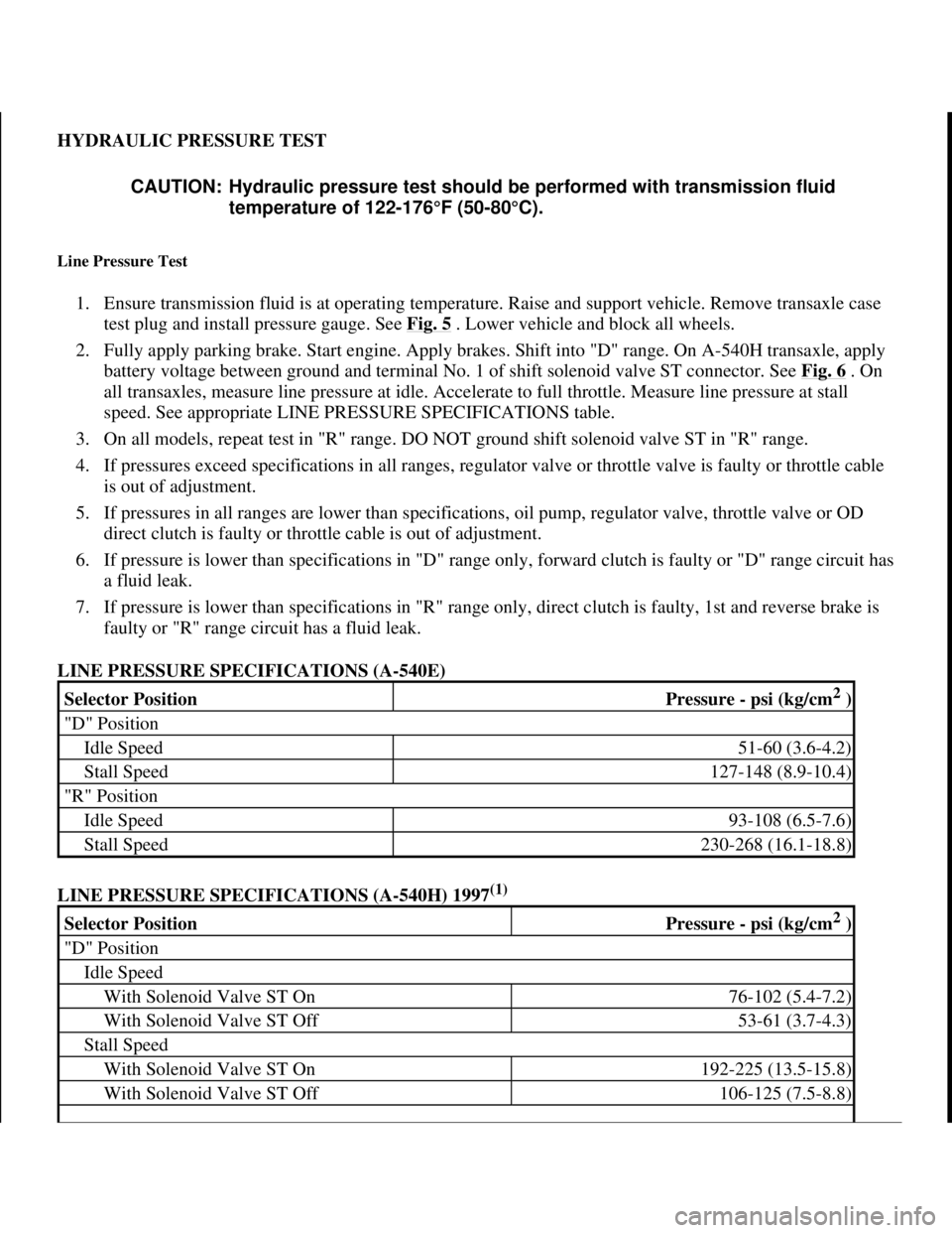
HYDRAULIC PRESSURE TEST
Line Pressure Test
1. Ensure transmission fluid is at operating temperature. Raise and support vehicle. Remove transaxle case
test plug and install pressure gauge. See Fig. 5
. Lower vehicle and block all wheels.
2. Fully apply parking brake. Start engine. Apply brakes. Shift into "D" range. On A-540H transaxle, apply
battery voltage between ground and terminal No. 1 of shift solenoid valve ST connector. See Fig. 6
. On
all transaxles, measure line pressure at idle. Accelerate to full throttle. Measure line pressure at stall
speed. See appropriate LINE PRESSURE SPECIFICATIONS table.
3. On all models, repeat test in "R" range. DO NOT ground shift solenoid valve ST in "R" range.
4. If pressures exceed specifications in all ranges, regulator valve or throttle valve is faulty or throttle cable
is out of adjustment.
5. If pressures in all ranges are lower than specifications, oil pump, regulator valve, throttle valve or OD
direct clutch is faulty or throttle cable is out of adjustment.
6. If pressure is lower than specifications in "D" range only, forward clutch is faulty or "D" range circuit has
a fluid leak.
7. If pressure is lower than specifications in "R" range only, direct clutch is faulty, 1st and reverse brake is
faulty or "R" range circuit has a fluid leak.
LINE PRESSURE SPECIFICATIONS (A-540E)
LINE PRESSURE SPECIFICATIONS (A-540H) 1997
(1)
CAUTION: Hydraulic pressure test should be performed with transmission fluid
temperature of 122-176°F (50-80°C).
Selector PositionPressure - psi (kg/cm2 )
"D" Position
Idle Speed51-60 (3.6-4.2)
Stall Speed127-148 (8.9-10.4)
"R" Position
Idle Speed93-108 (6.5-7.6)
Stall Speed230-268 (16.1-18.8)
Selector PositionPressure - psi (kg/cm2 )
"D" Position
Idle Speed
With Solenoid Valve ST On76-102 (5.4-7.2)
With Solenoid Valve ST Off53-61 (3.7-4.3)
Stall Speed
With Solenoid Valve ST On192-225 (13.5-15.8)
With Solenoid Valve ST Off106-125 (7.5-8.8)
1998 Toyota Avalon XLS
1997-99 AUTOMATIC TRANSMISSIONS Toyota A-540E, A-540H & A-541E Overhaul
Helpmelearn
November-03-08 10:28:17 AMPage 17 © 2005 Mitchell Repair Information Company, LLC.
Page 235 of 1632
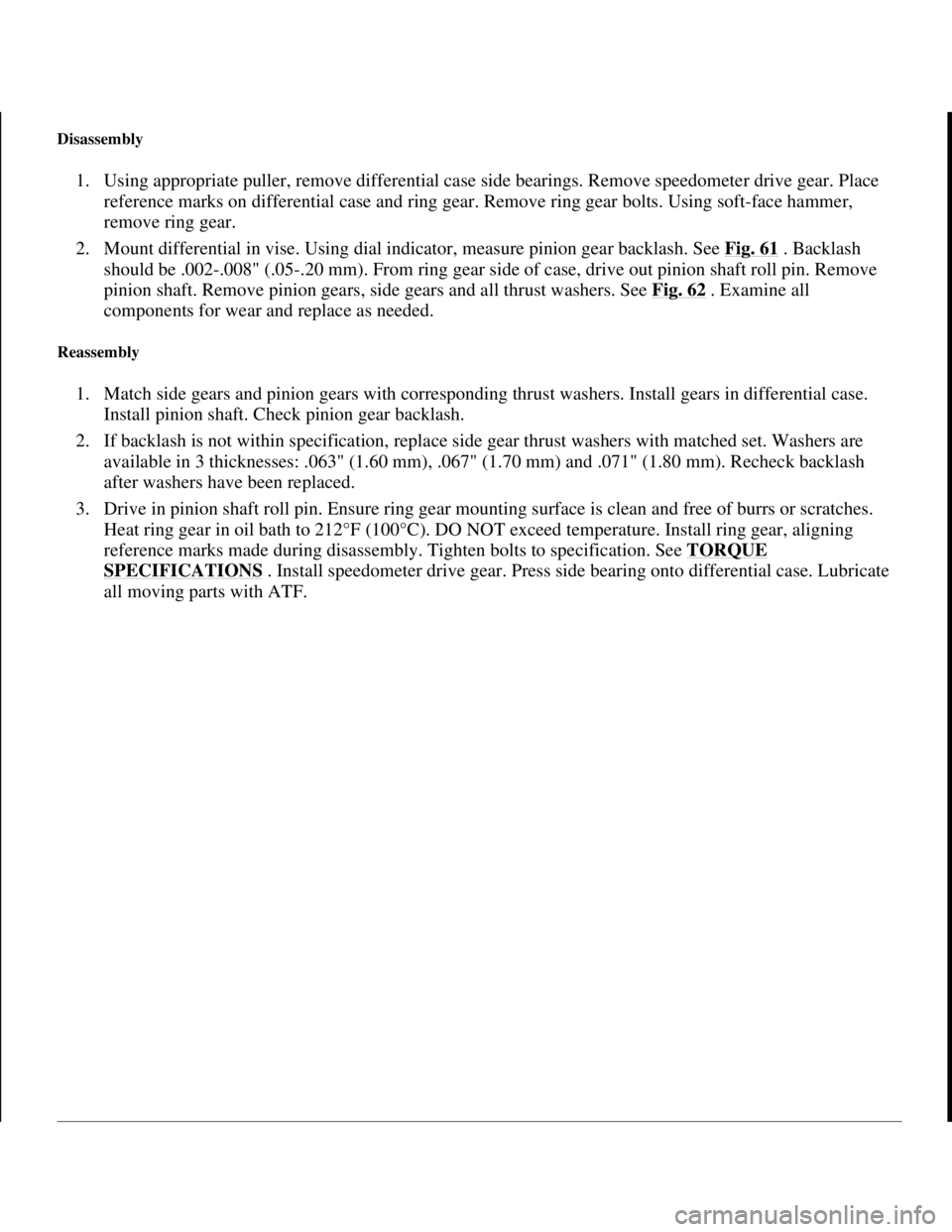
Disassembly
1. Using appropriate puller, remove differential case side bearings. Remove speedometer drive gear. Place
reference marks on differential case and ring gear. Remove ring gear bolts. Using soft-face hammer,
remove ring gear.
2. Mount differential in vise. Using dial indicator, measure pinion gear backlash. See Fig. 61
. Backlash
should be .002-.008" (.05-.20 mm). From ring gear side of case, drive out pinion shaft roll pin. Remove
pinion shaft. Remove pinion gears, side gears and all thrust washers. See Fig. 62
. Examine all
components for wear and replace as needed.
Reassembly
1. Match side gears and pinion gears with corresponding thrust washers. Install gears in differential case.
Install pinion shaft. Check pinion gear backlash.
2. If backlash is not within specification, replace side gear thrust washers with matched set. Washers are
available in 3 thicknesses: .063" (1.60 mm), .067" (1.70 mm) and .071" (1.80 mm). Recheck backlash
after washers have been replaced.
3. Drive in pinion shaft roll pin. Ensure ring gear mounting surface is clean and free of burrs or scratches.
Heat ring gear in oil bath to 212°F (100°C). DO NOT exceed temperature. Install ring gear, aligning
reference marks made during disassembly. Tighten bolts to specification. See TORQUE
SPECIFICATIONS . Install speedometer drive gear. Press side bearing onto differential case. Lubricate
all moving parts with ATF.
1998 Toyota Avalon XLS
1997-99 AUTOMATIC TRANSMISSIONS Toyota A-540E, A-540H & A-541E Overhaul
Helpmelearn
November-03-08 10:28:19 AMPage 81 © 2005 Mitchell Repair Information Company, LLC.
Page 266 of 1632
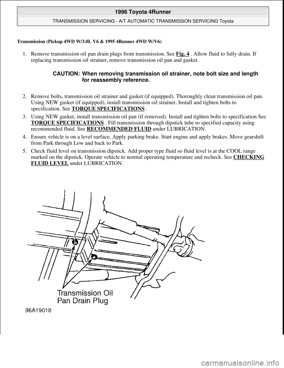
Transmission (Pickup 4WD W/3.0L V6 & 1995 4Runner 4WD W/V6)
1. Remove transmission oil pan drain plugs from transmission. See Fig. 4 . Allow fluid to fully drain. If
replacing transmission oil strainer, remove transmission oil pan and gasket.
2. Remove bolts, transmission oil strainer and gasket (if equipped). Thoroughly clean transmission oil pan.
Using NEW gasket (if equipped), install transmission oil strainer. Install and tighten bolts to
specification. See TORQUE SPECIFICATIONS
.
3. Using NEW gasket, install transmission oil pan (if removed). Install and tighten bolts to specification See
TORQUE SPECIFICATIONS
. Fill transmission through dipstick tube to specified capacity using
recommended fluid. See RECOMMENDED FLUID
under LUBRICATION.
4. Ensure vehicle is on a level surface. Apply parking brake. Start engine and apply brakes. Move gearshift
from Park through Low and back to Park.
5. Check fluid level on transmission dipstick. Add proper type fluid so fluid level is at the COOL range
marked on the dipstick. Operate vehicle to normal operating temperature and recheck. See CHECKING
FLUID LEVEL under LUBRICATION. CAUTION: When removing transmission oil strainer, note bolt size and length
for reassembly reference.
1996 Toyota 4Runner
TRANSMISSION SERVICING - A/T AUTOMATIC TRANSMISSION SERVICING Toyota
Microsoft
Tuesday, August 18, 2009 7:18:46 PMPage 10 © 2005 Mitchell Repair Information Company, LLC.
Page 267 of 1632
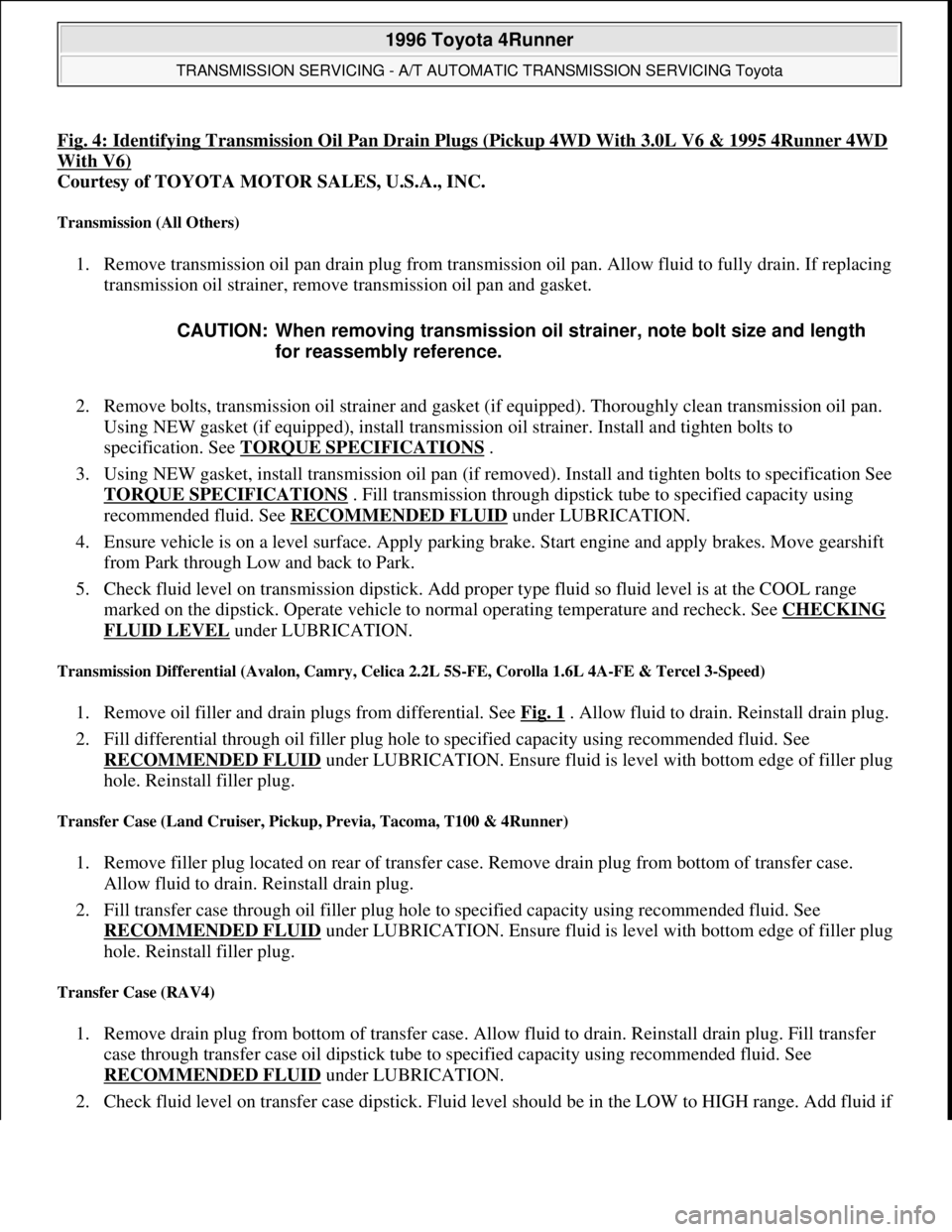
Fig. 4: Identifying Transmission Oil Pan Drain Plugs (Pickup 4WD With 3.0L V6 & 1995 4Runner 4WD
With V6)
Courtesy of TOYOTA MOTOR SALES, U.S.A., INC.
Transmission (All Others)
1. Remove transmission oil pan drain plug from transmission oil pan. Allow fluid to fully drain. If replacing
transmission oil strainer, remove transmission oil pan and gasket.
2. Remove bolts, transmission oil strainer and gasket (if equipped). Thoroughly clean transmission oil pan.
Using NEW gasket (if equipped), install transmission oil strainer. Install and tighten bolts to
specification. See TORQUE SPECIFICATIONS
.
3. Using NEW gasket, install transmission oil pan (if removed). Install and tighten bolts to specification See
TORQUE SPECIFICATIONS
. Fill transmission through dipstick tube to specified capacity using
recommended fluid. See RECOMMENDED FLUID
under LUBRICATION.
4. Ensure vehicle is on a level surface. Apply parking brake. Start engine and apply brakes. Move gearshift
from Park through Low and back to Park.
5. Check fluid level on transmission dipstick. Add proper type fluid so fluid level is at the COOL range
marked on the dipstick. Operate vehicle to normal operating temperature and recheck. See CHECKING
FLUID LEVEL under LUBRICATION.
Transmission Differential (Avalon, Camry, Celica 2.2L 5S-FE, Corolla 1.6L 4A-FE & Tercel 3-Speed)
1. Remove oil filler and drain plugs from differential. See Fig. 1 . Allow fluid to drain. Reinstall drain plug.
2. Fill differential through oil filler plug hole to specified capacity using recommended fluid. See
RECOMMENDED FLUID
under LUBRICATION. Ensure fluid is level with bottom edge of filler plug
hole. Reinstall filler plug.
Transfer Case (Land Cruiser, Pickup, Previa, Tacoma, T100 & 4Runner)
1. Remove filler plug located on rear of transfer case. Remove drain plug from bottom of transfer case.
Allow fluid to drain. Reinstall drain plug.
2. Fill transfer case through oil filler plug hole to specified capacity using recommended fluid. See
RECOMMENDED FLUID
under LUBRICATION. Ensure fluid is level with bottom edge of filler plug
hole. Reinstall filler plug.
Transfer Case (RAV4)
1. Remove drain plug from bottom of transfer case. Allow fluid to drain. Reinstall drain plug. Fill transfer
case through transfer case oil dipstick tube to specified capacity using recommended fluid. See
RECOMMENDED FLUID
under LUBRICATION.
2. Check fluid level on transfer case dipstick. Fluid level should be in the LOW to HIGH range. Add fluid if CAUTION: When removing transmission oil strainer, note bolt size and length
for reassembly reference.
1996 Toyota 4Runner
TRANSMISSION SERVICING - A/T AUTOMATIC TRANSMISSION SERVICING Toyota
Microsoft
Tuesday, August 18, 2009 7:18:46 PMPage 11 © 2005 Mitchell Repair Information Company, LLC.
Page 606 of 1632
1999-2000 DRIVE AXLES
Differentials, Axle Shafts & Drive Shafts -- Rear Integral Housing -- RAV4
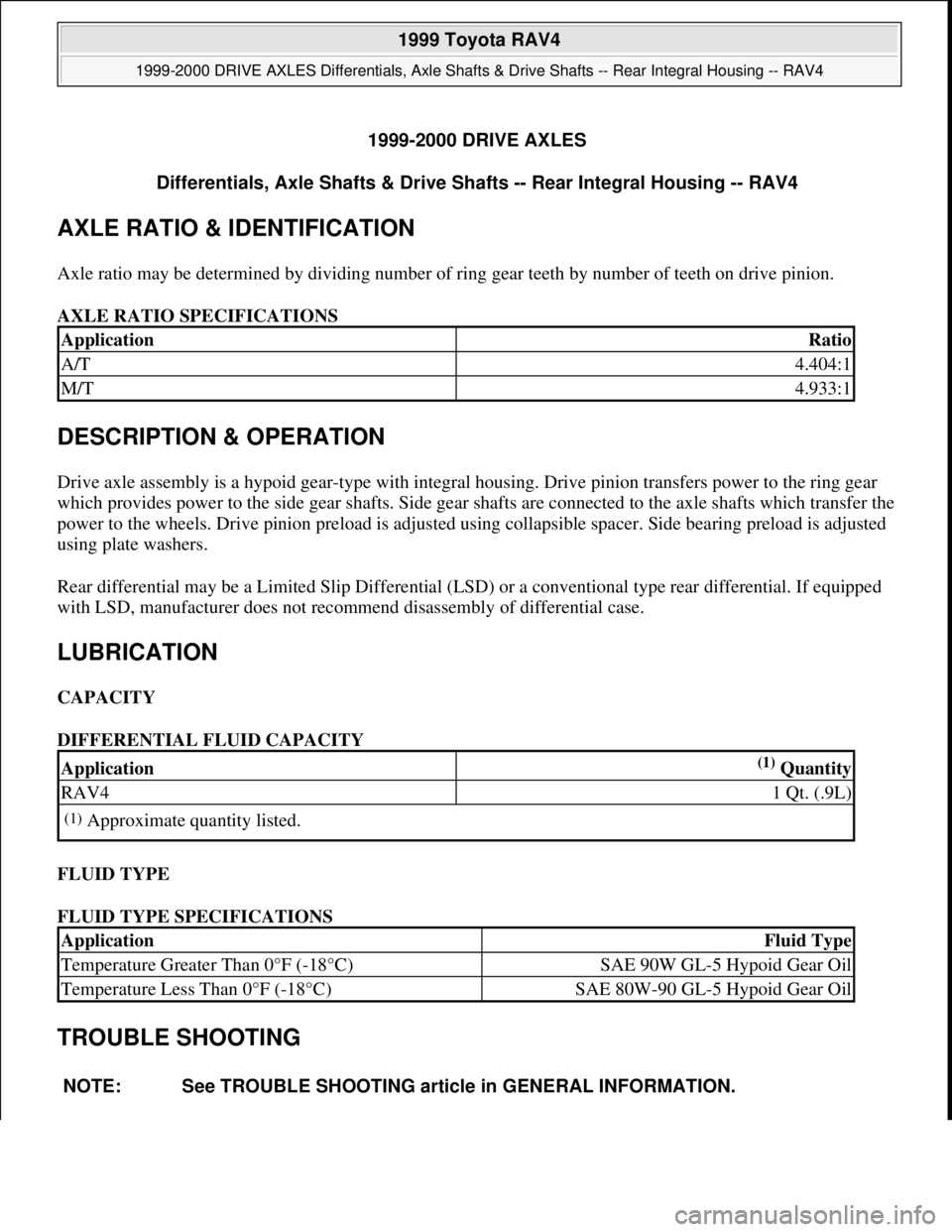
AXLE RATIO & IDENTIFICATION
Axle ratio may be determined by dividing number of ring gear teeth by number of teeth on drive pinion.
AXLE RATIO SPECIFICATIONS
DESCRIPTION & OPERATION
Drive axle assembly is a hypoid gear-type with integral housing. Drive pinion transfers power to the ring gear
which provides power to the side gear shafts. Side gear shafts are connected to the axle shafts which transfer the
power to the wheels. Drive pinion preload is adjusted using collapsible spacer. Side bearing preload is adjusted
using plate washers.
Rear differential may be a Limited Slip Differential (LSD) or a conventional type rear differential. If equipped
with LSD, manufacturer does not recommend disassembly of differential case.
LUBRICATION
CAPACITY
DIFFERENTIAL FLUID CAPACITY
FLUID TYPE
FLUID TYPE SPECIFICATIONS
TROUBLE SHOOTING
ApplicationRatio
A/T4.404:1
M/T4.933:1
Application(1) Quantity
RAV41 Qt. (.9L)
(1)Approximate quantity listed.
ApplicationFluid Type
Temperature Greater Than 0°F (-18°C)SAE 90W GL-5 Hypoid Gear Oil
Temperature Less Than 0°F (-18°C)SAE 80W-90 GL-5 Hypoid Gear Oil
NOTE: See TROUBLE SHOOTING article in GENERAL INFORMATION.
1999 Toyota RAV4
1999-2000 DRIVE AXLES Differentials, Axle Shafts & Drive Shafts -- Rear Integral Housing -- RAV4
1999 Toyota RAV4
1999-2000 DRIVE AXLES Differentials, Axle Shafts & Drive Shafts -- Rear Integral Housing -- RAV4
Microsoft
Sunday, November 22, 2009 10:09:38 AMPage 1 © 2005 Mitchell Repair Information Company, LLC.
Microsoft
Sunday, November 22, 2009 10:09:42 AMPage 1 © 2005 Mitchell Repair Information Company, LLC.
Page 677 of 1632
SWITCHES
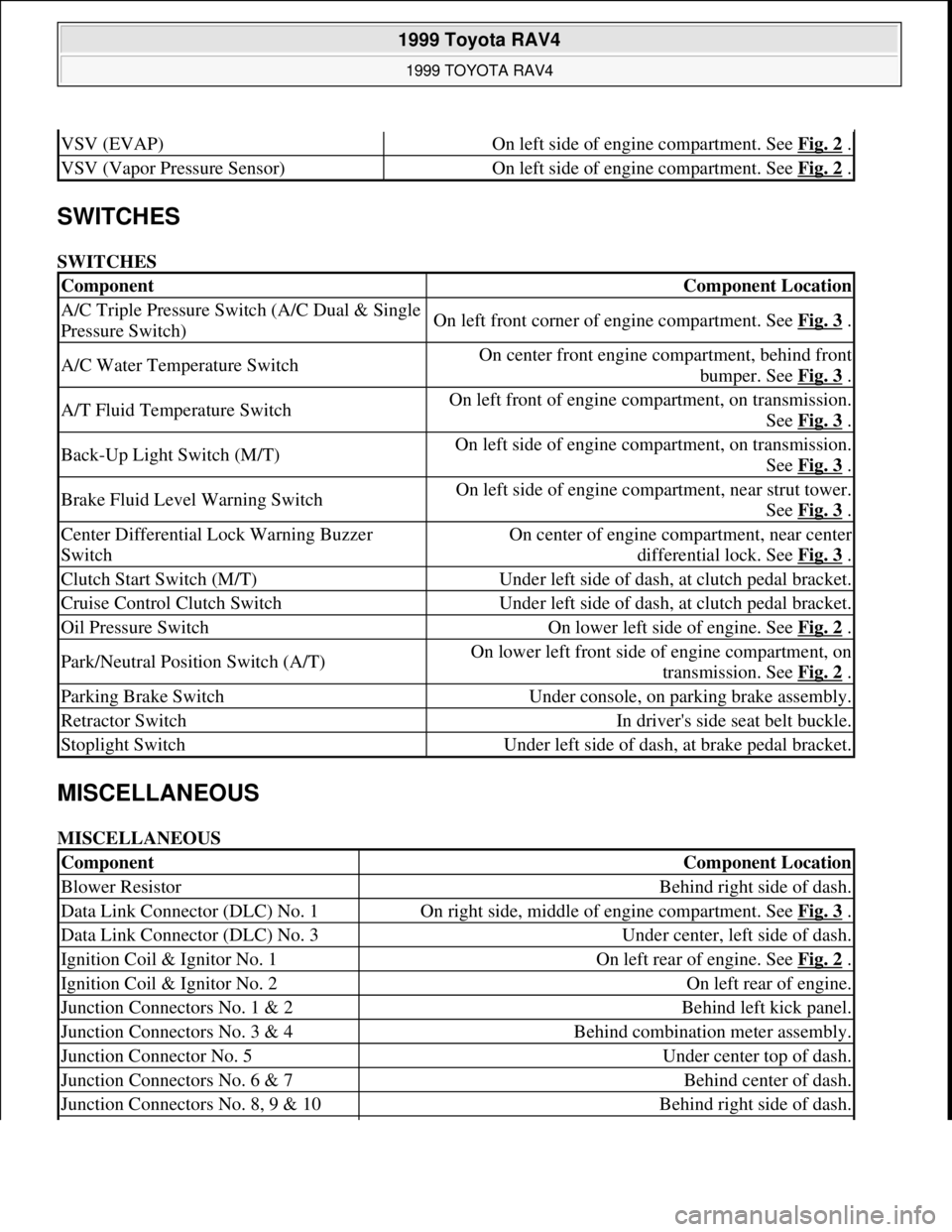
SWITCHES
MISCELLANEOUS
MISCELLANEOUS
VSV (EVAP)On left side of engine compartment. See Fig. 2 .
VSV (Vapor Pressure Sensor)On left side of engine compartment. See Fig. 2 .
ComponentComponent Location
A/C Triple Pressure Switch (A/C Dual & Single
Pressure Switch)On left front corner of engine compartment. See Fig. 3 .
A/C Water Temperature SwitchOn center front engine compartment, behind front
bumper. See Fig. 3
.
A/T Fluid Temperature SwitchOn left front of engine compartment, on transmission.
See Fig. 3
.
Back-Up Light Switch (M/T)On left side of engine compartment, on transmission.
See Fig. 3
.
Brake Fluid Level Warning SwitchOn left side of engine compartment, near strut tower.
See Fig. 3
.
Center Differential Lock Warning Buzzer
SwitchOn center of engine compartment, near center
differential lock. See Fig. 3
.
Clutch Start Switch (M/T)Under left side of dash, at clutch pedal bracket.
Cruise Control Clutch SwitchUnder left side of dash, at clutch pedal bracket.
Oil Pressure SwitchOn lower left side of engine. See Fig. 2 .
Park/Neutral Position Switch (A/T)On lower left front side of engine compartment, on
transmission. See Fig. 2
.
Parking Brake SwitchUnder console, on parking brake assembly.
Retractor SwitchIn driver's side seat belt buckle.
Stoplight SwitchUnder left side of dash, at brake pedal bracket.
ComponentComponent Location
Blower ResistorBehind right side of dash.
Data Link Connector (DLC) No. 1On right side, middle of engine compartment. See Fig. 3 .
Data Link Connector (DLC) No. 3Under center, left side of dash.
Ignition Coil & Ignitor No. 1On left rear of engine. See Fig. 2 .
Ignition Coil & Ignitor No. 2On left rear of engine.
Junction Connectors No. 1 & 2Behind left kick panel.
Junction Connectors No. 3 & 4Behind combination meter assembly.
Junction Connector No. 5Under center top of dash.
Junction Connectors No. 6 & 7Behind center of dash.
Junction Connectors No. 8, 9 & 10Behind right side of dash.
1999 Toyota RAV4
1999 TOYOTA RAV4
Microsoft
Sunday, November 22, 2009 10:17:32 AMPage 4 © 2005 Mitchell Repair Information Company, LLC.
Page 737 of 1632
CRANKSHAFT, MAIN & CONNECTING ROD BEARINGStable under ENGINE SPECIFICATIONS.
Cylinder Block
1. Inspect cylinder block deck surface warpage. Replace cylinder block if deck warpage exceeds
specification. See CYLINDER BLOCK
table under ENGINE SPECIFICATIONS.
2. Different cylinder bore diameters are used. Cylinder bore diameter may be identified by size mark ("1",
"2" or "3") on cylinder block deck surface. See Fig. 37
.
3. Measure cylinder bore diameter at 2 different places, 90 degrees apart at .39" (10.0 mm) from top and
bottom of cylinder bore and at center of cylinder bore. Ensure cylinder bore diameter is within
specification. See CYLINDER BLOCK
table under ENGINE SPECIFICATIONS.
4. Bore cylinder block for oversize pistons if cylinder bore diameter is not within specification. Pistons are
available in .020" (.50 mm) oversize.
5. Install main bearing caps in numerical sequence with No. 1 at timing belt end, and No. 5 at flywheel/drive
plate end of engine. Ensure arrow on top of main bearing cap points toward timing belt end of engine.
6. Install and tighten main bearing cap bolts to specification in sequence. See Fig. 36
. See TORQUE
SPECIFICATIONS .
7. Ensure main bearing bore inside diameter is within specification. See CYLINDER BLOCK
table under
ENGINE SPECIFICATIONS.
ENGINE OILING
ENGINE LUBRICATION SYSTEM
Crankshaft driven oil pump provides pressurized engine lubrication. Oil cooler is installed between oil filter and
cylinder block.
Crankcase Capacity
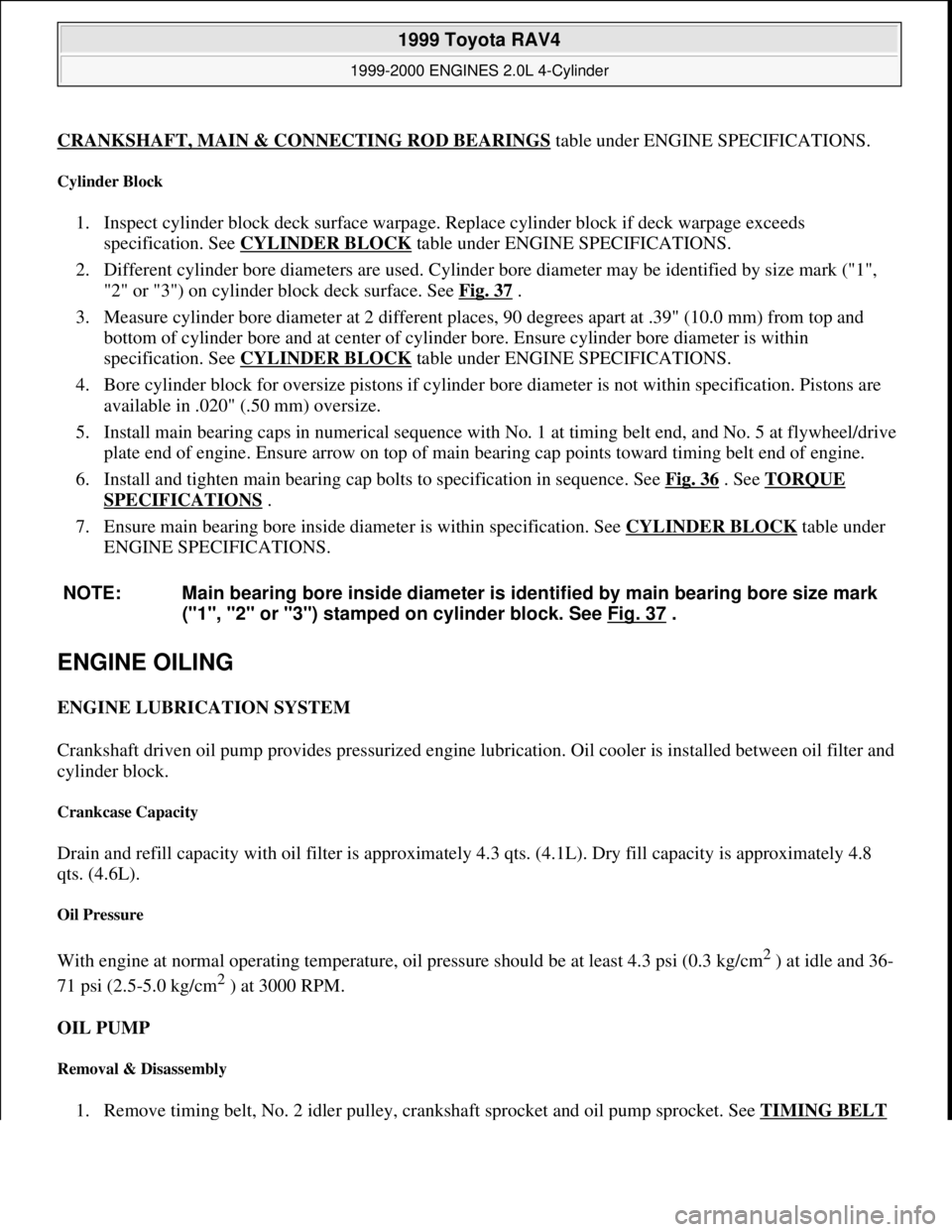
Drain and refill capacity with oil filter is approximately 4.3 qts. (4.1L). Dry fill capacity is approximately 4.8
qts. (4.6L).
Oil Pressure
With engine at normal operating temperature, oil pressure should be at least 4.3 psi (0.3 kg/cm2 ) at idle and 36-
71 psi (2.5-5.0 kg/cm
2 ) at 3000 RPM.
OIL PUMP
Removal & Disassembly
1. Remove timing belt, No. 2 idler pulley, crankshaft sprocket and oil pump sprocket. See TIMING BELT
NOTE: Main bearing bore inside diameter is identified by main bearing bore size mark
("1", "2" or "3") stamped on cylinder block. See Fig. 37
.
1999 Toyota RAV4
1999-2000 ENGINES 2.0L 4-Cylinder
Microsoft
Sunday, November 22, 2009 10:22:27 AMPage 54 © 2005 Mitchell Repair Information Company, LLC.
Page 805 of 1632
CRANKSHAFT, MAIN & CONNECTING ROD BEARINGSunder ENGINE SPECIFICATIONS.
Cylinder Block
1. Inspect cylinder block deck surface warpage. Replace cylinder block if deck warpage exceeds
specification. See CYLINDER BLOCK
under ENGINE SPECIFICATIONS.
2. Different cylinder bore diameters are used. Cylinder bore diameter may be identified by size mark ("1",
"2" or "3") on cylinder block deck surface. See Fig. 39
.
3. Measure cylinder bore diameter at 2 different places, 90 degrees apart at .39" (10.0 mm) from top and
bottom of cylinder bore and at center of cylinder bore. Ensure cylinder bore diameter is within
specification. See CYLINDER BLOCK
under ENGINE SPECIFICATIONS.
4. Bore cylinder block for oversize pistons if cylinder bore diameter is not within specification. Pistons are
available in .020" (.50 mm) oversize.
5. Install main bearing caps in numerical sequence with No. 1 at timing belt end and No. 5 at flywheel/drive
plate end of engine. Ensure arrow on top of main bearing cap points toward timing belt end of engine.
6. Install and tighten main bearing cap bolts to specification in sequence. See Fig. 38
. See TORQUE
SPECIFICATIONS .
7. Ensure main bearing bore inside diameter is within specification. See CYLINDER BLOCK
under
ENGINE SPECIFICATIONS.
ENGINE OILING
ENGINE LUBRICATION SYSTEM
Crankshaft driven oil pump provides pressurized engine lubrication. Oil cooler is installed between oil filter and
cylinder block.
Crankcase Capacity
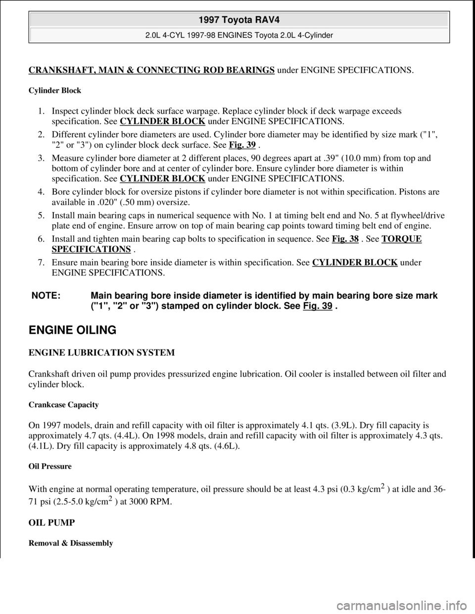
On 1997 models, drain and refill capacity with oil filter is approximately 4.1 qts. (3.9L). Dry fill capacity is
approximately 4.7 qts. (4.4L). On 1998 models, drain and refill capacity with oil filter is approximately 4.3 qts.
(4.1L). Dry fill capacity is approximately 4.8 qts. (4.6L).
Oil Pressure
With engine at normal operating temperature, oil pressure should be at least 4.3 psi (0.3 kg/cm2 ) at idle and 36-
71 psi (2.5-5.0 kg/cm
2 ) at 3000 RPM.
OIL PUMP
Removal & Disassembly
NOTE: Main bearing bore inside diameter is identified by main bearing bore size mark
("1", "2" or "3") stamped on cylinder block. See Fig. 39
.
1997 Toyota RAV4
2.0L 4-CYL 1997-98 ENGINES Toyota 2.0L 4-Cylinder
Microsoft
Sunday, November 22, 2009 10:23:31 AMPage 57 © 2005 Mitchell Repair Information Company, LLC.
Page 814 of 1632
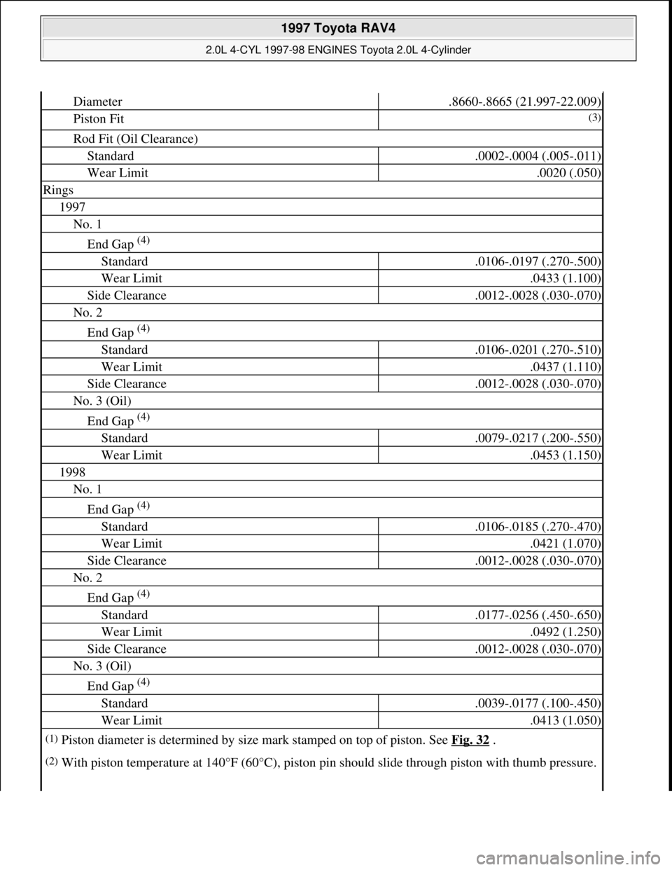
Diameter.8660-.8665 (21.997-22.009)
Piston Fit(3)
Rod Fit (Oil Clearance)
Standard.0002-.0004 (.005-.011)
Wear Limit.0020 (.050)
Rings
1997
No. 1
End Gap (4)
Standard.0106-.0197 (.270-.500)
Wear Limit.0433 (1.100)
Side Clearance.0012-.0028 (.030-.070)
No. 2
End Gap (4)
Standard.0106-.0201 (.270-.510)
Wear Limit.0437 (1.110)
Side Clearance.0012-.0028 (.030-.070)
No. 3 (Oil)
End Gap (4)
Standard.0079-.0217 (.200-.550)
Wear Limit.0453 (1.150)
1998
No. 1
End Gap (4)
Standard.0106-.0185 (.270-.470)
Wear Limit.0421 (1.070)
Side Clearance.0012-.0028 (.030-.070)
No. 2
End Gap (4)
Standard.0177-.0256 (.450-.650)
Wear Limit.0492 (1.250)
Side Clearance.0012-.0028 (.030-.070)
No. 3 (Oil)
End Gap (4)
Standard.0039-.0177 (.100-.450)
Wear Limit.0413 (1.050)
(1)Piston diameter is determined by size mark stamped on top of piston. See Fig. 32 .
(2)With piston temperature at 140°F (60°C), piston pin should slide through piston with thumb pressure.
1997 Toyota RAV4
2.0L 4-CYL 1997-98 ENGINES Toyota 2.0L 4-Cylinder
Microsoft
Sunday, November 22, 2009 10:23:31 AMPage 66 © 2005 Mitchell Repair Information Company, LLC.
Page 874 of 1632
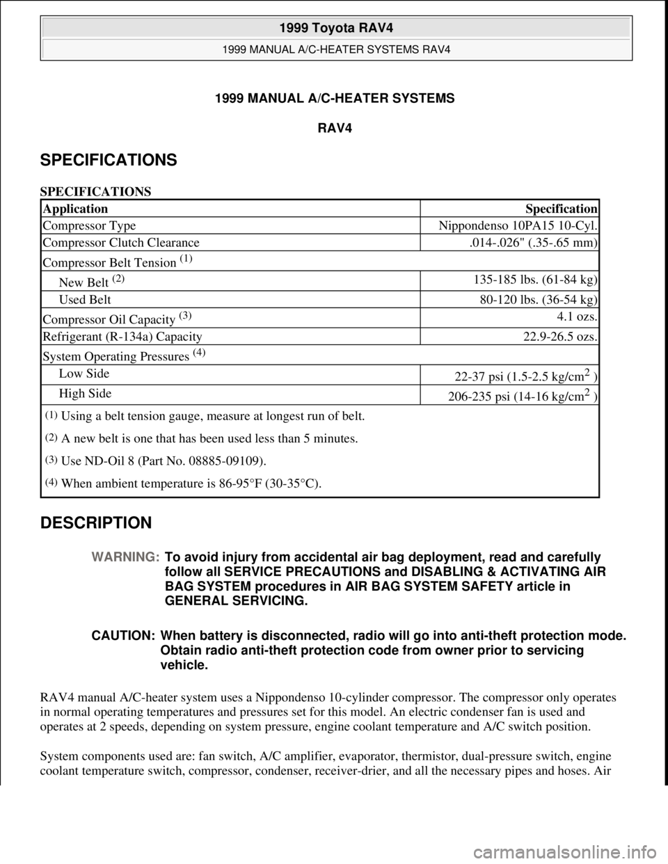
1999 MANUAL A/C-HEATER SYSTEMS
RAV4
SPECIFICATIONS
SPECIFICATIONS
DESCRIPTION
RAV4 manual A/C-heater system uses a Nippondenso 10-cylinder compressor. The compressor only operates
in normal operating temperatures and pressures set for this model. An electric condenser fan is used and
operates at 2 speeds, depending on system pressure, engine coolant temperature and A/C switch position.
System components used are: fan switch, A/C amplifier, evaporator, thermistor, dual-pressure switch, engine
coolant temperature switch, compressor, condenser, receive
r-drier, and all the necessary pipes and hoses. Air
ApplicationSpecification
Compressor TypeNippondenso 10PA15 10-Cyl.
Compressor Clutch Clearance.014-.026" (.35-.65 mm)
Compressor Belt Tension (1)
New Belt (2) 135-185 lbs. (61-84 kg)
Used Belt80-120 lbs. (36-54 kg)
Compressor Oil Capacity (3) 4.1 ozs.
Refrigerant (R-134a) Capacity22.9-26.5 ozs.
System Operating Pressures (4)
Low Side22-37 psi (1.5-2.5 kg/cm2 )
High Side206-235 psi (14-16 kg/cm2 )
(1)Using a belt tension gauge, measure at longest run of belt.
(2)A new belt is one that has been used less than 5 minutes.
(3)Use ND-Oil 8 (Part No. 08885-09109).
(4)When ambient temperature is 86-95°F (30-35°C).
WARNING:To avoid injury from accidental air bag deployment, read and carefully
follow all SERVICE PRECAUTIONS and DISABLING & ACTIVATING AIR
BAG SYSTEM procedures in AIR BAG SYSTEM SAFETY article in
GENERAL SERVICING.
CAUTION: When battery is disconnected, radio will go into anti-theft protection mode.
Obtain radio anti-theft protection code from owner prior to servicing
vehicle.
1999 Toyota RAV4
1999 MANUAL A/C-HEATER SYSTEMS RAV4
1999 Toyota RAV4
1999 MANUAL A/C-HEATER SYSTEMS RAV4
Microsoft
Sunday, November 22, 2009 10:29:27 AMPage 1 © 2005 Mitchell Repair Information Company, LLC.
Microsoft
Sunday, November 22, 2009 10:29:33 AMPage 1 © 2005 Mitchell Repair Information Company, LLC.