battery replacement TOYOTA RAV4 1996 Service Repair Manual
[x] Cancel search | Manufacturer: TOYOTA, Model Year: 1996, Model line: RAV4, Model: TOYOTA RAV4 1996Pages: 1632, PDF Size: 41.64 MB
Page 37 of 1632
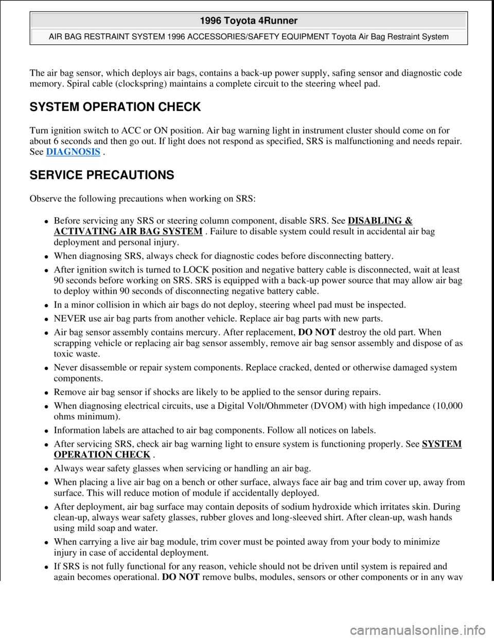
The air bag sensor, which deploys air bags, contains a back-up power supply, safing sensor and diagnostic code
memory. Spiral cable (clockspring) maintains a complete circuit to the steering wheel pad.
SYSTEM OPERATION CHECK
Turn ignition switch to ACC or ON position. Air bag warning light in instrument cluster should come on for
about 6 seconds and then go out. If light does not respond as specified, SRS is malfunctioning and needs repair.
See DIAGNOSIS
.
SERVICE PRECAUTIONS
Observe the following precautions when working on SRS:
Before servicing any SRS or steering column component, disable SRS. See DISABLING &
ACTIVATING AIR BAG SYSTEM . Failure to disable system could result in accidental air bag
deployment and personal injury.
When diagnosing SRS, always check for diagnostic codes before disconnecting battery.
After ignition switch is turned to LOCK position and negative battery cable is disconnected, wait at least
90 seconds before working on SRS. SRS is equipped with a back-up power source that may allow air bag
to deploy within 90 seconds of disconnecting negative battery cable.
In a minor collision in which air bags do not deploy, steering wheel pad must be inspected.
NEVER use air bag parts from another vehicle. Replace air bag parts with new parts.
Air bag sensor assembly contains mercury. After replacement, DO NOT destroy the old part. When
scrapping vehicle or replacing air bag sensor assembly, remove air bag sensor assembly and dispose of as
toxic waste.
Never disassemble or repair system components. Replace cracked, dented or otherwise damaged system
components.
Remove air bag sensor if shocks are likely to be applied to the sensor during repairs.
When diagnosing electrical circuits, use a Digital Volt/Ohmmeter (DVOM) with high impedance (10,000
ohms minimum).
Information labels are attached to air bag components. Follow all notices on labels.
After servicing SRS, check air bag warning light to ensure system is functioning properly. See SYSTEM
OPERATION CHECK .
Always wear safety glasses when servicing or handling an air bag.
When placing a live air bag on a bench or other surface, always face air bag and trim cover up, away from
surface. This will reduce motion of module if accidentally deployed.
After deployment, air bag surface may contain deposits of sodium hydroxide which irritates skin. During
clean-up, always wear safety glasses, rubber gloves and long-sleeved shirt. After clean-up, wash hands
using mild soap and water.
When carrying a live air bag module, trim cover must be pointed away from your body to minimize
injury in case of accidental deployment.
If SRS is not fully functional for any reason, vehicle should not be driven until system is repaired and
a
gain becomes operational. DO NOTremove bulbs, modules, sensors or other components or in any way
1996 Toyota 4Runner
AIR BAG RESTRAINT SYSTEM 1996 ACCESSORIES/SAFETY EQUIPMENT Toyota Air Bag Restraint System
Microsoft
Tuesday, August 18, 2009 7:33:32 PMPage 3 © 2005 Mitchell Repair Information Company, LLC.
Page 51 of 1632
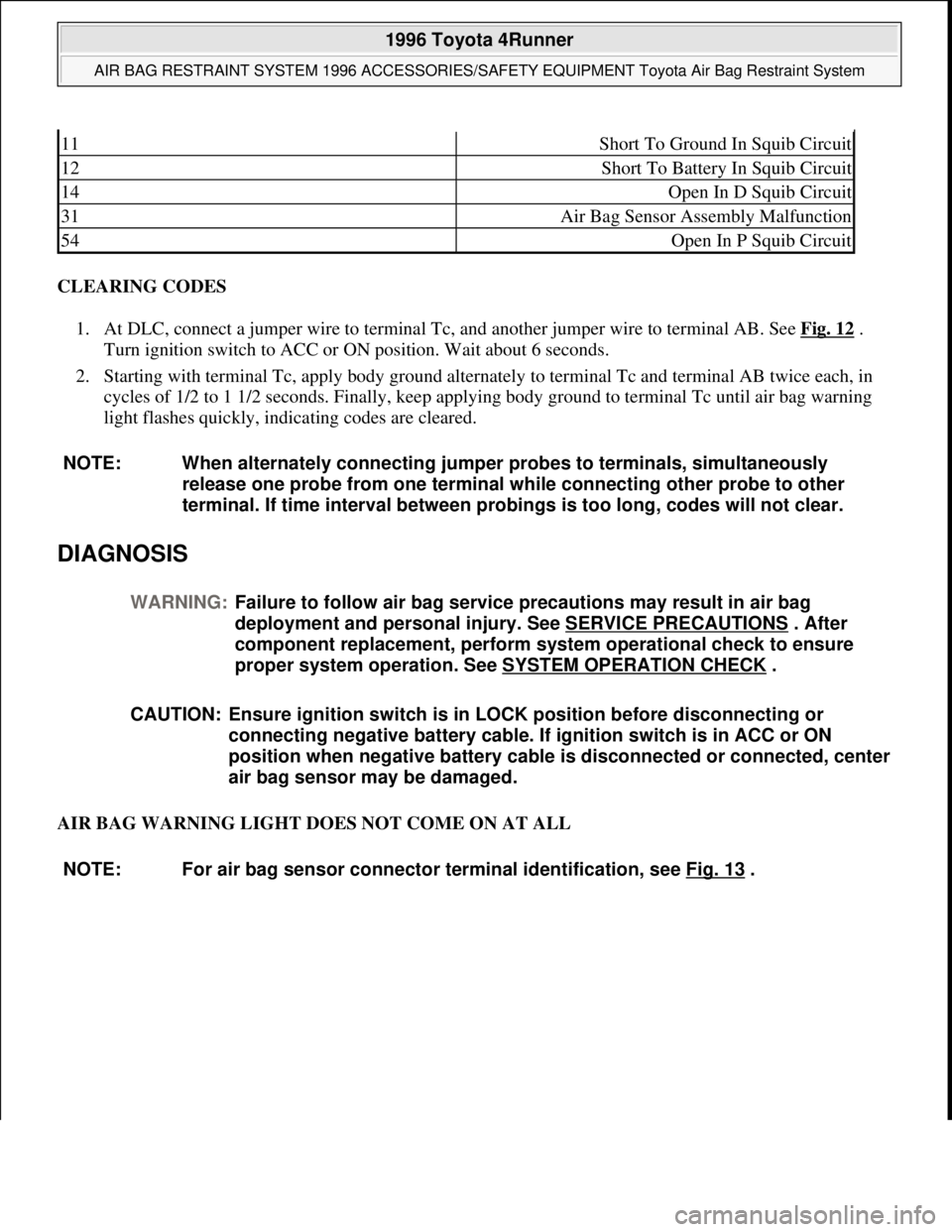
CLEARING CODES
1. At DLC, connect a jumper wire to terminal Tc, and another jumper wire to terminal AB. See Fig. 12
.
Turn ignition switch to ACC or ON position. Wait about 6 seconds.
2. Starting with terminal Tc, apply body ground alternately to terminal Tc and terminal AB twice each, in
cycles of 1/2 to 1 1/2 seconds. Finally, keep applying body ground to terminal Tc until air bag warning
light flashes quickly, indicating codes are cleared.
DIAGNOSIS
AIR BAG WARNING LIGHT DOES NOT COME ON AT ALL
11Short To Ground In Squib Circuit
12Short To Battery In Squib Circuit
14Open In D Squib Circuit
31Air Bag Sensor Assembly Malfunction
54Open In P Squib Circuit
NOTE: When alternately connecting jumper probes to terminals, simultaneously
release one probe from one terminal while connecting other probe to other
terminal. If time interval between probings is too long, codes will not clear.
WARNING:Failure to follow air bag service precautions may result in air bag
deployment and personal injury. See SERVICE PRECAUTIONS
. After
component replacement, perform system operational check to ensure
proper system operation. See SYSTEM OPERATION CHECK
.
CAUTION: Ensure ignition switch is in LOCK position before disconnecting or
connecting negative battery cable. If ignition switch is in ACC or ON
position when negative battery cable is disconnected or connected, center
air bag sensor may be damaged.
NOTE: For air bag sensor connector terminal identification, see Fig. 13
.
1996 Toyota 4Runner
AIR BAG RESTRAINT SYSTEM 1996 ACCESSORIES/SAFETY EQUIPMENT Toyota Air Bag Restraint System
Microsoft
Tuesday, August 18, 2009 7:33:32 PMPage 17 © 2005 Mitchell Repair Information Company, LLC.
Page 66 of 1632
may allow air bag to deploy until 90 seconds after disconnecting negative battery cable.
If vehicle was in a minor collision but air bags did not deploy, inspect all system components for any sign
of damage, and replace as necessary.
Never use air bag system components from another vehicle. Replace air bag system components with new
parts.
Remove air bag sensor assembly if repairing the vehicle requires impacting (shocking) the vehicle.
Air bag sensor assembly contains mercury. After replacement, DO NOT destroy old part. When
scrapping vehicle or replacing air bag sensor assembly, remove air bag sensor assembly and dispose of it
as toxic waste.
Never disassemble and repair air bag sensor assembly, front air bag sensors, passenger-side or driver-side
air bag modules or seat belt pretensioners.
Replace dropped, cracked, dented or otherwise damaged components.
DO NOT expose air bag sensor assembly, front air bag sensors or air bag modules directly to heat or
flame.
When diagnosing electrical circuits, use a volt/ohm meter with high impedance (10,000 ohms minimum).
Information labels are attached to air bag components. Follow all notices on labels.
After work on air bag system is complete, check AIR BAG warning light to ensure system is functioning
properly. See SYSTEM OPERATION CHECK
.
Always wear safety glasses when servicing or handling an air bag.
When placing a live air bag on a bench or other surface, always face air bag and trim cover up and away
from surface. This will reduce motion of module if it is accidentally deployed.
After deployment, air bag surface may contain deposits of sodium hydroxide, which irritates skin. Always
wear safety glasses, rubber gloves, and long-sleeved shirt during clean-up. After clean-up, wash hands
using mild soap and water.
Carry a live air bag module with trim cover (air bag) pointed away from your body to minimize injury in
case accidental deployment.
If air bag system is not fully functional for any reason, vehicle should not be driven until system is
repaired and again becomes operational. DO NOT remove bulbs, modules, sensors or other components,
or in any way disable system from operating normally. If air bag system is not functional, park vehicle
until it is repaired and functions properly.
ADJUSTMENTS
SPIRAL CABLE
Ensure front wheels are in straight-ahead position. Turn spiral cable counterclockwise until it becomes difficult
to turn. Turn spiral cable clockwise about 2 1/2 turns to align match marks. See Fig. 2
. Install steering wheel.
1999 Toyota RAV4
AIR BAG RESTRAINT SYSTEM 1999 Toyota
Microsoft
Sunday, November 22, 2009 10:33:22 AMPage 3 © 2005 Mitchell Repair Information Company, LLC.
Page 67 of 1632
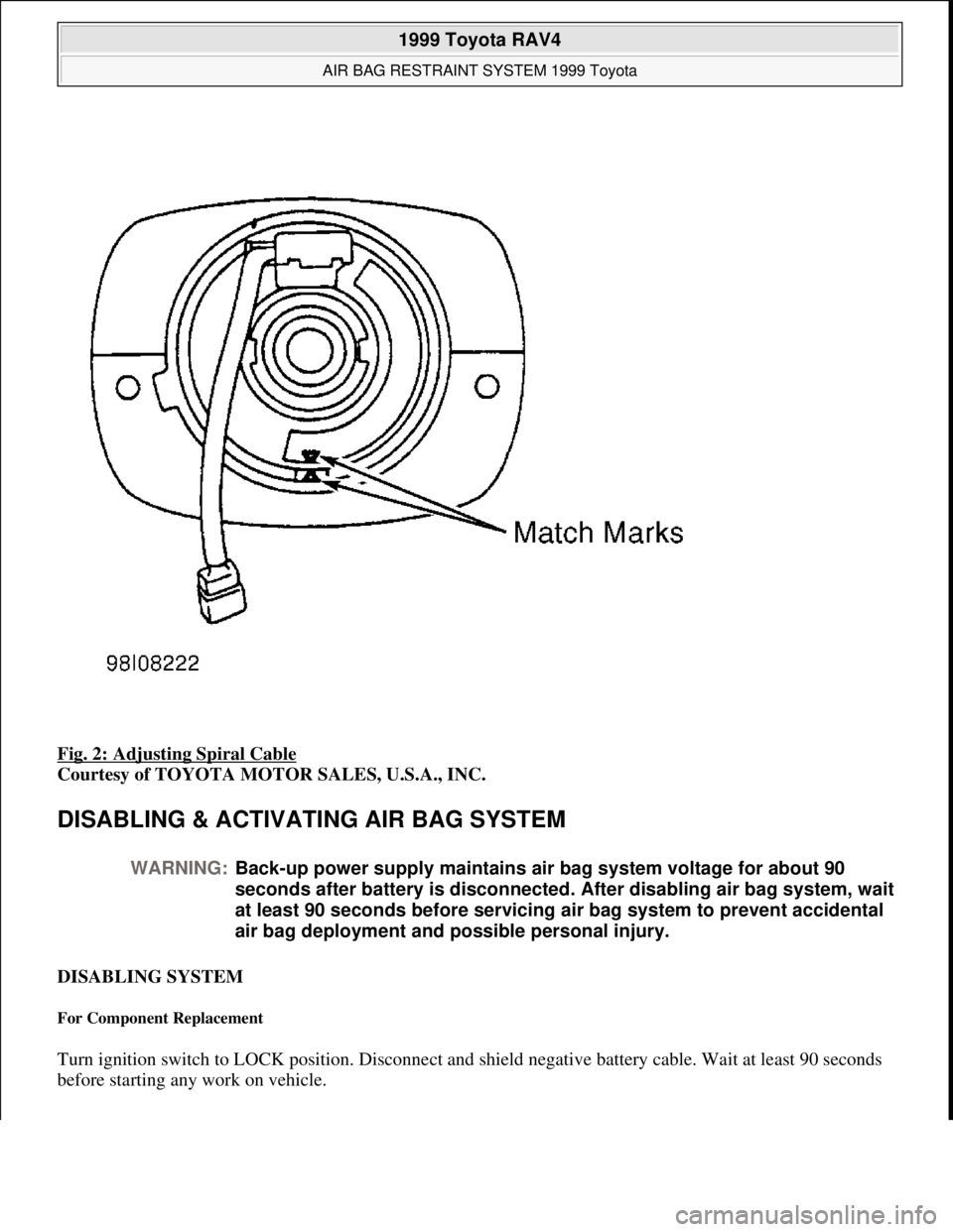
Fig. 2: Adjusting Spiral Cable
Courtesy of TOYOTA MOTOR SALES, U.S.A., INC.
DISABLING & ACTIVATING AIR BAG SYSTEM
DISABLING SYSTEM
For Component Replacement
Turn ignition switch to LOCK position. Disconnect and shield negative battery cable. Wait at least 90 seconds
before starting any work on vehicle.
WARNING:Back-up power supply maintains air bag system voltage for about 90
seconds after battery is disconnected. After disabling air bag system, wait
at least 90 seconds before servicing air bag system to prevent accidental
air bag deployment and possible personal injury.
1999 Toyota RAV4
AIR BAG RESTRAINT SYSTEM 1999 Toyota
Microsoft
Sunday, November 22, 2009 10:33:22 AMPage 4 © 2005 Mitchell Repair Information Company, LLC.
Page 69 of 1632
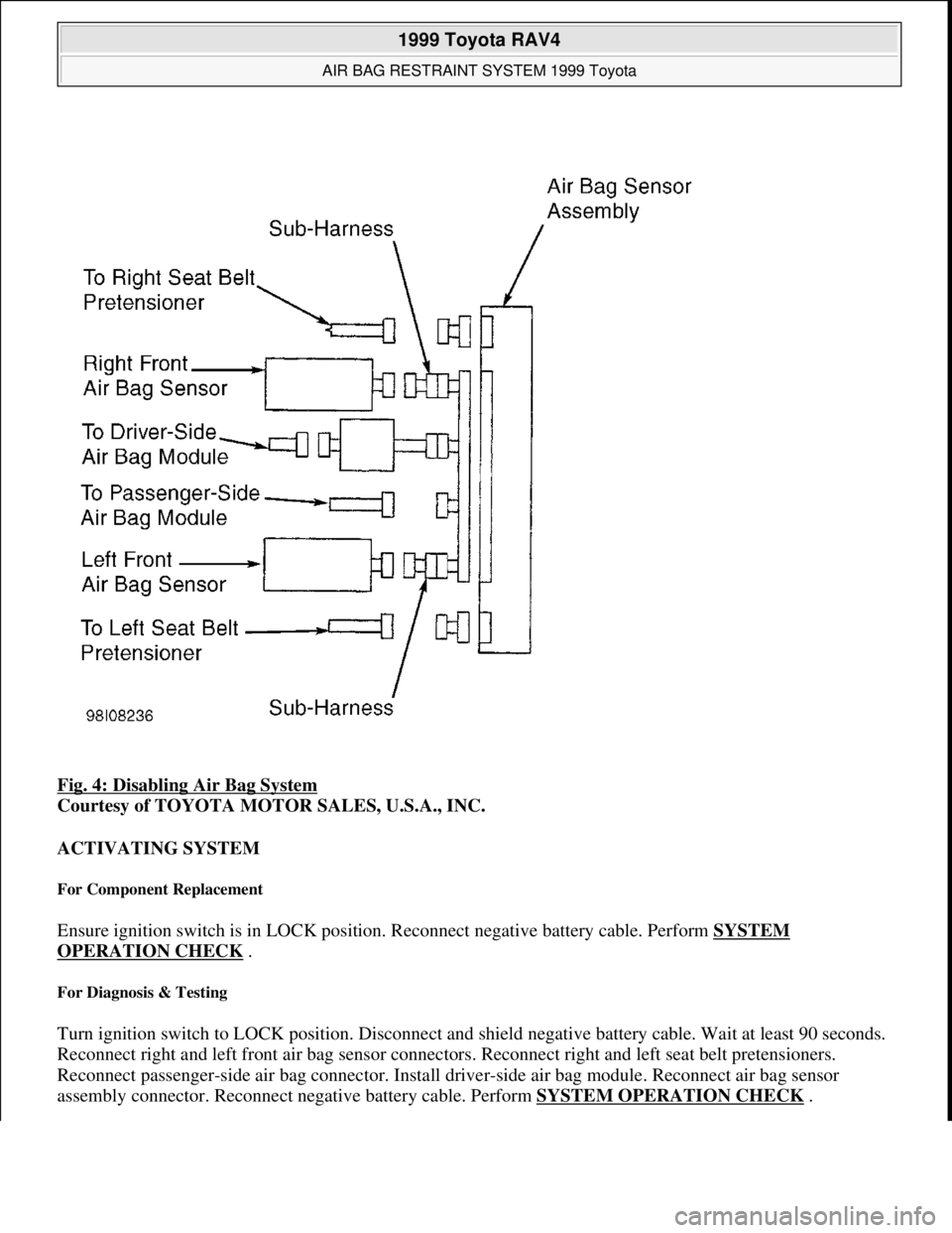
Fig. 4: Disabling Air Bag System
Courtesy of TOYOTA MOTOR SALES, U.S.A., INC.
ACTIVATING SYSTEM
For Component Replacement
Ensure ignition switch is in LOCK position. Reconnect negative battery cable. Perform SYSTEM
OPERATION CHECK .
For Diagnosis & Testing
Turn ignition switch to LOCK position. Disconnect and shield negative battery cable. Wait at least 90 seconds.
Reconnect right and left front air bag sensor connectors. Reconnect right and left seat belt pretensioners.
Reconnect passenger-side air bag connector. Install driver-side air bag module. Reconnect air bag sensor
assembl
y connector. Reconnect negative battery cable. Perform SYSTEM OPERATION CHECK.
1999 Toyota RAV4
AIR BAG RESTRAINT SYSTEM 1999 Toyota
Microsoft
Sunday, November 22, 2009 10:33:22 AMPage 6 © 2005 Mitchell Repair Information Company, LLC.
Page 76 of 1632
REMOVAL & INSTALLATION
AIR BAG SENSOR ASSEMBLY
Removal & Installation
1. Before proceeding, see SERVICE PRECAUTIONS . Air bag sensor assembly is located on the floor
inside center console box. See Fig. 10
. Turn ignition switch to LOCK position. Disconnect negative
battery cable. Wait at least 90 seconds.
2. Remove shift lever and boot. Ash tray and console box hole cover. Remove console box. Remove 4 Torx
screws retaining air bag sensor assembly. Remove air bag sensor assembly.
3. To install, reverse removal procedure. Tighten air bag sensor assembly Torx screws to specification. See
TORQUE SPECIFICATIONS
. Check AIR BAG warning light to ensure system is functioning
properl
y. See SYSTEM OPERATION CHECK. WARNING:Failure to follow service precautions may result in air bag deployment and
personal injury. See SERVICE PRECAUTIONS
. After component
replacement, check system operation. See SYSTEM OPERATION CHECK
.
1999 Toyota RAV4
AIR BAG RESTRAINT SYSTEM 1999 Toyota
Microsoft
Sunday, November 22, 2009 10:33:22 AMPage 13 © 2005 Mitchell Repair Information Company, LLC.
Page 88 of 1632
Fig. 15: Releasing Shorting Spring
Courtesy of TOYOTA MOTOR SALES, U.S.A., INC.
DIAGNOSTIC TESTS
AIR BAG WARNING LIGHT DOES NOT ILLUMINATE
Description
AIR BAG warning light is located in instrument cluster. When air bag system is normal, AIR BAG warning
light illuminates for about 6 seconds after ignition switch is turned from LOCK to ACC or ON position, and
turns off automatically. If a malfunction is present in air bag system, AIR BAG warning light illuminates to
inform operator of malfunction. When Data Link Connector 1 (DLC1) terminals Tc and E1 are connected
together, a Diagnostic Trouble Code (DTC) is displayed by flashing AIR BAG warning light.
Diagnostic Procedure
1. Remove SRS-B fuse and check continuity across fuse blades. SRS-B fuse is located in instrument panel
fuse block under left side of instrument panel. If fuse is faulty, go to step 4). If fuse is okay, reinstall fuse
and go to next step.
2. Disable air bag system. See DISABLING SYSTEM
under DISABLING & ACTIVATING AIR BAG
SYSTEM. Reconnect negative battery cable. Turn ignition switch to ACC or ON position. Measure
voltage between ground and harness side of air bag sensor assembly connector C20, terminal No. 3
(circuit LA, Black/Yellow wire). See Fig. 16
. If 10-14 volts is not present, repair AIR BAG warning
light bulb or circuit. If 10-14 volts is present, go to next step.
3. Turn ignition switch to LOCK position. Disconnect negative battery cable. Reconnect 3 air bag sensor
assembly connectors. Leave air bag modules, pretensioners and front air bag sensors disconnected.
Reconnect negative battery cable and wait at least 2 seconds. Turn ignition switch to ACC or ON
position. If AIR BAG warning light illuminates, system operation is normal. If AIR BAG warning light
does not come on, check for poor connection at air bag sensor assembly connector C20, terminal No. 3
(Black/Yellow wire). If connection is oka
y, replace air bag sensor assembly. WARNING:Failure to follow service precautions may result in air bag deployment and
personal injury. See SERVICE PRECAUTIONS
. After component
replacement, check system operation. See SYSTEM OPERATION CHECK
.
CAUTION: Ensure ignition switch is in LOCK position before disconnecting or
connecting negative battery cable. If ignition switch is in ACC or ON
position when negative battery cable is disconnected or connected, air
bag sensor may be damaged. To prevent damage to connector terminals,
DO NOT probe terminal ends. Instead, backprobe terminals (probe
terminal where wire enters harness connector).
NOTE: In the following tests, the term squib connector and module connector may be
used interchangeably.
1999 Toyota RAV4
AIR BAG RESTRAINT SYSTEM 1999 Toyota
Microsoft
Sunday, November 22, 2009 10:33:23 AMPage 25 © 2005 Mitchell Repair Information Company, LLC.
Page 950 of 1632
On models equipped with anti-lock brake systems, ALWAYS observe the following cautions:
DO NOT attempt to bleed hydraulic system without first referring to the appropriate ANTI-LOCK
BRAKE SYSTEM article in the BRAKES Section.
DO NOT mix tire sizes. As long as tires remain close to the original diameter, increasing the width is
acceptable. Rolling diameter must be identical for all 4 tires. Some manufacturers recommend tires of the
same brand, style and type. Failure to follow this precaution may cause inaccurate wheel speed readings.
Use ONLY recommended brake fluids. DO NOT use silicone brake fluids in an ABS-equipped vehicle.
BATTERY WARNING
REPLACING BLOWN FUSES
BRAKE PAD WEAR INDICATOR
Indicator will cause a squealing or scraping noise, warning that brake pads need replacement.
CATALYTIC CONVERTER CAUTION: The anti-lock brake system contains electronic equipment that can be
susceptible to interference caused by improperly installed or high output
radio transmitting equipment. Since this interference could cause the
possible loss of the anti-lock braking capability, such equipment should
be installed by qualified professionals.
WARNING:When battery is disconnected, vehicles equipped with computers may
lose memory data. When battery power is restored, driveability problems
may exist on some vehicles. These vehicles may require a relearn
procedure. See COMPUTER RELEARN PROCEDURES article in GENERAL
INFORMATION section.
CAUTION: Before replacing a blown fuse, remove ignition key, turn off all lights and
accessories to avoid damaging the electrical system. Be sure to use fuse
with the correct indicated amperage rating. The use of an incorrect
amperage rating fuse may result in a dangerous electrical system
overload.
CAUTION: Continued operation of vehicle with a severe malfunction could cause
converter to overheat, resulting in possible damage to converter and
vehicle.
CAUTION: Any modification to the exhaust system on turbo models, which reduces
exhaust backpressure, will lead to lean fuel mixtures and excessive spark
advance. This could cause serious engine damage.
1999 Toyota RAV4
MAINTENANCE INFORMATION 1997-99 MAINTENANCE Toyota Maintenance Information
Microsoft
Sunday, November 22, 2009 10:32:42 AMPage 8 © 2005 Mitchell Repair Information Company, LLC.
Page 952 of 1632
Covers any repair or replacement of parts which becomes necessary due to defects in materials or workmanship
under normal use for 36 months or 36,000 miles from in-service date.
The items specified below are covered for a period different from the basic coverage:
Air Conditioner
The air conditioner refrigerant charge is covered for the first 12 months, regardless of mileage, unless done as
part of a warranty repair.
Adjustments
Service adjustment (minor repairs not usually associated with the replacement of parts) are covered for the first
12 months or 12,500 miles, whichever occurs first.
POWERTRAIN WARRANTY
Engine, transmission, front wheel drive, rear wheel drive and restraint system are warranted against defects in
materials or workmanship under normal use for 5 years or 60,000 miles, whichever occurs first. See copy of
warranty for specific components covered.
CORROSION PERFORATION WARRANTY
Covers any repair or replacement to body sheet metal which develops corrosion perforation (hole through
panel), in normal use, due to defects in material or workmanship for a period of 5 years, regardless of mileage.
BATTERY WARRANTY
Covers replacement of defective original battery for first 12 months or 12,000 miles. After the first 12 months
or 12,000 miles, warranty covers a pro-rated amount based on months in service, up to a maximum of 36
months.
EMISSION SYSTEM DEFECT WARRANTY (EXCEPT CALIFORNIA)
Warrants to the retail purchaser, and subsequent purchaser that vehicle was designed, built, and equipped so as
to conform at the time of sale with applicable emission regulations and that it is free from defects in materials or
workmanship which may cause the vehicle to fail to conform with applicable regulations for 5 years or 50,000
miles, whichever occurs first.
EMISSION SYSTEM PERFORMANCE WARRANTY (EXCEPT CALIFORNIA)
Covers all repairs, adjustments, or replacements if vehicle fails to conform to applicable emission standards and
such failure results in the vehicle owner having to bear a penalty or other sanction under local, state or federal
law for 5 years or 50,000 miles, whichever comes first. If the vehicle has been in use for more than 24 months
or 24,000 miles, the manufacturer will make the necessary adjustments, repairs or replacements at no cost to the
owner only when noncompliance is caused by failure of components which have been installed in the vehicle
for the sole or primary purpose of reducing vehicle emissions. See copy of warranty for specific components
1999 Toyota RAV4
MAINTENANCE INFORMATION 1997-99 MAINTENANCE Toyota Maintenance Information
Microsoft
Sunday, November 22, 2009 10:32:42 AMPage 10 © 2005 Mitchell Repair Information Company, LLC.