TOYOTA RAV4 2006 Service Repair Manual
Manufacturer: TOYOTA, Model Year: 2006, Model line: RAV4, Model: TOYOTA RAV4 2006Pages: 2000, PDF Size: 45.84 MB
Page 1391 of 2000
DRIVE SHAFT – FRONT DRIVE SHAFT ASSEMBLY (for 4WD)DS–37
DS
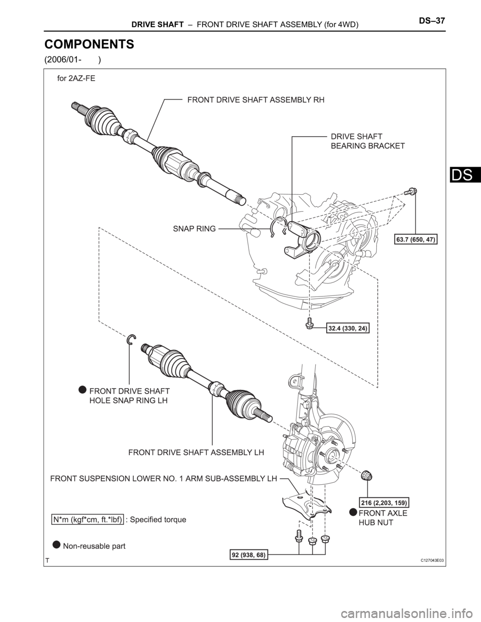
COMPONENTS
(2006/01- )
C127043E03
Page 1392 of 2000
DS–38DRIVE SHAFT – FRONT DRIVE SHAFT ASSEMBLY (for 4WD)
DS
C137745E01
Page 1393 of 2000
DRIVE SHAFT – FRONT DRIVE SHAFT ASSEMBLY (for 4WD)DS–39
DS
C127046E06
Page 1394 of 2000
DS–40DRIVE SHAFT – FRONT DRIVE SHAFT ASSEMBLY (for 4WD)
DS
REMOVAL
(2005/11-2006/01)
1. REMOVE FRONT WHEEL
2. DRAIN AUTOMATIC TRANSAXLE FLUID
(a) Drain the automatic transaxle fluid for U140F (see
page AX-147).
(b) Drain the automatic transaxle fluid for U241E (see
page AX-146).
3. REMOVE FRONT AXLE HUB NUT (See page AH-6)
4. DISCONNECT FRONT SPEED SENSOR LH (See page
BC-191)
5. DISCONNECT FRONT SPEED SENSOR RH
HINT:
Use the same procedures described for the LH side.
6. DISCONNECT FRONT DISC BRAKE CYLINDER
ASSEMBLY LH (See page BR-40)
7. DISCONNECT FRONT DISC BRAKE CYLINDER
ASSEMBLY RH
HINT:
Use the same procedures described for the LH side.
8. DISCONNECT FRONT STABILIZER LINK ASSEMBLY
LH (See page SP-9)
9. DISCONNECT FRONT STABILIZER LINK ASSEMBLY
RH
HINT:
Use the same procedures described for the LH side.
10. DISCONNECT FRONT SUSPENSION LOWER NO. 1
ARM SUB-ASSEMBLY LH (See page AH-7)
11. DISCONNECT FRONT SUSPENSION LOWER NO. 1
ARM SUB-ASSEMBLY RH
HINT:
Use the same procedures described for the LH side.
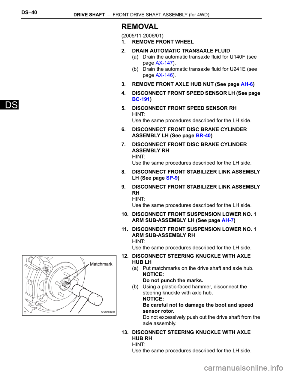
12. DISCONNECT STEERING KNUCKLE WITH AXLE
HUB LH
(a) Put matchmarks on the drive shaft and axle hub.
NOTICE:
Do not punch the marks.
(b) Using a plastic-faced hammer, disconnect the
steering knuckle with axle hub.
NOTICE:
Be careful not to damage the boot and speed
sensor rotor.
Do not excessively push out the drive shaft from the
axle assembly.
13. DISCONNECT STEERING KNUCKLE WITH AXLE
HUB RH
HINT:
Use the same procedures described for the LH side.
C129488E01
Page 1395 of 2000
DRIVE SHAFT – FRONT DRIVE SHAFT ASSEMBLY (for 4WD)DS–41
DS
14. DISCONNECT TIE ROD END SUB-ASSEMBLY LH
(See page PS-42)
15. DISCONNECT TIE ROD END SUB-ASSEMBLY RH
HINT:
Use the same procedures described for the LH side.
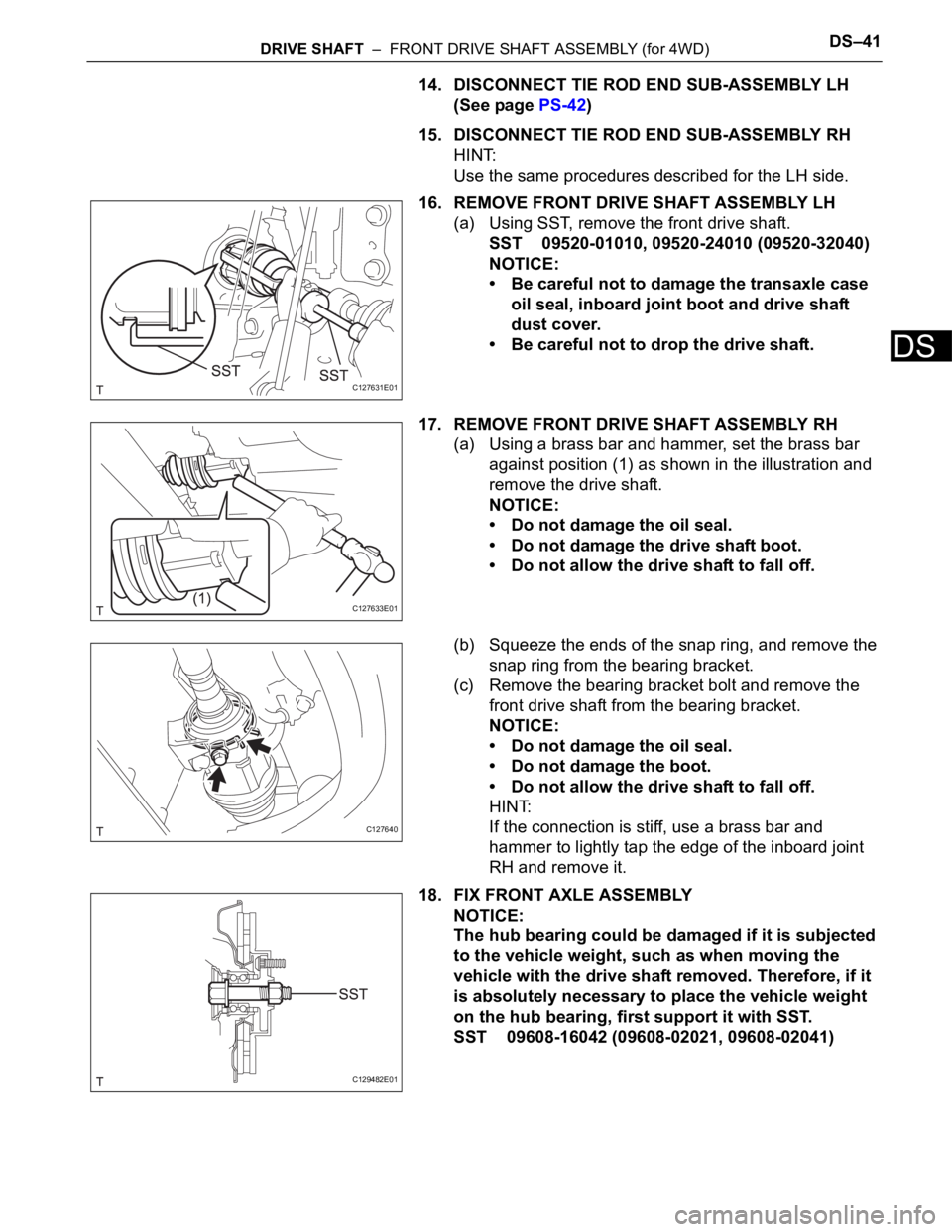
16. REMOVE FRONT DRIVE SHAFT ASSEMBLY LH
(a) Using SST, remove the front drive shaft.
SST 09520-01010, 09520-24010 (09520-32040)
NOTICE:
• Be careful not to damage the transaxle case
oil seal, inboard joint boot and drive shaft
dust cover.
• Be careful not to drop the drive shaft.
17. REMOVE FRONT DRIVE SHAFT ASSEMBLY RH
(a) Using a brass bar and hammer, set the brass bar
against position (1) as shown in the illustration and
remove the drive shaft.
NOTICE:
• Do not damage the oil seal.
• Do not damage the drive shaft boot.
• Do not allow the drive shaft to fall off.
(b) Squeeze the ends of the snap ring, and remove the
snap ring from the bearing bracket.
(c) Remove the bearing bracket bolt and remove the
front drive shaft from the bearing bracket.
NOTICE:
• Do not damage the oil seal.
• Do not damage the boot.
• Do not allow the drive shaft to fall off.
HINT:
If the connection is stiff, use a brass bar and
hammer to lightly tap the edge of the inboard joint
RH and remove it.
18. FIX FRONT AXLE ASSEMBLY
NOTICE:
The hub bearing could be damaged if it is subjected
to the vehicle weight, such as when moving the
vehicle with the drive shaft removed. Therefore, if it
is absolutely necessary to place the vehicle weight
on the hub bearing, first support it with SST.
SST 09608-16042 (09608-02021, 09608-02041)
C127631E01
C127633E01
C127640
C129482E01
Page 1396 of 2000
DS–42DRIVE SHAFT – FRONT DRIVE SHAFT ASSEMBLY (for 4WD)
DS
REMOVAL
(2006/01- )
1. REMOVE FRONT WHEEL
2. DRAIN AUTOMATIC TRANSAXLE FLUID
(a) Drain the automatic transaxle fluid for U140F (see
page AX-147).
(b) Drain the automatic transaxle fluid for U241E (see
page AX-146).
(c) Drain the automatic transaxle fluid for U151F (see
page AX-173).
3. REMOVE FRONT AXLE HUB NUT (See page AH-8)
4. DISCONNECT FRONT SPEED SENSOR LH (See page
BC-191)
5. DISCONNECT FRONT SPEED SENSOR RH
HINT:
Use the same procedures described for the LH side.
6. DISCONNECT FRONT DISC BRAKE CYLINDER
ASSEMBLY LH (See page BR-40)
7. DISCONNECT FRONT DISC BRAKE CYLINDER
ASSEMBLY RH
HINT:
Use the same procedures described for the LH side.
8. DISCONNECT FRONT STABILIZER LINK ASSEMBLY
LH (See page SP-30)
9. DISCONNECT FRONT STABILIZER LINK ASSEMBLY
RH
10. DISCONNECT FRONT SUSPENSION LOWER NO. 1
ARM SUB-ASSEMBLY LH (See page SP-22)
11. DISCONNECT FRONT SUSPENSION LOWER NO. 1
ARM SUB-ASSEMBLY RH
HINT:
Use the same procedures described for the LH side.
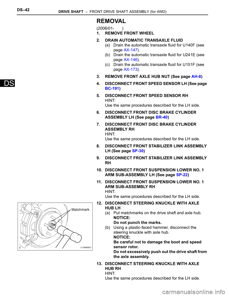
12. DISCONNECT STEERING KNUCKLE WITH AXLE
HUB LH
(a) Put matchmarks on the drive shaft and axle hub.
NOTICE:
Do not punch the marks.
(b) Using a plastic-faced hammer, disconnect the
steering knuckle with axle hub.
NOTICE:
Be careful not to damage the boot and speed
sensor rotor.
Do not excessively push out the drive shaft from
the axle assembly.
13. DISCONNECT STEERING KNUCKLE WITH AXLE
HUB RH
HINT:
Use the same procedures described for the LH side.
C129488E01
Page 1397 of 2000
DRIVE SHAFT – FRONT DRIVE SHAFT ASSEMBLY (for 4WD)DS–43
DS
14. DISCONNECT TIE ROD END SUB-ASSEMBLY LH
(See page PS-42)
15. DISCONNECT TIE ROD END SUB-ASSEMBLY RH
HINT:
Use the same procedures described for the LH side.
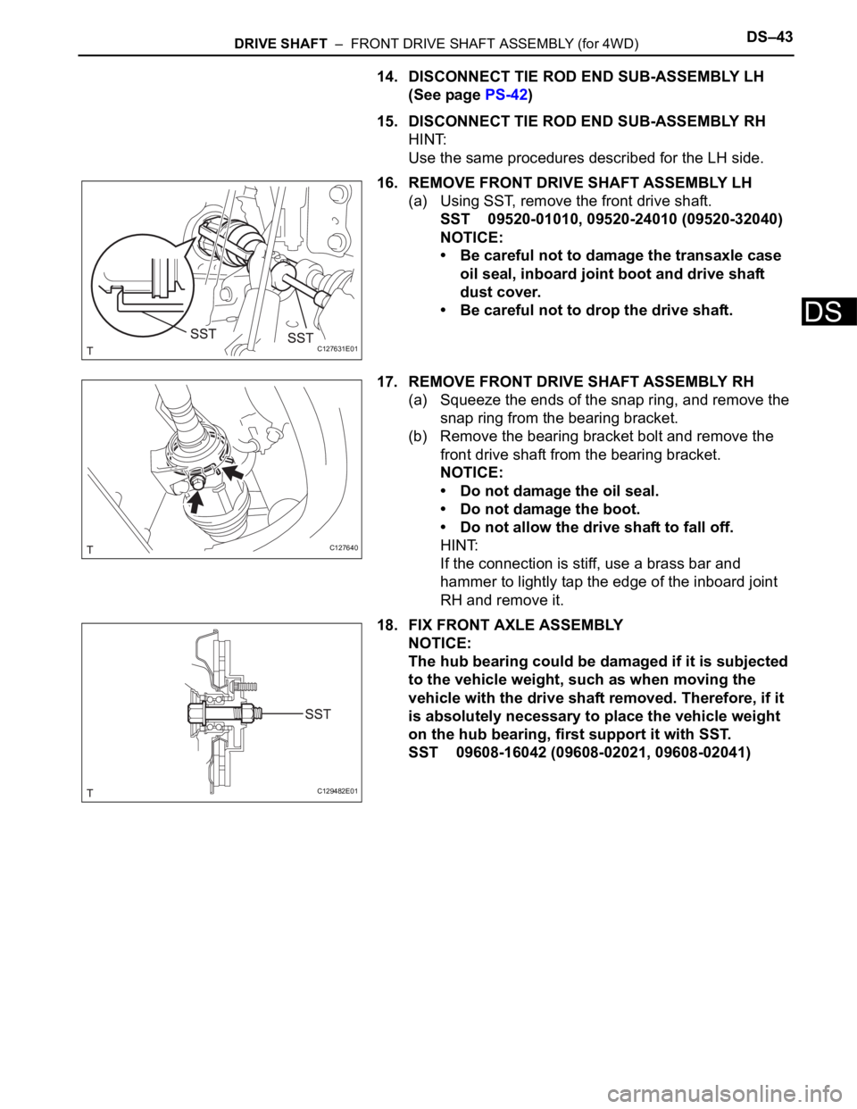
16. REMOVE FRONT DRIVE SHAFT ASSEMBLY LH
(a) Using SST, remove the front drive shaft.
SST 09520-01010, 09520-24010 (09520-32040)
NOTICE:
• Be careful not to damage the transaxle case
oil seal, inboard joint boot and drive shaft
dust cover.
• Be careful not to drop the drive shaft.
17. REMOVE FRONT DRIVE SHAFT ASSEMBLY RH
(a) Squeeze the ends of the snap ring, and remove the
snap ring from the bearing bracket.
(b) Remove the bearing bracket bolt and remove the
front drive shaft from the bearing bracket.
NOTICE:
• Do not damage the oil seal.
• Do not damage the boot.
• Do not allow the drive shaft to fall off.
HINT:
If the connection is stiff, use a brass bar and
hammer to lightly tap the edge of the inboard joint
RH and remove it.
18. FIX FRONT AXLE ASSEMBLY
NOTICE:
The hub bearing could be damaged if it is subjected
to the vehicle weight, such as when moving the
vehicle with the drive shaft removed. Therefore, if it
is absolutely necessary to place the vehicle weight
on the hub bearing, first support it with SST.
SST 09608-16042 (09608-02021, 09608-02041)
C127631E01
C127640
C129482E01
Page 1398 of 2000
DS–44DRIVE SHAFT – FRONT DRIVE SHAFT ASSEMBLY (for 4WD)
DS
DISASSEMBLY
(2005/11-2006/01)
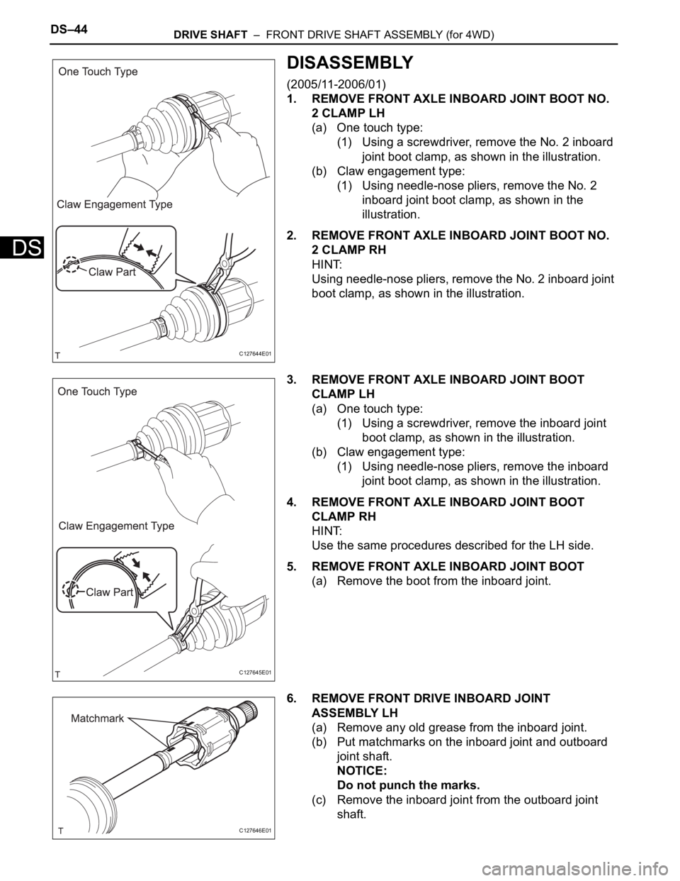
1. REMOVE FRONT AXLE INBOARD JOINT BOOT NO.
2 CLAMP LH
(a) One touch type:
(1) Using a screwdriver, remove the No. 2 inboard
joint boot clamp, as shown in the illustration.
(b) Claw engagement type:
(1) Using needle-nose pliers, remove the No. 2
inboard joint boot clamp, as shown in the
illustration.
2. REMOVE FRONT AXLE INBOARD JOINT BOOT NO.
2 CLAMP RH
HINT:
Using needle-nose pliers, remove the No. 2 inboard joint
boot clamp, as shown in the illustration.
3. REMOVE FRONT AXLE INBOARD JOINT BOOT
CLAMP LH
(a) One touch type:
(1) Using a screwdriver, remove the inboard joint
boot clamp, as shown in the illustration.
(b) Claw engagement type:
(1) Using needle-nose pliers, remove the inboard
joint boot clamp, as shown in the illustration.
4. REMOVE FRONT AXLE INBOARD JOINT BOOT
CLAMP RH
HINT:
Use the same procedures described for the LH side.
5. REMOVE FRONT AXLE INBOARD JOINT BOOT
(a) Remove the boot from the inboard joint.
6. REMOVE FRONT DRIVE INBOARD JOINT
ASSEMBLY LH
(a) Remove any old grease from the inboard joint.
(b) Put matchmarks on the inboard joint and outboard
joint shaft.
NOTICE:
Do not punch the marks.
(c) Remove the inboard joint from the outboard joint
shaft.
C127644E01
C127645E01
C127646E01
Page 1399 of 2000
DRIVE SHAFT – FRONT DRIVE SHAFT ASSEMBLY (for 4WD)DS–45
DS
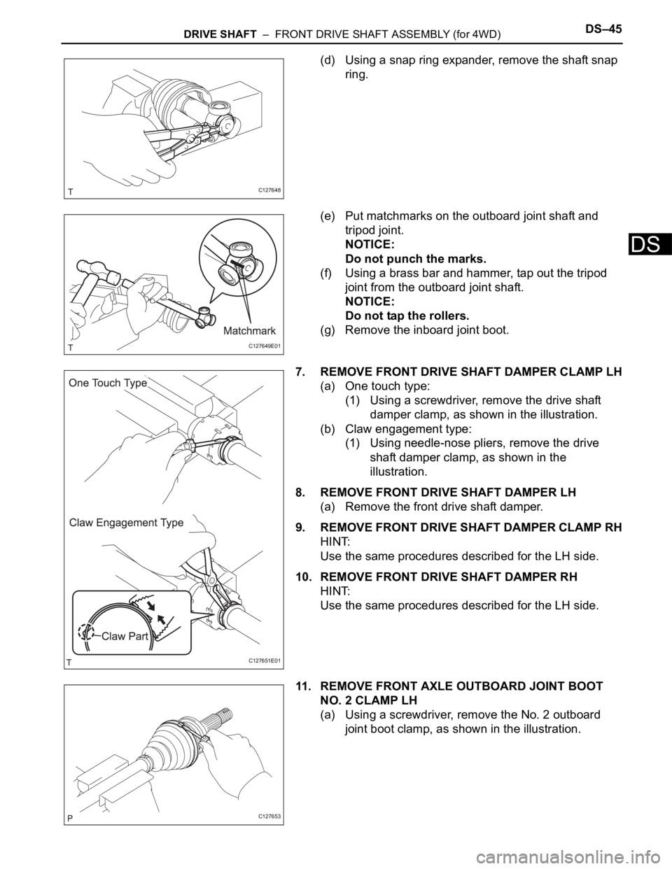
(d) Using a snap ring expander, remove the shaft snap
ring.
(e) Put matchmarks on the outboard joint shaft and
tripod joint.
NOTICE:
Do not punch the marks.
(f) Using a brass bar and hammer, tap out the tripod
joint from the outboard joint shaft.
NOTICE:
Do not tap the rollers.
(g) Remove the inboard joint boot.
7. REMOVE FRONT DRIVE SHAFT DAMPER CLAMP LH
(a) One touch type:
(1) Using a screwdriver, remove the drive shaft
damper clamp, as shown in the illustration.
(b) Claw engagement type:
(1) Using needle-nose pliers, remove the drive
shaft damper clamp, as shown in the
illustration.
8. REMOVE FRONT DRIVE SHAFT DAMPER LH
(a) Remove the front drive shaft damper.
9. REMOVE FRONT DRIVE SHAFT DAMPER CLAMP RH
HINT:
Use the same procedures described for the LH side.
10. REMOVE FRONT DRIVE SHAFT DAMPER RH
HINT:
Use the same procedures described for the LH side.
11. REMOVE FRONT AXLE OUTBOARD JOINT BOOT
NO. 2 CLAMP LH
(a) Using a screwdriver, remove the No. 2 outboard
joint boot clamp, as shown in the illustration.
C127648
C127649E01
C127651E01
C127653
Page 1400 of 2000
DS–46DRIVE SHAFT – FRONT DRIVE SHAFT ASSEMBLY (for 4WD)
DS
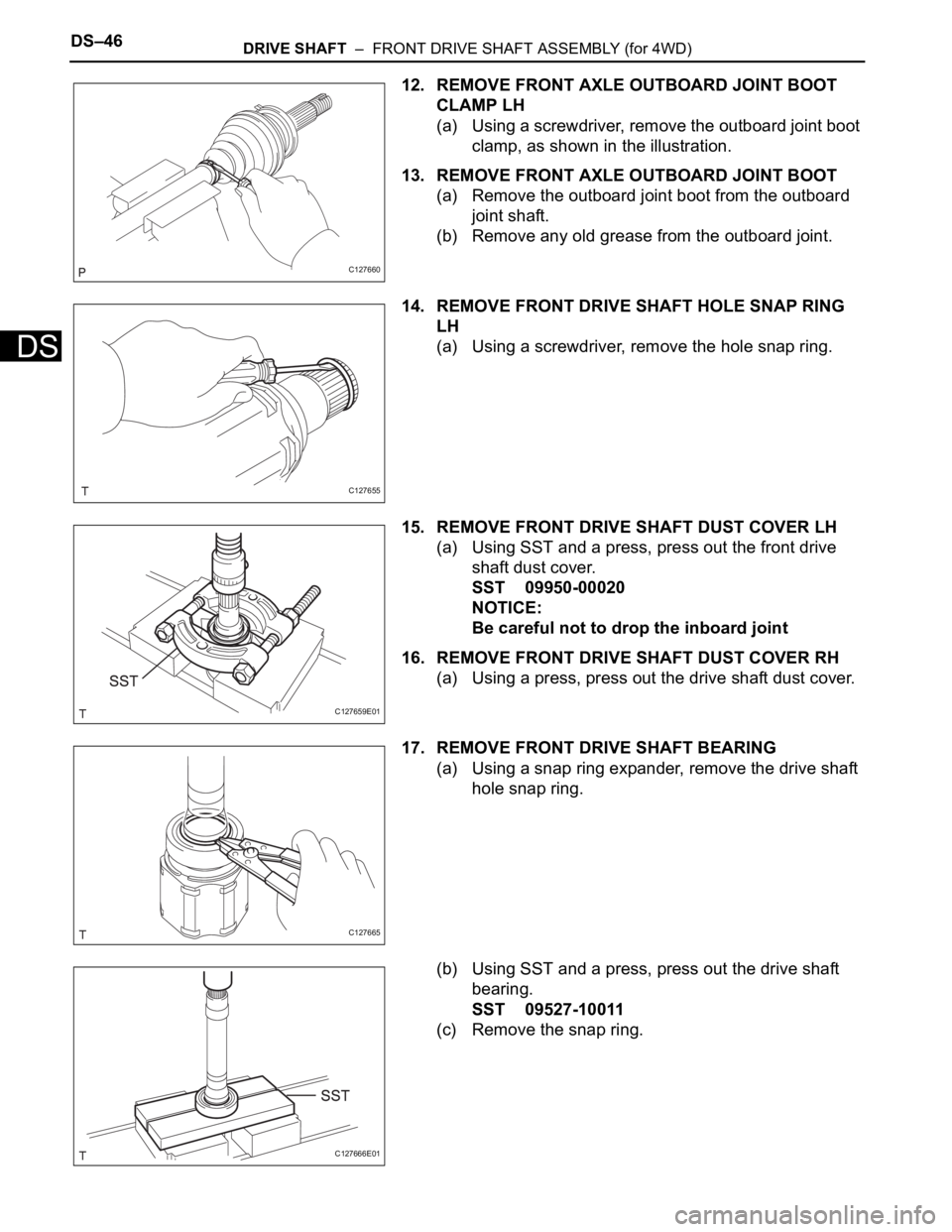
12. REMOVE FRONT AXLE OUTBOARD JOINT BOOT
CLAMP LH
(a) Using a screwdriver, remove the outboard joint boot
clamp, as shown in the illustration.
13. REMOVE FRONT AXLE OUTBOARD JOINT BOOT
(a) Remove the outboard joint boot from the outboard
joint shaft.
(b) Remove any old grease from the outboard joint.
14. REMOVE FRONT DRIVE SHAFT HOLE SNAP RING
LH
(a) Using a screwdriver, remove the hole snap ring.
15. REMOVE FRONT DRIVE SHAFT DUST COVER LH
(a) Using SST and a press, press out the front drive
shaft dust cover.
SST 09950-00020
NOTICE:
Be careful not to drop the inboard joint
16. REMOVE FRONT DRIVE SHAFT DUST COVER RH
(a) Using a press, press out the drive shaft dust cover.
17. REMOVE FRONT DRIVE SHAFT BEARING
(a) Using a snap ring expander, remove the drive shaft
hole snap ring.
(b) Using SST and a press, press out the drive shaft
bearing.
SST 09527-10011
(c) Remove the snap ring.
C127660
C127655
C127659E01
C127665
C127666E01