position sensor TOYOTA RAV4 2006 Service Repair Manual
[x] Cancel search | Manufacturer: TOYOTA, Model Year: 2006, Model line: RAV4, Model: TOYOTA RAV4 2006Pages: 2000, PDF Size: 45.84 MB
Page 1955 of 2000

2AZ-FE ENGINE CONTROL SYSTEM – SFI SYSTEMES–67
ES
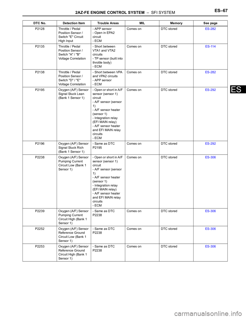
P2128 Throttle / Pedal
Position Sensor /
Switch "E" Circuit
High Input- APP sensor
- Open in EPA2
circuit
- ECMComes on DTC storedES-282
P2135 Throttle / Pedal
Position Sensor /
Switch "A" / "B"
Voltage Correlation- Short between
VTA1 and VTA2
circuits
- TP sensor (built into
throttle body)
- ECMComes on DTC storedES-114
P2138 Throttle / Pedal
Position Sensor /
Switch "D" / "E"
Voltage Correlation- Short between VPA
and VPA2 circuits
- APP sensor
- ECMComes on DTC storedES-282
P2195 Oxygen (A/F) Sensor
Signal Stuck Lean
(Bank 1 Sensor 1)- Open or short in A/F
sensor (sensor 1)
circuit
- A/F sensor (sensor
1)
- A/F sensor heater
(sensor 1)
- Integration relay
(EFI MAIN relay)
- A/F sensor heater
and EFI MAIN relay
circuits
- ECMComes on DTC storedES-292
P2196 Oxygen (A/F) Sensor
Signal Stuck Rich
(Bank 1 Sensor 1)- Same as DTC
P2195Comes on DTC storedES-292
P2238 Oxygen (A/F) Sensor
Pumping Current
Circuit Low (Bank 1
Sensor 1)- Open or short in A/F
sensor (sensor 1)
circuit
- A/F sensor (sensor
1)
- A/F sensor heater
(sensor 1)
- Integration relay
(EFI MAIN relay)
- A/F sensor heater
and EFI MAIN relay
circuits
- ECMComes on DTC storedES-306
P2239 Oxygen (A/F) Sensor
Pumping Current
Circuit High (Bank 1
Sensor 1)- Same as DTC
P2238Comes on DTC storedES-306
P2252 Oxygen (A/F) Sensor
Reference Ground
Circuit Low (Bank 1
Sensor 1)- Same as DTC
P2238Comes on DTC storedES-306
P2253 Oxygen (A/F) Sensor
Reference Ground
Circuit High (Bank 1
Sensor 1)- Same as DTC
P2238Comes on DTC storedES-306 DTC No. Detection Item Trouble Areas MIL Memory See page
Page 1957 of 2000

2AZ-FE ENGINE CONTROL SYSTEM – SFI SYSTEMES–69
ES
DESCRIPTION
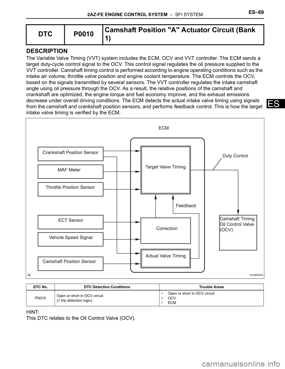
The Variable Valve Timing (VVT) system includes the ECM, OCV and VVT controller. The ECM sends a
target duty-cycle control signal to the OCV. This control signal regulates the oil pressure supplied to the
VVT controller. Camshaft timing control is performed according to engine operating conditions such as the
intake air volume, throttle valve position and engine coolant temperature. The ECM controls the OCV,
based on the signals transmitted by several sensors. The VVT controller regulates the intake camshaft
angle using oil pressure through the OCV. As a result, the relative positions of the camshaft and
crankshaft are optimized, the engine torque and fuel economy improve, and the exhaust emissions
decrease under overall driving conditions. The ECM detects the actual intake valve timing using signals
from the camshaft and crankshaft position sensors, and performs feedback control. This is how the target
intake valve timing is verified by the ECM.
HINT:
This DTC relates to the Oil Control Valve (OCV).
DTC P0010Camshaft Position "A" Actuator Circuit (Bank
1)
DTC No. DTC Detection Conditions Trouble Areas
P0010Open or short in OCV circuit
(1 trip detection logic)• Open or short in OCV circuit
•OCV
•ECM
A103843E08
Page 1961 of 2000

2AZ-FE ENGINE CONTROL SYSTEM – SFI SYSTEMES–73
ES
DESCRIPTION
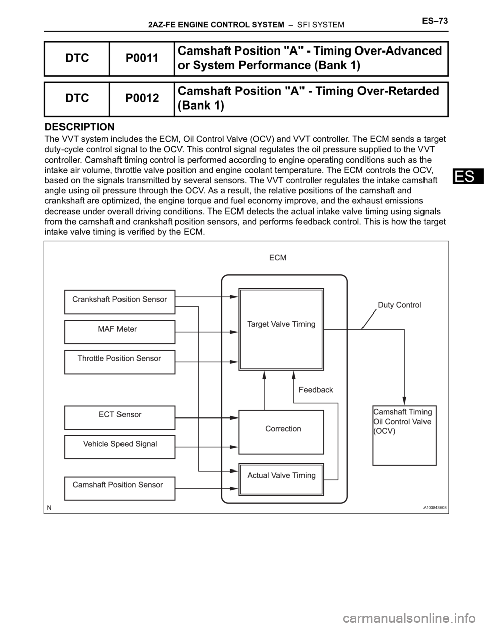
The VVT system includes the ECM, Oil Control Valve (OCV) and VVT controller. The ECM sends a target
duty-cycle control signal to the OCV. This control signal regulates the oil pressure supplied to the VVT
controller. Camshaft timing control is performed according to engine operating conditions such as the
intake air volume, throttle valve position and engine coolant temperature. The ECM controls the OCV,
based on the signals transmitted by several sensors. The VVT controller regulates the intake camshaft
angle using oil pressure through the OCV. As a result, the relative positions of the camshaft and
crankshaft are optimized, the engine torque and fuel economy improve, and the exhaust emissions
decrease under overall driving conditions. The ECM detects the actual intake valve timing using signals
from the camshaft and crankshaft position sensors, and performs feedback control. This is how the target
intake valve timing is verified by the ECM.
DTC P0011Camshaft Position "A" - Timing Over-Advanced
or System Performance (Bank 1)
DTC P0012Camshaft Position "A" - Timing Over-Retarded
(Bank 1)
A103843E08
Page 1962 of 2000

ES–742AZ-FE ENGINE CONTROL SYSTEM – SFI SYSTEM
ES
MONITOR DESCRIPTION
The ECM optimizes the intake valve timing using the VVT (Variable Valve Timing) system to control the
intake camshaft. The VVT system includes the ECM, the Oil Control Valve (OCV) and the VVT controller.
The ECM sends a target duty-cycle control signal to the OCV. This control signal regulates the oil
pressure supplied to the VVT controller. The VVT controller can advance or retard the intake camshaft.
If the difference between the target and actual intake valve timings is large, and changes in the actual
intake valve timing are small, the ECM interprets this as the VVT controller stuck malfunction and sets a
DTC.
Example:
A DTC is set when the following conditions 1, 2 and 3 are met:
1. The difference between the target and actual intake valve timing is more than 5
CA (Crankshaft
Angle) and the condition continues for more than 4.5 seconds.
2. It takes 5 seconds or more to change the valve timing by 5
CA.
3. After above conditions 1 and 2 are met, the OCV is forcibly activated 63 times or more.
DTC P0011 (Advanced Cam Timing) is subject to 1 trip detection logic.
DTC P0012 (Retarded Cam Timing) is subject to 2 trip detection logic.
These DTCs indicate that the VVT controller cannot operate properly due to OCV malfunctions or the
presence of foreign objects in the OCV.
The monitor will run if all of the following conditions are met:
– The engine is warm (the engine coolant temperature is 75
C [167F] or more).
– The vehicle has been driven at more than 64 km/h (40 mph) for 3 minutes.
– The engine has idled for 3 minutes.
MONITOR STRATEGY
DTC No. DTC Detection Conditions Trouble Areas
P0011Advanced camshaft timing:
With warm engine and engine speed of between 550 rpm and
4,000 rpm, all conditions (1), (2) and (3) met (1 trip detection
logic):
1. Difference between target and actual intake valve timings
more than 5
CA (Crankshaft Angle) for 4.5 seconds
2. Current intake valve timing fixed (timing changes less than
5
CA in 5 seconds)
3. Variations in VVT controller timing more than 19
CA of
maximum delayed timing (malfunction in advance timing)• Valve timing
•OCV
• OCV filter
• Camshaft timing gear assembly
•ECM
P0012Retarded camshaft timing:
With warm engine and engine speed of between 550 rpm and
4,000 rpm, all conditions (1), (2) and (3) met (2 trip detection
logic):
1. Difference between target and actual intake valve timings
more than 5
CA (Crankshaft Angle) for 4.5 seconds
2. Current intake valve timing fixed (timing changes less than
5
CA in 5 seconds)
3. Variations in VVT controller timing 19CA or less of
maximum delayed timing (malfunction in retarded timing)• Valve timing
•OCV
• OCV filter
• Camshaft timing gear assembly
•ECM
Related DTCsP0011: Advanced camshaft timing
P0012: Retarded camshaft timing
Required Sensors/Components (Main) VVT OCV and VVT Actuator
Required Sensors/Components (Related)Crankshaft position sensor, camshaft position sensor and Engine
coolant temperature sensor
Frequency of Operation Once per driving cycle
Duration Within 10 seconds
MIL OperationAdvanced camshaft timing: Immediate
Retarded camshaft timing: 2 driving cycles
Sequence of Operation None
Page 1963 of 2000

2AZ-FE ENGINE CONTROL SYSTEM – SFI SYSTEMES–75
ES
TYPICAL ENABLING CONDITIONS
TYPICAL MALFUNCTION THRESHOLDS
Advanced camshaft timing:
Retard camshaft timing:
If the difference between the target and actual camshaft timings is greater than the specified value, the
ECM operates the VVT actuator.
Then, the ECM monitors the camshaft timing change for 5 seconds.
WIRING DIAGRAM
Refer to DTC P0010 (see page ES-64).
INSPECTION PROCEDURE
NOTICE:
DTC P0011 or P0012 may be set when foreign objects in the engine oil are caught in some parts of
the system. The DTC will remain set even if the system returns to normal after a short time.
Foreign objects are filtered out by the oil filter.
HINT:
If DTC P0011 or P0012 is present, check the VVT (Variable Valve Timing) system.
Read freeze frame data using the intelligent tester. Freeze frame data records the engine condition when
malfunctions are detected. When troubleshooting, freeze frame data can help determine if the vehicle was
moving or stationary, if the engine was warmed up or not, if the air-fuel ratio was lean or rich, and other
data from the time the malfunction occurred.
(a) Connect the intelligent tester to the DLC3.
(b) Turn the ignition switch ON and turn the tester ON.
(c) Select the following menu items: DIAGNOSIS /
ENHANCED OBD II / DTC INFO / CURRENT CODES.
(d) Read DTCs.
Result
Monitor runs whenever following DTCs not presentP0100 - P0103 (MAF meter)
P0115 - P0118 (ECT sensor)
P0125 (Insufficient ECT for closed loop)
P0335 (CKP sensor)
P0340 (CMP sensor)
P0351 - P0354 (Igniter)
Battery voltage 11 V or more
Engine RPM 550 to 4,000 rpm
ECT 75
C (167F) to 100C (212F)
All of following conditions met -
Crank angle between reference position and actual intake camshaft
angle67
CA or more
Valve timing No change at advanced valve timing
All of following conditions met -
Crank angle between reference point and actual intake camshaft
angleLess than 67
CA
Valve timing No change at retarded valve timing
1CHECK ANY OTHER DTCS OUTPUT (IN ADDITION TO DTC P0011 OR P0012)
Display (DTC Output) Proceed To
Page 1967 of 2000

2AZ-FE ENGINE CONTROL SYSTEM – SFI SYSTEMES–79
ES
DESCRIPTION
In the VVT (Variable Valve Timing) system, the appropriate intake valve open and close timing is
controlled by the ECM. The ECM performs intake valve control by performing the following: 1) controlling
the camshaft and camshaft timing oil control valve, and operating the camshaft timing gear; and 2)
changing the relative positions of the gaps between the camshaft and crankshaft.
MONITOR DESCRIPTION
The ECM optimizes the valve timing by using the VVT (Variable Valve Timing) system to control the intake
camshaft. The VVT system includes the ECM, the Oil Control Valve (OCV) and the VVT controller.
The ECM sends a target duty-cycle control signal to the OCV. This control signal regulates the oil
pressure supplied to the VVT controller. The VVT controller can advance or retard the intake camshaft.
The ECM calibrates the intake valve timing by setting the intake camshaft to the most retarded angle while
the engine is idling. The ECM closes the OCV to retard the cam. The ECM stores this value as the VVT
learning value. When the difference between the target and actual intake valve timings is 5
CA
(Crankshaft Angle) or less, the ECM stores it.
If the VVT learning value matches the following conditions, the ECM determines the existence of a
malfunction in the VVT system, and sets the DTC.
• VVT learning value: Less than 25
CA, or more than 51CA.
• Above condition continues for 18 seconds or more.
This DTC indicates that the angle between the intake camshaft and the crankshaft is incorrect due to
factors such as the timing chain having jumped a tooth.
This monitor begins to run after the engine has idled for 5 minutes.
MONITOR STRATEGY
TYPICAL ENABLING CONDITIONS
TYPICAL MALFUNCTION THRESHOLDS
DTC P0016Crankshaft Position - Camshaft Position Corre-
lation (Bank 1 Sensor A)
DTC No. DTC Detection Conditions Trouble Areas
P0016Deviation in crankshaft and camshaft position sensor signals
(2 trip detection logic)• Mechanical system (Timing chain has jumped tooth or
chain stretched)
•ECM
Related DTCs P0016: Camshaft timing misalignment at idling
Required Sensors/Components VVT actuator
Required Sensors/Components Camshaft position sensor, Crankshaft position sensor
Frequency of Operation Once per driving cycle
Duration Within 1 minute
MIL Operation 2 driving cycles
Sequence of Operation None
Monitor runs whenever following DTCs not presentP0011 (VVT system 1 - advance)
P0012 (VVT system 1 - retarded)
P0115 - P0118 (ECT sensor)
Engine RPM 550 to 1,000 rpm
One of following conditions met -
VVT learning value when camshaft maximum retarded Less than 27.8
CA
VVT learning value when camshaft maximum retarded More than 48
CA
Page 1976 of 2000

ES–882AZ-FE ENGINE CONTROL SYSTEM – SFI SYSTEM
ES
MONITOR DESCRIPTION
The sensing position of the Heated Oxygen (HO2) sensor has a zirconia element which is used to detect
the oxygen concentration in the exhaust gas. If the zirconia element is at the appropriate temperature,
and the difference between the oxygen concentrations surrounding the inside and outside surfaces of the
sensor is large, the zirconia element generates voltage signals. In order to increase the oxygen
concentration detecting capacity of the zirconia element, the ECM supplements the heat from the exhaust
with heat from a heating element inside the sensor.
Heated oxygen sensor heater range check (P0037 and P0038):
The ECM monitors the current applied to the O2 sensor heater to check the heater for malfunctions. If the
current is below the threshold value, the ECM determines that there is an open circuit in the heater. If the
current is above the threshold value, the ECM determines that there is a short circuit in the heater.
The ECM constantly monitors the current applied to the heater. If the ECM detects an open or short
circuit, the ECM turns the MIL on and sets a DTC.
If a malfunction is detected, the ECM cuts off the current applied to the heater.
Example:
The ECM sets DTC P0038 when the current in the HO2 sensor heater is more than 2 A. Conversely,
when the heater current is less than 0.3 A, DTC P0037 is set.
Heated oxygen sensor heater performance (P0141):
After the accumulated heater ON time exceeds 100 seconds, the ECM calculates the heater resistance
using the battery voltage and the current applied to the heater.
If the resistance is above the threshold value, the ECM determines that there is a malfunction in the HO2
sensor heater and set DTC P0141.
MONITOR STRATEGY
TYPICAL ENABLING CONDITIONS
All:
P0037:
P0038:
P0141 (Heater performance monitor check):
Related DTCsP0037: Heated oxygen sensor heater range check (Low electrical
current)
P0038: Heated oxygen sensor heater range check (High electrical
current)
P0141: Heated oxygen sensor heater performance
Required Sensors/Components (Main) Heated oxygen sensor heater
Required Sensors/Components (Related) -
Frequency of OperationContinuous: P0037 and P0038
Once per driving cycle: P0141
Duration1 second: P0037 and P0038
10 seconds: P0141
MIL OperationImmediate: P0037 and P0038
2 driving cycles: P0141
Sequence of Operation None
Monitor runs whenever following DTCs not present None
Battery voltage 10.5 to 20 V
Battery voltage 10.5 to 20 V
All of following conditions met: -
Battery voltage 10.5 V or more
Fuel cut OFF
Time after fuel cut ON to OFF 30 seconds or more
Page 1981 of 2000

2AZ-FE ENGINE CONTROL SYSTEM – SFI SYSTEMES–93
ES
DESCRIPTION
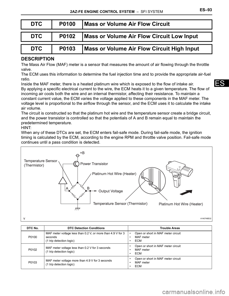
The Mass Air Flow (MAF) meter is a sensor that measures the amount of air flowing through the throttle
valve.
The ECM uses this information to determine the fuel injection time and to provide the appropriate air-fuel
ratio.
Inside the MAF meter, there is a heated platinum wire which is exposed to the flow of intake air.
By applying a specific electrical current to the wire, the ECM heats it to a given temperature. The flow of
incoming air cools both the wire and an internal thermistor, affecting their resistance. To maintain a
constant current value, the ECM varies the voltage applied to these components in the MAF meter. The
voltage level is proportional to the airflow through the sensor, and the ECM uses it to calculate the intake
air volume.
The circuit is constructed so that the platinum hot wire and the temperature sensor create a bridge circuit,
and the power transistor is controlled so that the potentials of A and B remain equal to maintain the
predetermined temperature.
HINT:
When any of these DTCs are set, the ECM enters fail-safe mode. During fail-safe mode, the ignition
timing is calculated by the ECM, according to the engine RPM and throttle valve position. Fail-safe mode
continues until a pass condition is detected.
DTC P0100 Mass or Volume Air Flow Circuit
DTC P0102 Mass or Volume Air Flow Circuit Low Input
DTC P0103 Mass or Volume Air Flow Circuit High Input
DTC No. DTC Detection Conditions Trouble Areas
P0100MAF meter voltage less than 0.2 V, or more than 4.9 V for 3
seconds
(1 trip detection logic)• Open or short in MAF meter circuit
• MAF meter
•ECM
P0102MAF meter voltage less than 0.2 V for 3 seconds
(1 trip detection logic)• Open or short in MAF meter circuit
• MAF meter
•ECM
P0103MAF meter voltage more than 4.9 V for 3 seconds
(1 trip detection logic)• Open or short in MAF meter circuit
• MAF meter
•ECM
A140749E02
Page 1982 of 2000

ES–942AZ-FE ENGINE CONTROL SYSTEM – SFI SYSTEM
ES
HINT:
When any of these DTCs are set, check the air-flow rate by selecting the following menu items on the
intelligent tester: DIAGNOSIS / ENHANCED OBD II/ DATA LIST / PRIMARY / MAF.
MONITOR DESCRIPTION
If there is a defect in the MAF meter or an open or short circuit, the voltage level deviates from the normal
operating range. The ECM interprets this deviation as a malfunction in the MAF meter and sets a DTC.
Example:
When the sensor output voltage remains less than 0.2 V, or more than 4.9 V, for more than 3 seconds, the
ECM sets a DTC.
If the malfunction is not repaired successfully, a DTC is set 3 seconds after the engine is next started.
MONITOR STRATEGY
TYPICAL ENABLING CONDITIONS
TYPICAL MALFUNCTION THRESHOLDS
P0100:
P0102:
P0103:
COMPONENT OPERATING RANGE
Mass Air Flow Rate (g/sec.) Malfunctions
Approximately 0.0• Open in Mass Air Flow (MAF) meter power source circuit
• Open or short in VG circuit
271.0 or more • Open in E2G circuit
Related DTCsP0100: MAF meter range check (Fluctuating)
P0102: MAF meter range check (Low voltage)
P0103: MAF meter range check (High voltage)
Required Sensors/Components (Main) MAF meter
Required Sensors/Components (Related) Crankshaft position sensor
Frequency of Operation Continuous
Duration 3 seconds
MIL OperationImmediate: Engine RPM less than 4,000 rpm
2 driving cycles: Engine RPM 4,000 rpm or more
Sequence of Operation None
Monitor runs whenever following DTCs not present None
MAF meter voltage Less than 0.2 V, or more than 4.9 V
MAF meter voltage Less than 0.2 V
MAF meter voltage More than 4.9 V
MAF meter voltage Between 0.4 V and 2.2 V
Page 1988 of 2000

ES–1002AZ-FE ENGINE CONTROL SYSTEM – SFI SYSTEM
ES
DESCRIPTION
Refer to DTC P0100 (see page ES-86).
MONITOR DESCRIPTION
The MAF meter is a sensor that measures the amount of air flowing through the throttle valve. The ECM
uses this information to determine the fuel injection time and to provide an appropriate air-fuel ratio. Inside
the MAF meter, there is a heated platinum wire which is exposed to the flow of intake air. By applying a
specific electrical current to the wire, the ECM heats it to a specific temperature. The flow of incoming air
cools both the wire and an internal thermistor, affecting their resistance. To maintain a constant current
value, the ECM varies the voltage applied to these components of the MAF meter. The voltage level is
proportional to the airflow through the sensor, and the ECM uses it to calculate the intake air volume.
The ECM monitors the average engine load value ratio to check the MAF meter for malfunctions. The
average engine load value ratio is obtained by comparing the average engine load calculated from the
MAF meter output to the average engine load estimated from the driving conditions, such as the engine
speed and the throttle opening angle. If the average engine load value ratio is below the threshold value,
the ECM determines that the intake air volume is low, and if the average engine load value ratio is above
the threshold value, the ECM determines that the intake air volume is high.
If this is detected in 2 consecutive driving cycles, the MIL is illuminated and a DTC is set.
MONITOR STRATEGY
TYPICAL ENABLING CONDITIONS
DTC P0101Mass Air Flow Circuit Range / Performance
Problem
DTC No. DTC Detection Conditions Trouble Areas
P0101Conditions (a), (b), (c), (d) and (e) continue for more than 10
seconds (2 trip detection logic):
(a) Engine running
(b) Engine coolant temperature 70
C (158F) or higher
(c) Throttle Position (TP) sensor voltage 0.24 V or more
(d) Average engine load value ratio less than 0.85, or more
than 1.15 (varies with estimated engine load)
Average engine load value ratio = Average engine load based
on MAF meter output / Average engine load estimated from
driving conditions
(e) Average air-fuel ratio less than -20 %, or more than 20 %• Mass Air Flow (MAF) meter
• Air induction system
• PCV hose connections
Related DTCs P0101: Mass air flow meter rationality
Required Sensors/Components (Main) Mass air flow meter
Required Sensors/Components (Related)Crankshaft Position (CKP) sensor, Engine Coolant Temperature
(ECT) sensor and Throttle Position (TP) sensor
Frequency of Operation Continuous
Duration 10 seconds
MIL Operation 2 driving cycles
Sequence of Operation None
Monitor runs whenever following DTCs not presentP0115 - P0118 (ECT sensor)
P0120 - P0223, P2135 (TP sensor)
P0125 (Insufficient ECT for closed loop)
P0335 (CKP sensor)
P0340 (CMP sensor)
Throttle position (TP sensor voltage) 0.24 V or more
Engine Running
Battery voltage 10.5 V or more