differential TOYOTA RAV4 2006 Service Workshop Manual
[x] Cancel search | Manufacturer: TOYOTA, Model Year: 2006, Model line: RAV4, Model: TOYOTA RAV4 2006Pages: 2000, PDF Size: 45.84 MB
Page 1239 of 2000
U241E AUTOMATIC TRANSAXLE – AUTOMATIC TRANSAXLE SYSTEMAX–15
AX
ROAD TEST
1. PROBLEM SYMPTOM CONFIRMATION
(a) Based on the result of the customer problem
analysis, try to reproduce the symptoms. If the
problem is that the transaxle does not shift up, shift
down, or the shift point is too high or too low,
conduct the following road test referring to the
automatic shift schedule and simulate the problem
symptoms.
2. ROAD TEST
NOTICE:
Perform the test at the normal operating ATF
temperature of 50 to 80
C (122 to 176F).
(a) D position test
Move the shift lever to D and fully depress the
accelerator pedal. Check the following:
(1) Check up-shift operation.
Check that the 1
2, 2 3 and 3 O/D up-
shifts take place at the shift point shown in the
automatic shift schedule (see page SS-60).
HINT:
O/D Gear Up-shift Prohibition Control
• Engine coolant temperature is 55
C (131F)
or less and vehicle speed is at 70 km/h (43
mph) or less.
• ATF temperature is 5
C (41F) or less.
O/D Gear Lock-up Prohibition Control
• Brake pedal is depressed.
• Accelerator pedal is released.
• Engine coolant temperature is 60
C (140F)
or less.
(2) Check for shift shock and slip.
Check for shock and slip at the 1
2, 2 3 and
3
O/D up-shifts.
(3) Check for abnormal noise and vibration.
Check for abnormal noise and vibration when
up-shifting from 1
2, 2 3 and 3 O/D while
driving with the shift lever on D, and check while
driving in the lock-up condition.
HINT:
The check for the cause of abnormal noise and
vibration must be done thoroughly as it could
also be due to loss of balance in the differential,
torque converter clutch, etc.
(4) Check kick-down operation.
While driving the vehicle in the 2nd, 3rd and O/D
gears with the shift lever on D, check that the
possible kick-down vehicle speed limits for 2
1, 3
2 and O/D 3 kick-downs conform to
those indicated in the automatic shift schedule
(see page SS-60).
(5) Check for abnormal shock and slip at kick-down.
Page 1276 of 2000
AX–172U241E AUTOMATIC TRANSAXLE – AUTOMATIC TRANSAXLE UNIT
AX
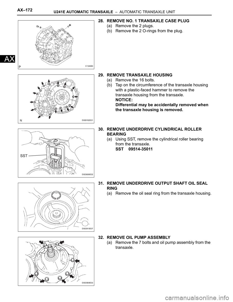
28. REMOVE NO. 1 TRANSAXLE CASE PLUG
(a) Remove the 2 plugs.
(b) Remove the 2 O-rings from the plug.
29. REMOVE TRANSAXLE HOUSING
(a) Remove the 16 bolts.
(b) Tap on the circumference of the transaxle housing
with a plastic-faced hammer to remove the
transaxle housing from the transaxle.
NOTICE:
Differential may be accidentally removed when
the transaxle housing is removed.
30. REMOVE UNDERDRIVE CYLINDRICAL ROLLER
BEARING
(a) Using SST, remove the cylindrical roller bearing
from the transaxle.
SST 09514-35011
31. REMOVE UNDERDRIVE OUTPUT SHAFT OIL SEAL
RING
(a) Remove the oil seal ring from the transaxle housing.
32. REMOVE OIL PUMP ASSEMBLY
(a) Remove the 7 bolts and oil pump assembly from the
transaxle.
C134983
D009182E01
D003606E02
D003915E07
D003569E03
Page 1277 of 2000
U241E AUTOMATIC TRANSAXLE – AUTOMATIC TRANSAXLE UNITAX–173
AX
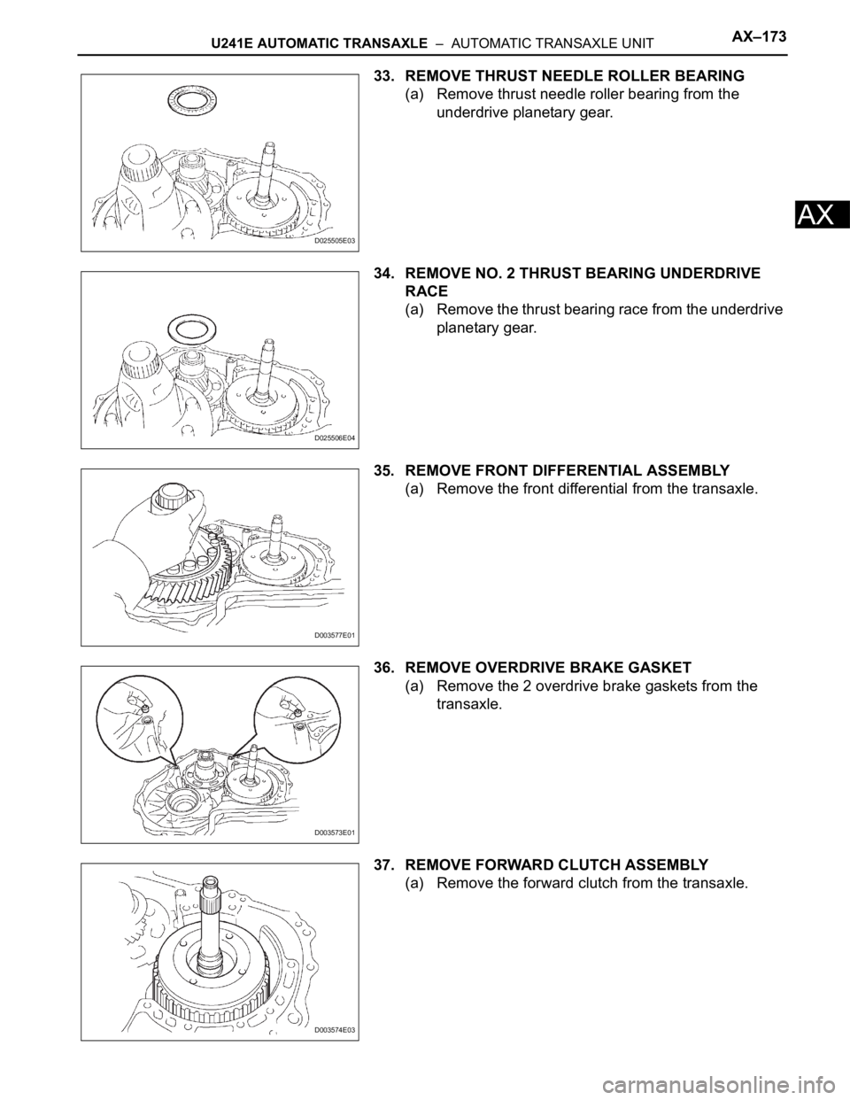
33. REMOVE THRUST NEEDLE ROLLER BEARING
(a) Remove thrust needle roller bearing from the
underdrive planetary gear.
34. REMOVE NO. 2 THRUST BEARING UNDERDRIVE
RACE
(a) Remove the thrust bearing race from the underdrive
planetary gear.
35. REMOVE FRONT DIFFERENTIAL ASSEMBLY
(a) Remove the front differential from the transaxle.
36. REMOVE OVERDRIVE BRAKE GASKET
(a) Remove the 2 overdrive brake gaskets from the
transaxle.
37. REMOVE FORWARD CLUTCH ASSEMBLY
(a) Remove the forward clutch from the transaxle.
D025505E03
D025506E04
D003577E01
D003573E01
D003574E03
Page 1289 of 2000
U241E AUTOMATIC TRANSAXLE – AUTOMATIC TRANSAXLE UNITAX–185
AX
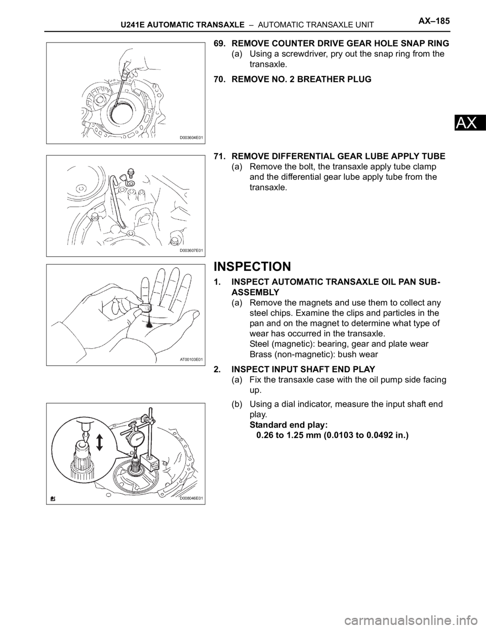
69. REMOVE COUNTER DRIVE GEAR HOLE SNAP RING
(a) Using a screwdriver, pry out the snap ring from the
transaxle.
70. REMOVE NO. 2 BREATHER PLUG
71. REMOVE DIFFERENTIAL GEAR LUBE APPLY TUBE
(a) Remove the bolt, the transaxle apply tube clamp
and the differential gear lube apply tube from the
transaxle.
INSPECTION
1. INSPECT AUTOMATIC TRANSAXLE OIL PAN SUB-
ASSEMBLY
(a) Remove the magnets and use them to collect any
steel chips. Examine the clips and particles in the
pan and on the magnet to determine what type of
wear has occurred in the transaxle.
Steel (magnetic): bearing, gear and plate wear
Brass (non-magnetic): bush wear
2. INSPECT INPUT SHAFT END PLAY
(a) Fix the transaxle case with the oil pump side facing
up.
(b) Using a dial indicator, measure the input shaft end
play.
Standard end play:
0.26 to 1.25 mm (0.0103 to 0.0492 in.)
D003604E01
D003607E01
AT00103E01
D008046E01
Page 1293 of 2000
U241E AUTOMATIC TRANSAXLE – AUTOMATIC TRANSAXLE UNITAX–189
AX
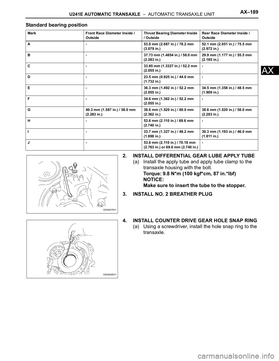
Standard bearing position
2. INSTALL DIFFERENTIAL GEAR LUBE APPLY TUBE
(a) Install the apply tube and apply tube clamp to the
transaxle housing with the bolt.
Torque: 9.8 N*m (100 kgf*cm, 87 in.*lbf)
NOTICE:
Make sure to insert the tube to the stopper.
3. INSTALL NO. 2 BREATHER PLUG
4. INSTALL COUNTER DRIVE GEAR HOLE SNAP RING
(a) Using a screwdriver, install the hole snap ring to the
transaxle.
Mark Front Race Diameter Inside /
OutsideThrust Bearing Diameter Inside
/ OutsideRear Race Diameter Inside /
Outside
A - 53.0 mm (2.087 in.) / 78.2 mm
(3.079 in.)52.1 mm (2.051 in.) / 75.5 mm
(2.972 in.)
B - 37.73 mm (1.4854 in.) / 58.0 mm
(2.283 in.)29.9 mm (1.177 in.) / 55.5 mm
(2.185 in.)
C - 33.85 mm (1.3327 in.) / 52.2 mm
(2.055 in.)-
D - 23.5 mm (0.925 in.) / 44.0 mm
(1.732 in.)-
E - 36.3 mm (1.492 in.) / 52.2 mm
(2.055 in.)34.5 mm (1.358 in.) / 48.5 mm
(1.909 in.)
F - 34.6 mm (1.362 in.) / 52.2 mm
(2.055 in.)-
G 40.3 mm (1.587 in.) / 58.0 mm
(2.283 in.)38.6 mm (1.520 in.) / 60.0 mm
(2.362 in.)38.6 mm (1.520 in.) / 58.0 mm
(2.283 in.)
H - 53.6 mm (2.110 in.) / 69.6 mm
(2.740 in.)-
I - 33.7 mm (1.327 in.) / 48.2 mm
(1.898 in.)30.3 mm (1.193 in.) / 46.0 mm
(1.811 in.)
J - 53.6 mm (2.110 in.) / 70.18 mm
(2.763 in.) or 69.6 mm (2.740 in.)-
D003607E01
D003604E01
Page 1308 of 2000
AX–204U241E AUTOMATIC TRANSAXLE – AUTOMATIC TRANSAXLE UNIT
AX
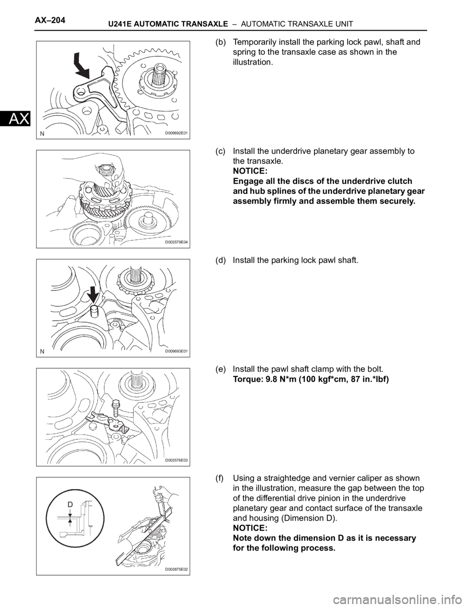
(b) Temporarily install the parking lock pawl, shaft and
spring to the transaxle case as shown in the
illustration.
(c) Install the underdrive planetary gear assembly to
the transaxle.
NOTICE:
Engage all the discs of the underdrive clutch
and hub splines of the underdrive planetary gear
assembly firmly and assemble them securely.
(d) Install the parking lock pawl shaft.
(e) Install the pawl shaft clamp with the bolt.
Torque: 9.8 N*m (100 kgf*cm, 87 in.*lbf)
(f) Using a straightedge and vernier caliper as shown
in the illustration, measure the gap between the top
of the differential drive pinion in the underdrive
planetary gear and contact surface of the transaxle
and housing (Dimension D).
NOTICE:
Note down the dimension D as it is necessary
for the following process.
D009692E01
D003579E04
D009693E01
D003576E03
D003875E02
Page 1310 of 2000
AX–206U241E AUTOMATIC TRANSAXLE – AUTOMATIC TRANSAXLE UNIT
AX
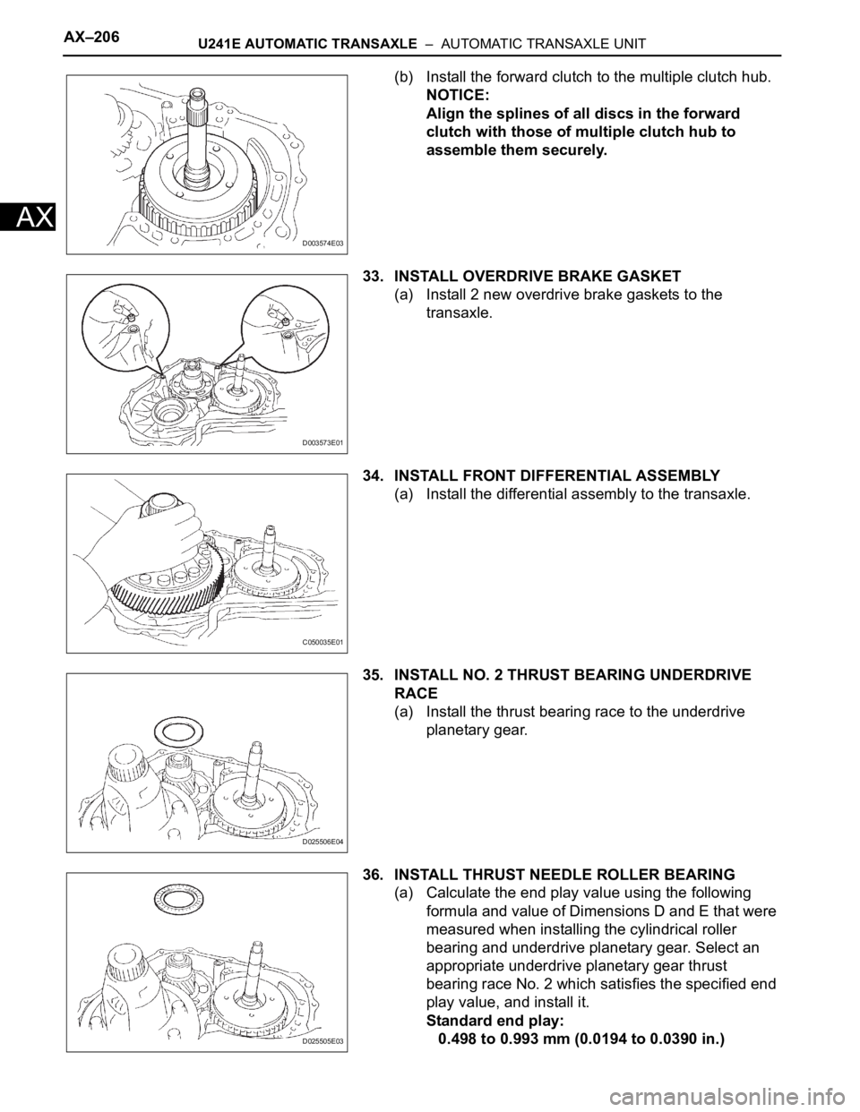
(b) Install the forward clutch to the multiple clutch hub.
NOTICE:
Align the splines of all discs in the forward
clutch with those of multiple clutch hub to
assemble them securely.
33. INSTALL OVERDRIVE BRAKE GASKET
(a) Install 2 new overdrive brake gaskets to the
transaxle.
34. INSTALL FRONT DIFFERENTIAL ASSEMBLY
(a) Install the differential assembly to the transaxle.
35. INSTALL NO. 2 THRUST BEARING UNDERDRIVE
RACE
(a) Install the thrust bearing race to the underdrive
planetary gear.
36. INSTALL THRUST NEEDLE ROLLER BEARING
(a) Calculate the end play value using the following
formula and value of Dimensions D and E that were
measured when installing the cylindrical roller
bearing and underdrive planetary gear. Select an
appropriate underdrive planetary gear thrust
bearing race No. 2 which satisfies the specified end
play value, and install it.
Standard end play:
0.498 to 0.993 mm (0.0194 to 0.0390 in.)
D003574E03
D003573E01
C050035E01
D025506E04
D025505E03
Page 1327 of 2000
U241E AUTOMATIC TRANSAXLE – DIFFERENTIAL CASEAX–257
AX
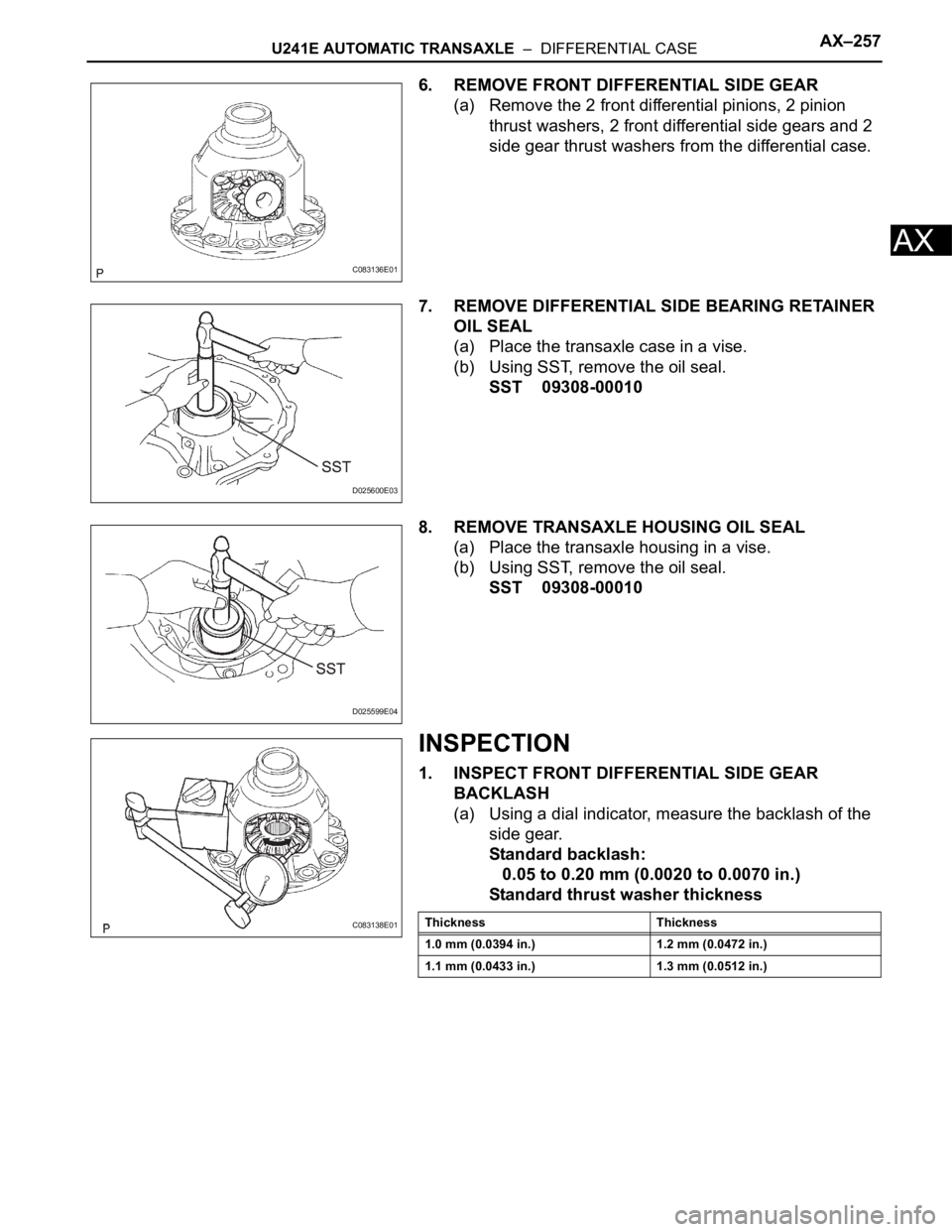
6. REMOVE FRONT DIFFERENTIAL SIDE GEAR
(a) Remove the 2 front differential pinions, 2 pinion
thrust washers, 2 front differential side gears and 2
side gear thrust washers from the differential case.
7. REMOVE DIFFERENTIAL SIDE BEARING RETAINER
OIL SEAL
(a) Place the transaxle case in a vise.
(b) Using SST, remove the oil seal.
SST 09308-00010
8. REMOVE TRANSAXLE HOUSING OIL SEAL
(a) Place the transaxle housing in a vise.
(b) Using SST, remove the oil seal.
SST 09308-00010
INSPECTION
1. INSPECT FRONT DIFFERENTIAL SIDE GEAR
BACKLASH
(a) Using a dial indicator, measure the backlash of the
side gear.
Standard backlash:
0.05 to 0.20 mm (0.0020 to 0.0070 in.)
Standard thrust washer thickness
C083136E01
D025600E03
D025599E04
C083138E01Thickness Thickness
1.0 mm (0.0394 in.) 1.2 mm (0.0472 in.)
1.1 mm (0.0433 in.) 1.3 mm (0.0512 in.)
Page 1328 of 2000
AX–258U241E AUTOMATIC TRANSAXLE – DIFFERENTIAL CASE
AX
REASSEMBLY
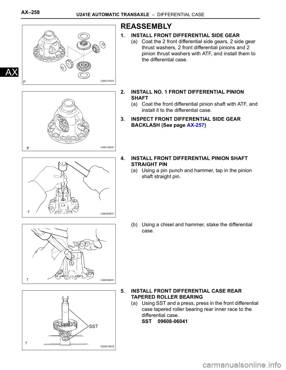
1. INSTALL FRONT DIFFERENTIAL SIDE GEAR
(a) Coat the 2 front differential side gears, 2 side gear
thrust washers, 2 front differential pinions and 2
pinion thrust washers with ATF, and install them to
the differential case.
2. INSTALL NO. 1 FRONT DIFFERENTIAL PINION
SHAFT
(a) Coat the front differential pinion shaft with ATF, and
install it to the differential case.
3. INSPECT FRONT DIFFERENTIAL SIDE GEAR
BACKLASH (See page AX-257)
4. INSTALL FRONT DIFFERENTIAL PINION SHAFT
STRAIGHT PIN
(a) Using a pin punch and hammer, tap in the pinion
shaft straight pin.
(b) Using a chisel and hammer, stake the differential
case.
5. INSTALL FRONT DIFFERENTIAL CASE REAR
TAPERED ROLLER BEARING
(a) Using SST and a press, press in the front differential
case tapered roller bearing rear inner race to the
differential case.
SST 09608-06041
C083137E01
C083135E01
C060005E01
C060006E01
D025218E03
Page 1329 of 2000
U241E AUTOMATIC TRANSAXLE – DIFFERENTIAL CASEAX–259
AX
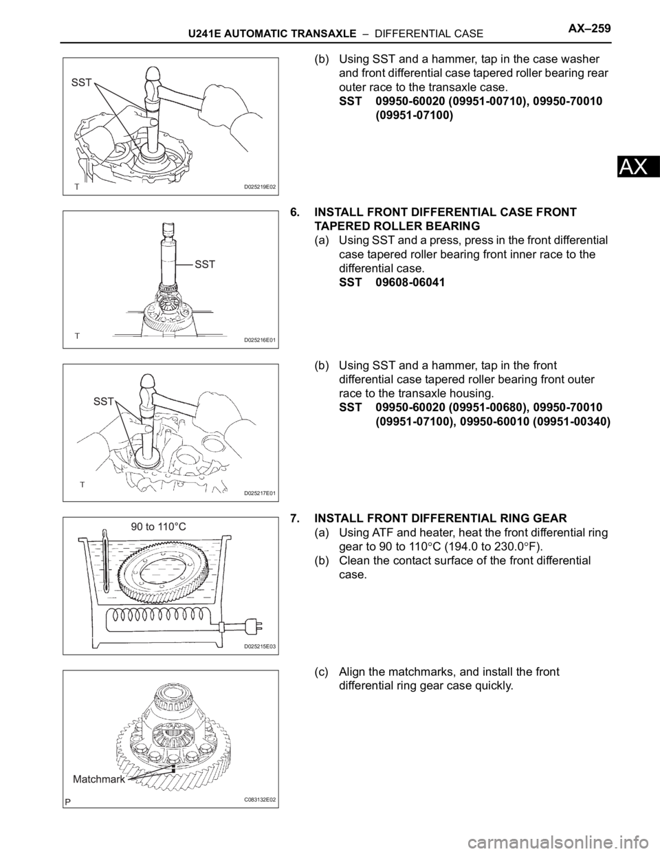
(b) Using SST and a hammer, tap in the case washer
and front differential case tapered roller bearing rear
outer race to the transaxle case.
SST 09950-60020 (09951-00710), 09950-70010
(09951-07100)
6. INSTALL FRONT DIFFERENTIAL CASE FRONT
TAPERED ROLLER BEARING
(a) Using SST and a press, press in the front differential
case tapered roller bearing front inner race to the
differential case.
SST 09608-06041
(b) Using SST and a hammer, tap in the front
differential case tapered roller bearing front outer
race to the transaxle housing.
SST 09950-60020 (09951-00680), 09950-70010
(09951-07100), 09950-60010 (09951-00340)
7. INSTALL FRONT DIFFERENTIAL RING GEAR
(a) Using ATF and heater, heat the front differential ring
gear to 90 to 110
C (194.0 to 230.0F).
(b) Clean the contact surface of the front differential
case.
(c) Align the matchmarks, and install the front
differential ring gear case quickly.
D025219E02
D025216E01
D025217E01
D025215E03
C083132E02