differential TOYOTA RAV4 2006 Service Manual PDF
[x] Cancel search | Manufacturer: TOYOTA, Model Year: 2006, Model line: RAV4, Model: TOYOTA RAV4 2006Pages: 2000, PDF Size: 45.84 MB
Page 1330 of 2000
AX–260U241E AUTOMATIC TRANSAXLE – DIFFERENTIAL CASE
AX
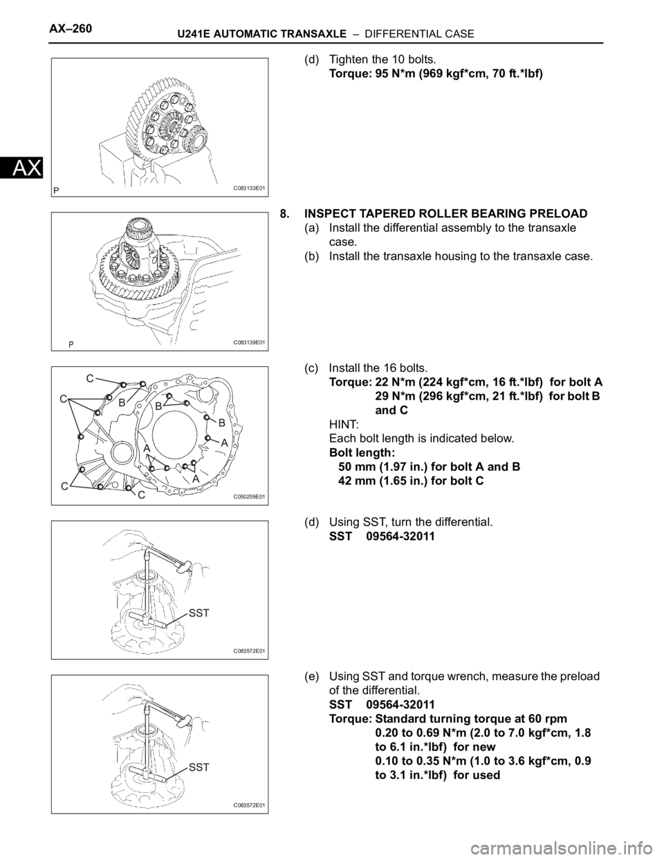
(d) Tighten the 10 bolts.
Torque: 95 N*m (969 kgf*cm, 70 ft.*lbf)
8. INSPECT TAPERED ROLLER BEARING PRELOAD
(a) Install the differential assembly to the transaxle
case.
(b) Install the transaxle housing to the transaxle case.
(c) Install the 16 bolts.
Torque: 22 N*m (224 kgf*cm, 16 ft.*lbf) for bolt A
29 N*m (296 kgf*cm, 21 ft.*lbf) for bolt B
and C
HINT:
Each bolt length is indicated below.
Bolt length:
50 mm (1.97 in.) for bolt A and B
42 mm (1.65 in.) for bolt C
(d) Using SST, turn the differential.
SST 09564-32011
(e) Using SST and torque wrench, measure the preload
of the differential.
SST 09564-32011
Torque: Standard turning torque at 60 rpm
0.20 to 0.69 N*m (2.0 to 7.0 kgf*cm, 1.8
to 6.1 in.*lbf) for new
0.10 to 0.35 N*m (1.0 to 3.6 kgf*cm, 0.9
to 3.1 in.*lbf) for used
C083133E01
C083139E01
C050259E01
C083572E01
C083572E01
Page 1331 of 2000
U241E AUTOMATIC TRANSAXLE – DIFFERENTIAL CASEAX–261
AX
Standard adjusting shim thickness
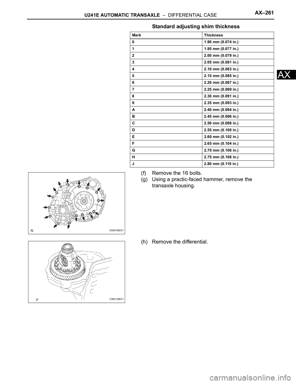
(f) Remove the 16 bolts.
(g) Using a practic-faced hammer, remove the
transaxle housing.
(h) Remove the differential.
Mark Thickness
0 1.90 mm (0.074 in.)
1 1.95 mm (0.077 in.)
2 2.00 mm (0.079 in.)
3 2.05 mm (0.081 in.)
4 2.10 mm (0.083 in.)
5 2.15 mm (0.085 in.)
6 2.20 mm (0.087 in.)
7 2.25 mm (0.089 in.)
8 2.30 mm (0.091 in.)
9 2.35 mm (0.093 in.)
A 2.40 mm (0.094 in.)
B 2.45 mm (0.096 in.)
C 2.50 mm (0.098 in.)
D 2.55 mm (0.100 in.)
E 2.60 mm (0.102 in.)
F 2.65 mm (0.104 in.)
G 2.70 mm (0.106 in.)
H 2.75 mm (0.108 in.)
J 2.80 mm (0.110 in.)
D009182E01
C083139E01
Page 1332 of 2000
AX–262U241E AUTOMATIC TRANSAXLE – DIFFERENTIAL CASE
AX
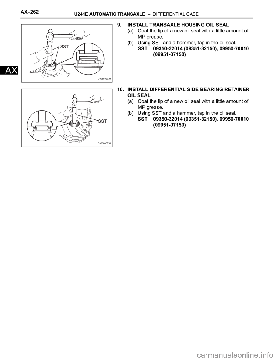
9. INSTALL TRANSAXLE HOUSING OIL SEAL
(a) Coat the lip of a new oil seal with a little amount of
MP grease.
(b) Using SST and a hammer, tap in the oil seal.
SST 09350-32014 (09351-32150), 09950-70010
(09951-07150)
10. INSTALL DIFFERENTIAL SIDE BEARING RETAINER
OIL SEAL
(a) Coat the lip of a new oil seal with a little amount of
MP grease.
(b) Using SST and a hammer, tap in the oil seal.
SST 09350-32014 (09351-32150), 09950-70010
(09951-07150)
D025606E01
D025605E01
Page 1337 of 2000
GF1A TRANSFER – ACTIVE TORQUE CONTROL 4WD SYSTEMTF–9
TF
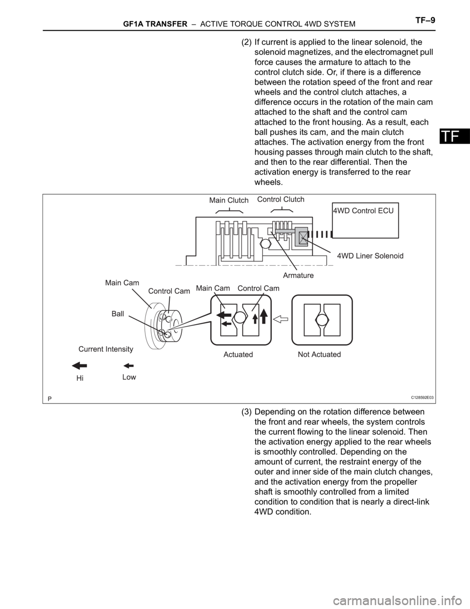
(2) If current is applied to the linear solenoid, the
solenoid magnetizes, and the electromagnet pull
force causes the armature to attach to the
control clutch side. Or, if there is a difference
between the rotation speed of the front and rear
wheels and the control clutch attaches, a
difference occurs in the rotation of the main cam
attached to the shaft and the control cam
attached to the front housing. As a result, each
ball pushes its cam, and the main clutch
attaches. The activation energy from the front
housing passes through main clutch to the shaft,
and then to the rear differential. Then the
activation energy is transferred to the rear
wheels.
(3) Depending on the rotation difference between
the front and rear wheels, the system controls
the current flowing to the linear solenoid. Then
the activation energy applied to the rear wheels
is smoothly controlled. Depending on the
amount of current, the restraint energy of the
outer and inner side of the main clutch changes,
and the activation energy from the propeller
shaft is smoothly controlled from a limited
condition to condition that is nearly a direct-link
4WD condition.
C128592E03
Page 1361 of 2000
GF1A TRANSFER – ACTIVE TORQUE CONTROL 4WD SYSTEMTF–33
TF
DESCRIPTION
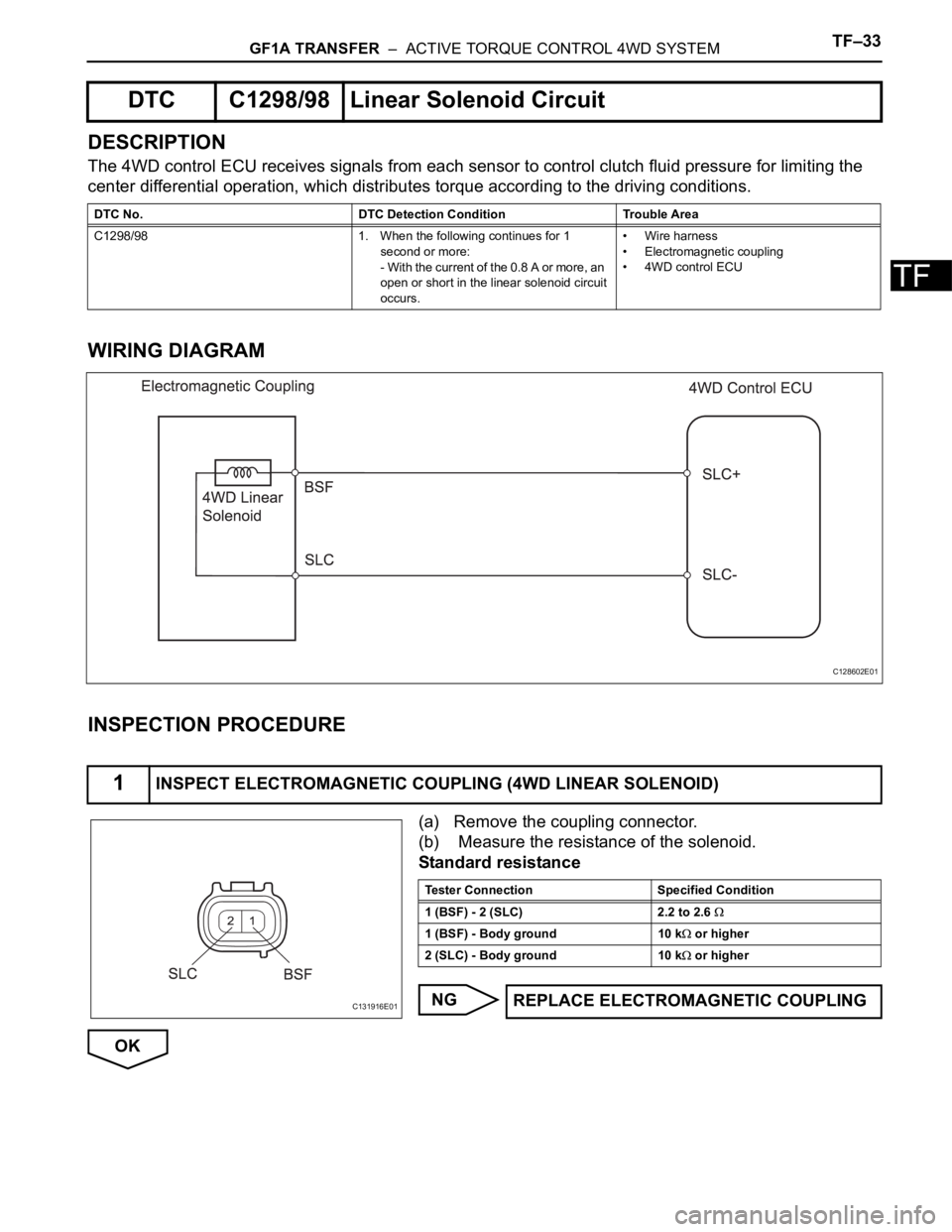
The 4WD control ECU receives signals from each sensor to control clutch fluid pressure for limiting the
center differential operation, which distributes torque according to the driving conditions.
WIRING DIAGRAM
INSPECTION PROCEDURE
(a) Remove the coupling connector.
(b) Measure the resistance of the solenoid.
Standard resistance
NG
OK
DTC C1298/98 Linear Solenoid Circuit
DTC No. DTC Detection Condition Trouble Area
C1298/98 1. When the following continues for 1
second or more:
- With the current of the 0.8 A or more, an
open or short in the linear solenoid circuit
occurs.• Wire harness
• Electromagnetic coupling
• 4WD control ECU
1INSPECT ELECTROMAGNETIC COUPLING (4WD LINEAR SOLENOID)
C128602E01
C131916E01
Tester Connection Specified Condition
1 (BSF) - 2 (SLC) 2.2 to 2.6
1 (BSF) - Body ground 10 k or higher
2 (SLC) - Body ground 10 k
or higher
REPLACE ELECTROMAGNETIC COUPLING
Page 1422 of 2000
DF–18DIFFERENTIAL – REAR DIFFERENTIAL CARRIER ASSEMBLY
DF
REMOVAL
1. DRAIN DIFFERENTIAL OIL
2. REMOVE REAR WHEEL
3. REMOVE TAILPIPE ASSEMBLY
(a) Remove the tailpipe (see page EX-2).
4. REMOVE CENTER EXHAUST PIPE ASSEMBLY
(a) Remove the center pipe (see page EX-2).
5. REMOVE PROPELLER WITH CENTER BEARING
SHAFT ASSEMBLY (See page PR-3)
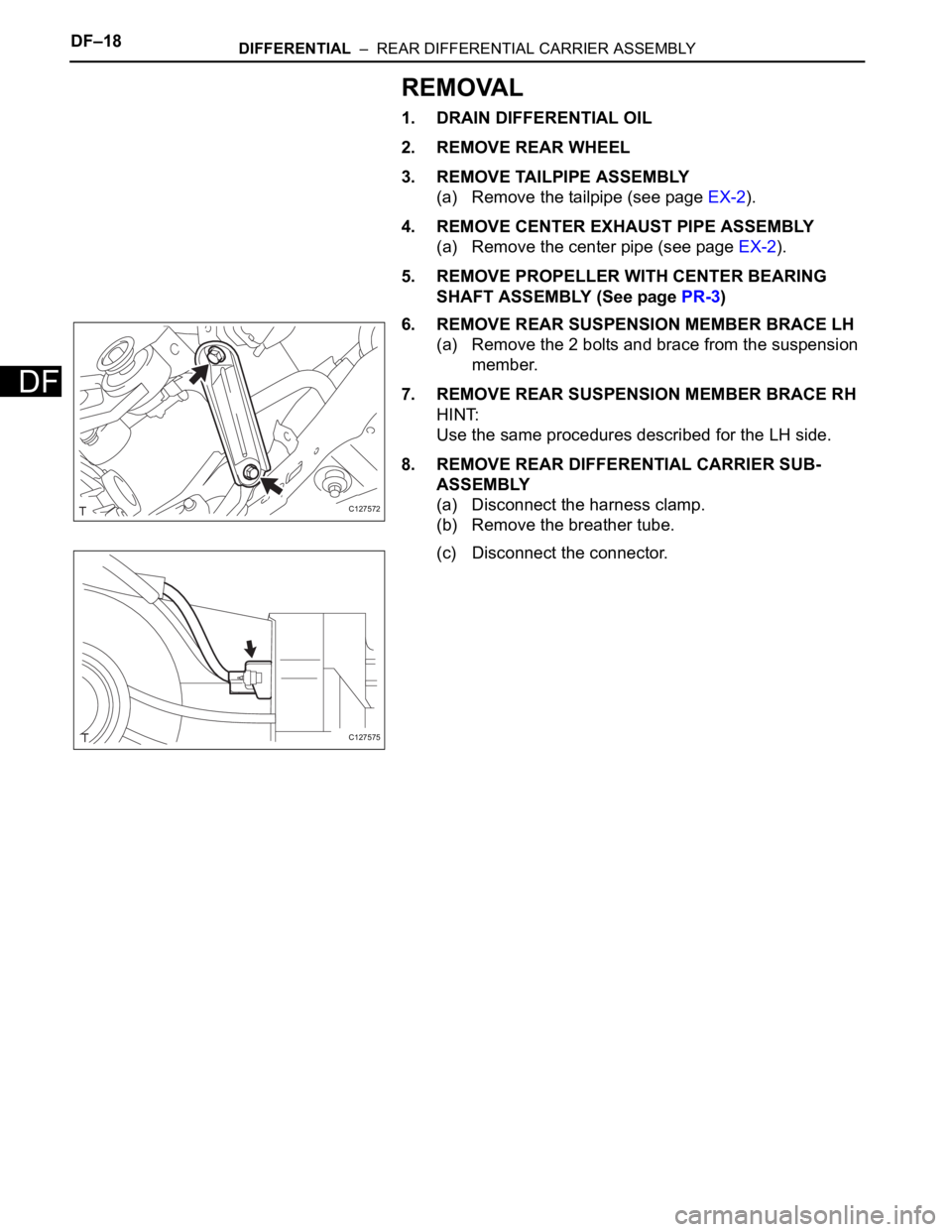
6. REMOVE REAR SUSPENSION MEMBER BRACE LH
(a) Remove the 2 bolts and brace from the suspension
member.
7. REMOVE REAR SUSPENSION MEMBER BRACE RH
HINT:
Use the same procedures described for the LH side.
8. REMOVE REAR DIFFERENTIAL CARRIER SUB-
ASSEMBLY
(a) Disconnect the harness clamp.
(b) Remove the breather tube.
(c) Disconnect the connector.
C127572
C127575
Page 1423 of 2000
DIFFERENTIAL – REAR DIFFERENTIAL CARRIER ASSEMBLYDF–19
DF
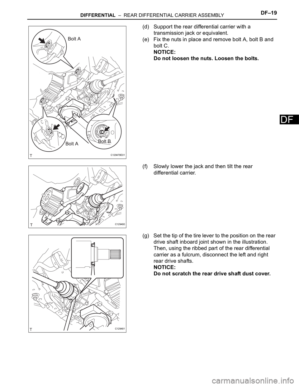
(d) Support the rear differential carrier with a
transmission jack or equivalent.
(e) Fix the nuts in place and remove bolt A, bolt B and
bolt C.
NOTICE:
Do not loosen the nuts. Loosen the bolts.
(f) Slowly lower the jack and then tilt the rear
differential carrier.
(g) Set the tip of the tire lever to the position on the rear
drive shaft inboard joint shown in the illustration.
Then, using the ribbed part of the rear differential
carrier as a fulcrum, disconnect the left and right
rear drive shafts.
NOTICE:
Do not scratch the rear drive shaft dust cover.
C129479E01
C129480
C129481
Page 1424 of 2000
DF–20DIFFERENTIAL – REAR DIFFERENTIAL CARRIER ASSEMBLY
DF
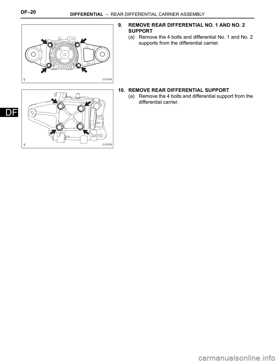
9. REMOVE REAR DIFFERENTIAL NO. 1 AND NO. 2
SUPPORT
(a) Remove the 4 bolts and differential No. 1 and No. 2
supports from the differential carrier.
10. REMOVE REAR DIFFERENTIAL SUPPORT
(a) Remove the 4 bolts and differential support from the
differential carrier.
C127578
C127579
Page 1425 of 2000
DIFFERENTIAL – REAR DIFFERENTIAL CARRIER ASSEMBLYDF–21
DF
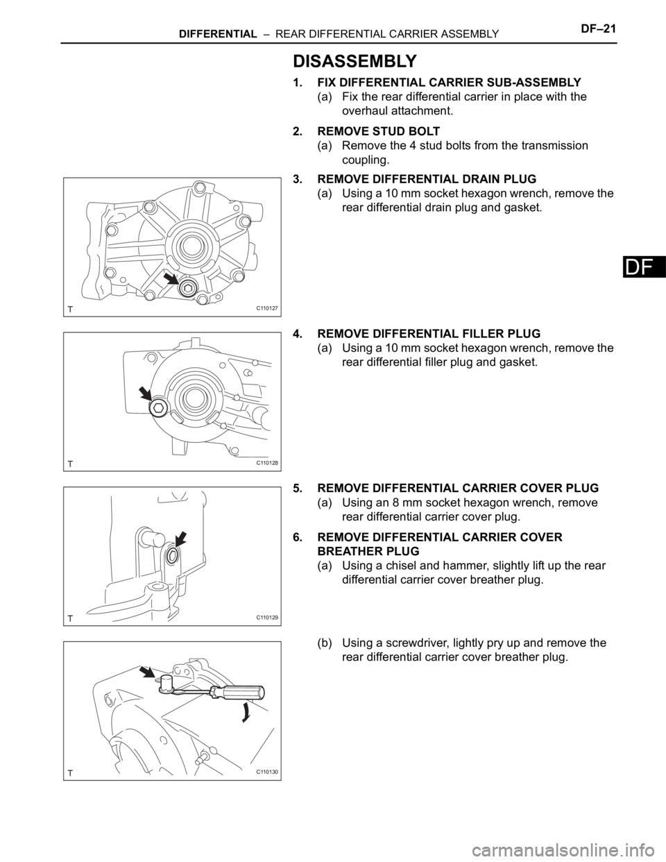
DISASSEMBLY
1. FIX DIFFERENTIAL CARRIER SUB-ASSEMBLY
(a) Fix the rear differential carrier in place with the
overhaul attachment.
2. REMOVE STUD BOLT
(a) Remove the 4 stud bolts from the transmission
coupling.
3. REMOVE DIFFERENTIAL DRAIN PLUG
(a) Using a 10 mm socket hexagon wrench, remove the
rear differential drain plug and gasket.
4. REMOVE DIFFERENTIAL FILLER PLUG
(a) Using a 10 mm socket hexagon wrench, remove the
rear differential filler plug and gasket.
5. REMOVE DIFFERENTIAL CARRIER COVER PLUG
(a) Using an 8 mm socket hexagon wrench, remove
rear differential carrier cover plug.
6. REMOVE DIFFERENTIAL CARRIER COVER
BREATHER PLUG
(a) Using a chisel and hammer, slightly lift up the rear
differential carrier cover breather plug.
(b) Using a screwdriver, lightly pry up and remove the
rear differential carrier cover breather plug.
C110127
C110128
C110129
C110130
Page 1426 of 2000
DF–22DIFFERENTIAL – REAR DIFFERENTIAL CARRIER ASSEMBLY
DF
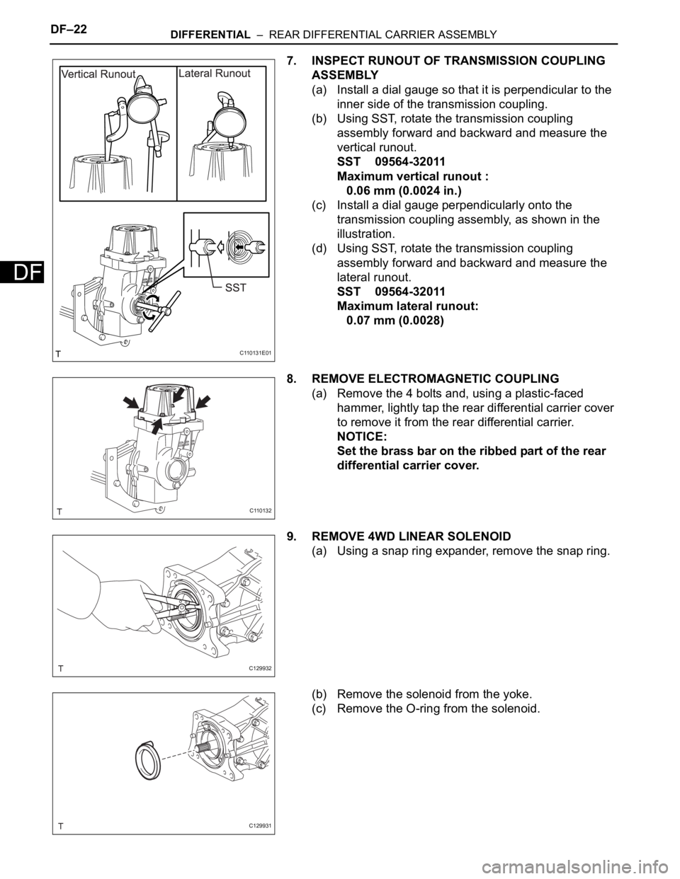
7. INSPECT RUNOUT OF TRANSMISSION COUPLING
ASSEMBLY
(a) Install a dial gauge so that it is perpendicular to the
inner side of the transmission coupling.
(b) Using SST, rotate the transmission coupling
assembly forward and backward and measure the
vertical runout.
SST 09564-32011
Maximum vertical runout :
0.06 mm (0.0024 in.)
(c) Install a dial gauge perpendicularly onto the
transmission coupling assembly, as shown in the
illustration.
(d) Using SST, rotate the transmission coupling
assembly forward and backward and measure the
lateral runout.
SST 09564-32011
Maximum lateral runout:
0.07 mm (0.0028)
8. REMOVE ELECTROMAGNETIC COUPLING
(a) Remove the 4 bolts and, using a plastic-faced
hammer, lightly tap the rear differential carrier cover
to remove it from the rear differential carrier.
NOTICE:
Set the brass bar on the ribbed part of the rear
differential carrier cover.
9. REMOVE 4WD LINEAR SOLENOID
(a) Using a snap ring expander, remove the snap ring.
(b) Remove the solenoid from the yoke.
(c) Remove the O-ring from the solenoid.
C110131E01
C110132
C129932
C129931