instrument panel TOYOTA RAV4 2006 Service Service Manual
[x] Cancel search | Manufacturer: TOYOTA, Model Year: 2006, Model line: RAV4, Model: TOYOTA RAV4 2006Pages: 2000, PDF Size: 45.84 MB
Page 1869 of 2000
LI–38LIGHTING – LIGHTING SYSTEM
LI
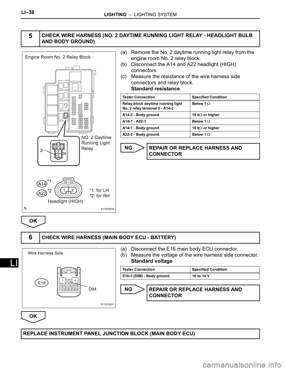
(a) Remove the No. 2 daytime running light relay from the
engine room No. 2 relay block.
(b) Disconnect the A14 and A22 headlight (HIGH)
connectors.
(c) Measure the resistance of the wire harness side
connectors and relay block.
Standard resistance
NG
OK
(a) Disconnect the E16 main body ECU connector.
(b) Measure the voltage of the wire harness side connector.
Standard voltage
NG
OK
5CHECK WIRE HARNESS (NO. 2 DAYTIME RUNNING LIGHT RELAY - HEADLIGHT BULB
AND BODY GROUND)
B118200E09
Tester Connection Specified Condition
Relay block daytime running light
No. 2 relay terminal 3 - A14-2Below 1
A14-2 - Body ground 10 k or higher
A14-1 - A22-1 Below 1
A14-1 - Body ground 10 k or higher
A22-2 - Body ground Below 1
REPAIR OR REPLACE HARNESS AND
CONNECTOR
6CHECK WIRE HARNESS (MAIN BODY ECU - BATTERY)
B118235E01
Tester Connection Specified Condition
E16-3 (DIM) - Body ground 10 to 14 V
REPAIR OR REPLACE HARNESS AND
CONNECTOR
REPLACE INSTRUMENT PANEL JUNCTION BLOCK (MAIN BODY ECU)
Page 1875 of 2000
LI–44LIGHTING – LIGHTING SYSTEM
LI
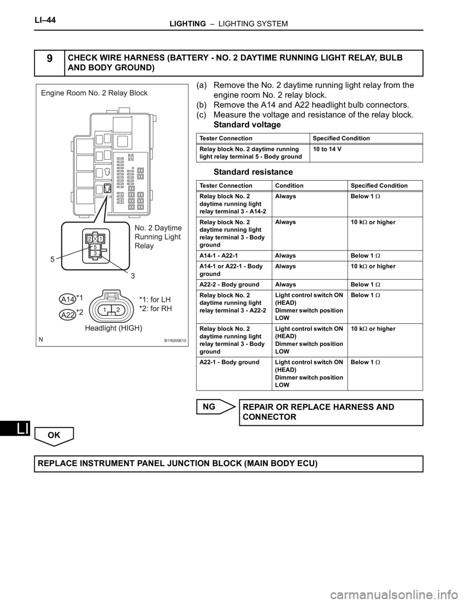
(a) Remove the No. 2 daytime running light relay from the
engine room No. 2 relay block.
(b) Remove the A14 and A22 headlight bulb connectors.
(c) Measure the voltage and resistance of the relay block.
Standard voltage
Standard resistance
NG
OK
9CHECK WIRE HARNESS (BATTERY - NO. 2 DAYTIME RUNNING LIGHT RELAY, BULB
AND BODY GROUND)
B118200E10
Tester Connection Specified Condition
Relay block No. 2 daytime running
light relay terminal 5 - Body ground10 to 14 V
Tester Connection Condition Specified Condition
Relay block No. 2
daytime running light
relay terminal 3 - A14-2Always Below 1
Relay block No. 2
daytime running light
relay terminal 3 - Body
groundAlways 10 k or higher
A14-1 - A22-1 Always Below 1
A14-1 or A22-1 - Body
groundAlways 10 k or higher
A22-2 - Body ground Always Below 1
Relay block No. 2
daytime running light
relay terminal 3 - A22-2Light control switch ON
(HEAD)
Dimmer switch position
LOWBelow 1
Relay block No. 2
daytime running light
relay terminal 3 - Body
groundLight control switch ON
(HEAD)
Dimmer switch position
LOW10 k or higher
A22-1 - Body ground Light control switch ON
(HEAD)
Dimmer switch position
LOWBelow 1
REPAIR OR REPLACE HARNESS AND
CONNECTOR
REPLACE INSTRUMENT PANEL JUNCTION BLOCK (MAIN BODY ECU)
Page 1876 of 2000

LIGHTING – LIGHTING SYSTEMLI–45
LI
(a) Disconnect the E15 main body ECU connector.
(b) Disconnect the E12 headlight dimmer switch connector.
(c) Disconnect the IJ instrument panel junction block
connector.
(d) Measure the resistance of the wire harness side
connectors.
Standard resistance
NG
OK
10CHECK WIRE HARNESS (MAIN BODY ECU - DIMMER SWITCH)
B118220E01
Tester Connection Specified Condition
E15-22 (HF) - E12-17 (HF) Below 1
E15-22 (HF) or E12-17 (HF) - Body
ground10 k or higher
IJ-4 (HU) - E12-11 (HU) Below 1
IJ-4 (HU) or E12-11 (HU) - Body
ground10 k or higher
REPAIR OR REPLACE HARNESS AND
CONNECTOR
Page 1879 of 2000

LI–48LIGHTING – LIGHTING SYSTEM
LI
(b) Turn the ignition switch to the ON position and press the
intelligent tester main switch ON.
(c) Select the item below in the ACTIVE TEST and then
check the relay operation.
Main body ECU
OK:
Front fog light comes on.
OK
NG
(a) Check that the taillight comes on when the light control
switch is on (TAIL).
OK:
Taillight comes on.
NG
OK
(a) Remove the FR FOG fuse from the instrument panel
junction block.
(b) Measure the resistance of the fuses.
Standard resistance:
Below 1
NG
OK
(a) Remove the fog light bulb.
(b) Connect the positive (+) lead from the battery to terminal
2 and the negative (-) lead to terminal 1, then check that
the bulb illuminates.
OK:
Bulb illuminates.
NG
OK
Item Test Details Diagnostic Note
F FOG LIGHT RLY Turn front fog light relay: ON / OFF -
Go to step 9
2CHECK TAILLIGHT
GO TO TAILLIGHT RELAY CIRCUIT
3INSPECT FUSE (FR FOG)
REPLACE FUSE
4INSPECT FOG LIGHT BULB
B128063E02
REPLACE FOG LIGHT BULB
Page 1881 of 2000
LI–50LIGHTING – LIGHTING SYSTEM
LI
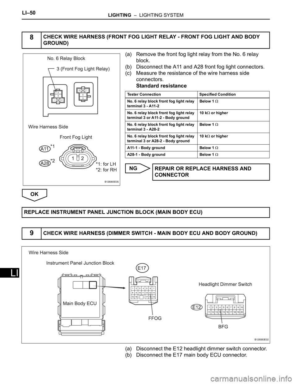
(a) Remove the front fog light relay from the No. 6 relay
block.
(b) Disconnect the A11 and A28 front fog light connectors.
(c) Measure the resistance of the wire harness side
connectors.
Standard resistance
NG
OK
(a) Disconnect the E12 headlight dimmer switch connector.
(b) Disconnect the E17 main body ECU connector.
8CHECK WIRE HARNESS (FRONT FOG LIGHT RELAY - FRONT FOG LIGHT AND BODY
GROUND)
B128065E05
Tester Connection Specified Condition
No. 6 relay block front fog light relay
terminal 3 - A11-2Below 1
No. 6 relay block front fog light relay
terminal 3 or A11-2 - Body ground10 k or higher
No. 6 relay block front fog light relay
terminal 3 - A28-2Below 1
No. 6 relay block front fog light relay
terminal 3 or A28-2 - Body ground10 k or higher
A11-1 - Body ground Below 1
A28-1 - Body ground Below 1
REPAIR OR REPLACE HARNESS AND
CONNECTOR
REPLACE INSTRUMENT PANEL JUNCTION BLOCK (MAIN BODY ECU)
9CHECK WIRE HARNESS (DIMMER SWITCH - MAIN BODY ECU AND BODY GROUND)
B128083E02
Page 1906 of 2000
DL–10DOOR LOCK – POWER DOOR LOCK CONTROL SYSTEM
DL
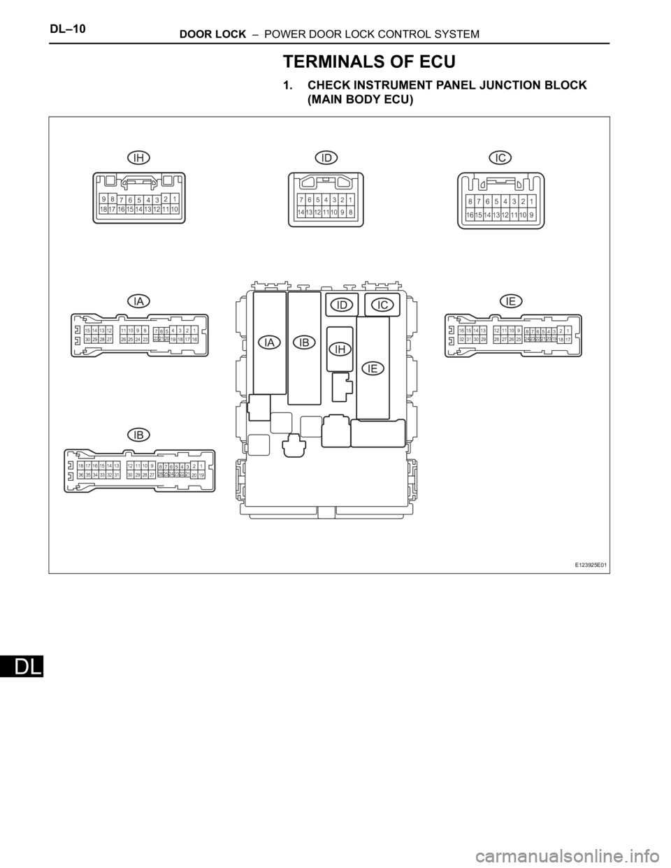
TERMINALS OF ECU
1. CHECK INSTRUMENT PANEL JUNCTION BLOCK
(MAIN BODY ECU)
E123925E01
Page 1915 of 2000

DOOR LOCK – POWER DOOR LOCK CONTROL SYSTEMDL–19
DL
Standard resistance
NG
OK
(a) All doors can be locked/unlocked at once using the
following:
• Door control switch on the master switch (switch
operation)
• Door control switch on the front passenger side
(switch operation).
• Door key cylinder linked with door lock on the driver
side (key operation)
(b) Proceed to the next step according to the symptom if all
the doors cannot be locked / unlocked at once.
B
A
(a) Proceed to the next step according to the symptom listed
in the table below.
B
C
Tester Connection Specified Condition
IE-17 (GND1) - Body ground Below 1
REPAIR OR REPLACE HARNESS AND
CONNECTOR
REPLACE INSTRUMENT PANEL JUNCTION BLOCK (MAIN BODY ECU)
4INSPECT ALL DOORS LOCK / UNLOCK OPERATION
Symptom Proceed to
All doors cannot be locked / unlocked at once using door control
switch on master switch or door key cylinder on driver sideA
All doors cannot be locked / unlocked at once using door control
switch on front passenger sideB
Go to step 12
5INSPECT DRIVER SIDE DOOR LOCK / UNLOCK OPERATION
Symptom Proceed to
All doors cannot be locked / unlocked at once using door control
switch on power window regulator master switchA
All doors cannot be locked / unlocked at once using door key cylinder
on driver sideB
All doors cannot be locked / unlocked at once using both door control
switch on master switch and door key cylinder on driver sideC
Go to step 9
REPLACE INSTRUMENT PANEL JUNCTION
BLOCK (MAIN BODY ECU)
Page 1916 of 2000

DL–20DOOR LOCK – POWER DOOR LOCK CONTROL SYSTEM
DL
A
(a) Use the DATA LIST to check if the door control switch is
functioning properly.
Main body ECU
OK:
When the switch is operating, the intelligent tester
should display as shown in the table.
OK
NG
(a) Remove the master switch.
(b) Measure the resistance of the door control switch.
Standard resistance
NG
6READ VALUE OF INTELLIGENT TESTER (DOOR CONTROL SWITCH ON MASTER
SWITCH)
Item Measurement / Display (Range) Normal Condition Diagnostic Note
D/L SW-LOCK Door manual lock switch signal /
ON or OFFON: Door control switch on power
window regulator master switch is
pushed to lock position
OFF: Door control switch on
power window regulator master
switch is not pushed-
D/L SW-UNLOCK Door manual unlock switch signal
/ ON or OFFON: Door control switch on power
window regulator master switch is
pushed to unlock position
OFF: Door control switch on
power window regulator master
switch is not pushed-
REPLACE INSTRUMENT PANEL JUNCTION
BLOCK (MAIN BODY ECU)
7INSPECT POWER WINDOW REGULATOR MASTER SWITCH ASSEMBLY (DOOR
CONTROL SWITCH)
E123893E02
Tester Connection Switch Condition Specified Condition
2 (L) - 1 (E) Lock Below 80
2 (L) - 1 (E) OFF 10 k or higher
9 (UL) -1 (E) Unlock Below 80
9 (UL) - 1 (E) OFF 10 k or higher
REPLACE POWER WINDOW REGULATOR
MASTER SWITCH ASSEMBLY
Page 1917 of 2000

DOOR LOCK – POWER DOOR LOCK CONTROL SYSTEMDL–21
DL
OK
(a) Disconnect the H2 master switch connector.
(b) Disconnect the IH junction block connector.
(c) Measure the resistance of the wire harness side
connectors.
Standard resistance
NG
OK
(a) Use the DATA LIST to check if the door key is functioning
properly.
Main body ECU
OK:
When the door key is operating, the intelligent
tester should display as shown in the table.
OK
8CHECK WIRE HARNESS (MASTER SWITCH - ECU AND BODY GROUND)
E123901E02
Tester Connection Specified Condition
H2-2 (L) - IH-4 (L1) Below 1
H2-2 (L) - Body ground 10 k or higher
IH-4 (L1) - Body ground 10 k
or higher
H2-9 (UL) -IH-5 (UL1) Below 1
H2-9 (UL) - Body ground 10 k or higher
IH-5 (UL1) - Body ground 10 k
or higher
H2-1 (E) - Body ground Below 1
REPAIR OR REPLACE HARNESS AND
CONNECTOR
REPLACE INSTRUMENT PANEL JUNCTION BLOCK (MAIN BODY ECU)
9READ VALUE OF INTELLIGENT TESTER (DOOR KEY SWITCH)
Item Measurement / Display (Range) Normal Condition Diagnostic Note
DOR KEY SW-LOCK Door key linked lock switch signal
/ ON or OFFON: Driver side door key cylinder
is turned to lock position
OFF: Driver side door key
cylinder is not turned-
D DOR KEY SW-UL Door key linked lock switch signal
/ ON or OFFON: Driver side door key cylinder
is turned to unlock position
OFF: Driver side door key
cylinder is not turned-
REPLACE INSTRUMENT PANEL JUNCTION
BLOCK (MAIN BODY ECU)
Page 1919 of 2000

DOOR LOCK – POWER DOOR LOCK CONTROL SYSTEMDL–23
DL
Standard resistance
NG
OK
(a) Remove the control switch.
(b) Measure the resistance of the door control switch.
Standard resistance
NG
OK
Tester Connection Specified Condition
H5-9 (L) - IH-7 (L2) Below 1
H5-9 (L) - Body ground 10 k or higher
IH-7 (L2) - Body ground 10 k
or higher
H5-10 (UL) - E15-9 (UL3) Below 1
H5-10 (UL) - Body ground 10 k or higher
E15-9 (UL3) - Body ground 10 k
or higher
REPAIR OR REPLACE HARNESS AND
CONNECTOR
REPLACE INSTRUMENT PANEL JUNCTION BLOCK (MAIN BODY ECU)
12INSPECT DOOR CONTROL SWITCH ASSEMBLY
E123894E01
Tester Connection Switch Condition Specified Condition
4 (L) - 3 (E) Lock Below 200
4 (L) - 3 (E) OFF 10 k or higher
2 (UL) - 3 (E) Unlock Below 200
2 (UL) - 3 (E) OFF 10 k or higher
REPLACE DOOR CONTROL SWITCH
ASSEMBLY