position sensor TOYOTA RAV4 2006 Service Manual PDF
[x] Cancel search | Manufacturer: TOYOTA, Model Year: 2006, Model line: RAV4, Model: TOYOTA RAV4 2006Pages: 2000, PDF Size: 45.84 MB
Page 560 of 2000

ES–362GR-FE ENGINE CONTROL SYSTEM – SFI SYSTEM
ES
VV2+ (B30-67) - VV2- (B30-90) W - B Variable valve timing
(VVT) sensor (Intake side
(bank 2))Idling Pulse generation
(see waveform 5)
EV1+ (B30-68) - EV1- (B30-91) Y - G Variable valve timing
(VVT) sensor (Exhaust
side (bank 1))Idling Pulse generation
(see waveform 5)
EV2+ (B30-66) - EV2- (B30-89) R - L Variable valve timing
(VVT) sensor (Exhaust
side (bank 2))Idling Pulse generation
(see waveform 5)
NE+ (B30-110) - NE- (B30-111) G - R Crankshaft position sensor Idling Pulse generation (see
waveform 5)
IGT1 (B30-40) - E1 (B30-81)
IGT2 (B30-39) - E1 (B30-81)
IGT3 (B30-38) - E1 (B30-81)
IGT4 (B30-37) - E1 (B30-81)
IGT5 (B30-36) - E1 (B30-81)
IGT6 (B30-35) - E1 (B30-81)W - BR
G-R - BR
G - BR
LG - BR
P - BR
V - BRIgnition coil (ignition
signal)Idling Pulse generation (see
waveform 6)
IGF1 (B30-106) - E1 (B30-81) Y - BR Ignition coil (ignition
confirmation signal)Ignition switch ON 4.5 to 5.5 V
Idling Pulse generation (see
waveform 6)
PRG (B30-108) - E1 (B30-81) LG - BR Purge VSV Ignition switch ON 9 to 14 V
Idling Pulse generation (see
waveform 7)
SPD (A9-8) - E1 (B30-81) V - BR Speed signal from
combination meterDriving at 20 km/h (12 mph) Pulse generation (see
waveform 8)
STA (A9-48) - E1 (B30-81) LG - BR Starter signal Cranking 5.5 V or more
NSW (B30-62) - E1 (B30-81) G-R - BR Starter relay control Ignition switch ON Below 1.5 V
Cranking 6.0 V or more
STP (A9-36) - E1 (B30-81) L - BR Stop light switch Brake pedal depressed 7.5 to 14 V
Brake pedal released Below 1.5 V
ST1- (A9-35) - E1 (B30-81) GR - BR Stop light switch
(opposite to STP terminal)Ignition switch ON,
Brake pedal depressedBelow 1.5 V
Ignition switch ON,
Brake pedal released7.5 to 14 V
M+ (B30-19) - ME01 (B30-20) G - BR Throttle actuator Idling with warm engine Pulse generation (see
waveform 9)
M- (B30-18) - ME01 (B30-20) R - BR Throttle actuator Idling with warm engine Pulse generation (see
waveform 10)
FC (A9-7) - E1 (B30-81) W - BR Fuel pump control Ignition switch ON 9 to 14 V
Idling Below 1.5 V
FPR (B30-59) - E1 (B30-81) W - BR Fuel pump control Cranking 9 to 14 V
FPR (B30-59) - E1 (B30-81) W - BR Fuel pump control Idling 9 to 14 V
W (A9-24) - E1 (B30-81) R - BR MIL Ignition switch ON Below 1.5 V
Idling 9 to 14 V
TC (A9-27) - E1 (B30-81) G - BR Terminal TC of DLC3 Ignition switch ON 9 to 14 V
TACH (A9-15) - E1 (B30-81) GR - BR Engine speed Idling Pulse generation (see
waveform 11)
VPMP (A9-42) - E1 (B30-81) W - BR Vent valve (built into
canister pump module)Ignition switch ON 9 to 14 V
MPMP (A9-34) - E1 (B30-81) B - BR Leak detection pump (built
into canister pump
module)Leak detection pump OFF Below 3 V
Leak detection pump ON 9 to 14 V
VCPP (B30-75) - EPPM (B30-76) V - BR Power source for canister
pressure sensor (specific
voltage)Ignition switch ON 4.5 to 5.5 V Symbol (Terminal No.) Wiring Color Terminal Description Condition Specified Condition
Page 562 of 2000
ES–382GR-FE ENGINE CONTROL SYSTEM – SFI SYSTEM
ES
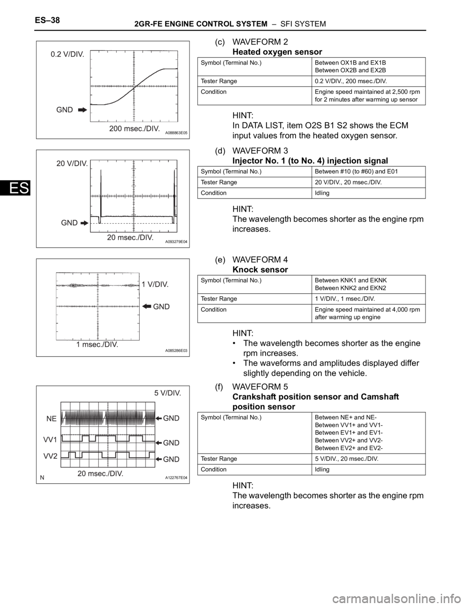
(c) WAVEFORM 2
Heated oxygen sensor
HINT:
In DATA LIST, item O2S B1 S2 shows the ECM
input values from the heated oxygen sensor.
(d) WAVEFORM 3
Injector No. 1 (to No. 4) injection signal
HINT:
The wavelength becomes shorter as the engine rpm
increases.
(e) WAVEFORM 4
Knock sensor
HINT:
• The wavelength becomes shorter as the engine
rpm increases.
• The waveforms and amplitudes displayed differ
slightly depending on the vehicle.
(f) WAVEFORM 5
Crankshaft position sensor and Camshaft
position sensor
HINT:
The wavelength becomes shorter as the engine rpm
increases.
A088863E05
Symbol (Terminal No.) Between OX1B and EX1B
Between OX2B and EX2B
Tester Range 0.2 V/DIV., 200 msec./DIV.
Condition Engine speed maintained at 2,500 rpm
for 2 minutes after warming up sensor
A093279E04
Symbol (Terminal No.) Between #10 (to #60) and E01
Tester Range 20 V/DIV., 20 msec./DIV.
Condition Idling
A085286E03
Symbol (Terminal No.) Between KNK1 and EKNK
Between KNK2 and EKN2
Tester Range 1 V/DIV., 1 msec./DIV.
Condition Engine speed maintained at 4,000 rpm
after warming up engine
A122767E04
Symbol (Terminal No.) Between NE+ and NE-
Between VV1+ and VV1-
Between EV1+ and EV1-
Between VV2+ and VV2-
Between EV2+ and EV2-
Tester Range 5 V/DIV., 20 msec./DIV.
Condition Idling
Page 571 of 2000

2GR-FE ENGINE CONTROL SYSTEM – SFI SYSTEMES–47
ES
KNOCK FB VAL Feedback value of knocking -
ACCEL POS #1Absolute Accelerator Pedal Position (APP)
No.1-
ACCEL POS #2 Absolute APP No. 2 -
THROTTLE POS Throttle sensor positioning -
THROTTLE POS Throttle position -
THROTTLE POS #2 Throttle sensor positioning #2 -
THROTTLE MOT Throttle motor -
O2S B1 S2
O2S B2 S2Heated oxygen sensor outputPerforming INJ VOL or A/F CONTROL
function of ACTIVE TEST enables technician
to check output voltage of sensor
AFS B1 S1
AFS B2 S1A/F sensor outputPerforming INJ VOL or A/F CONTROL
function of ACTIVE TEST enables technician
to check output voltage of sensor
TOTAL FT #1
TOTAL FT #2Total fuel trim -
SHORT FT #1
SHORT FT #2Short-term fuel trimShort-term fuel compensation used to
maintain air-fuel ratio at stoichiometric air-fuel
ratio
LONG FT #1
LONG FT #2Long-term fuel trimOverall fuel compensation carried out in long-
term to compensate a continual deviation of
short-term fuel trim from central valve
O2FT B1 S2
O2FT B2 S2Fuel trim at heated oxygen sensor -
AF FT B1 S1
AF FT B2 S1Fuel trim at A/F sensor-
AFS B1 S1
AFS B2 S1A/F sensor current-
CAT TEMP B1S1
CAT TEMP B2S1Estimated catalyst temperature (sensor 1)-
CAT TEMP B1S2
CAT TEMP B2S2Estimated catalyst temperature (sensor 2)-
S O2S B1S2
S O2S B2S2Sub heated oxygen sensor impedance
(sensor 2)-
INI COOL TEMP Engine coolant temperature at engine start -
INI INTAKE TEMP Intake air temperature at engine start -
INJ VOL Injection volume -
STARTER SIG Starter switch (STSW) signal -
PS SW Power steering signal -
PS SIGNAL Power steering signal (history)Signal status usually ON until ignition switch
turned OFF
CTP SW Closed throttle position switch -
A/C SIGNAL A/C signal -
PNP SW (NSW) Park/Neutral Position (PNP) switch signal -
ELECT LOAD SIG Electrical load signal -
STOP LIGHT SW Stop light switch -
BATTERY VOLTAGE Battery voltage -
ATM PRESSURE Atmosphere pressure -
FUEL PMP SP CTL Fuel pump speed control status -
ACIS VSVVSV for Acoustic Control Induction System
(ACIS)-
EVAP (Purge) VSV EVAP Purge VSV -
FUEL PUMP/SPD Fuel pump/speed status -LABEL
(Intelligent Tester Display)Measurement Item Diagnostic Note
Page 573 of 2000
ES–4742GR-FE ENGINE CONTROL SYSTEM – ACCELERATOR PEDAL ROD
ES
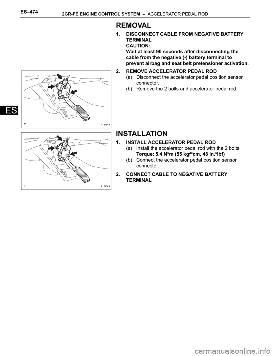
REMOVAL
1. DISCONNECT CABLE FROM NEGATIVE BATTERY
TERMINAL
CAUTION:
Wait at least 90 seconds after disconnecting the
cable from the negative (-) battery terminal to
prevent airbag and seat belt pretensioner activation.
2. REMOVE ACCELERATOR PEDAL ROD
(a) Disconnect the accelerator pedal position sensor
connector.
(b) Remove the 2 bolts and accelerator pedal rod.
INSTALLATION
1. INSTALL ACCELERATOR PEDAL ROD
(a) Install the accelerator pedal rod with the 2 bolts.
Torque: 5.4 N*m (55 kgf*cm, 48 in.*lbf)
(b) Connect the accelerator pedal position sensor
connector.
2. CONNECT CABLE TO NEGATIVE BATTERY
TERMINAL
A124549
A124549
Page 583 of 2000
EM–262AZ-FE ENGINE MECHANICAL – TIMING CHAIN
EM
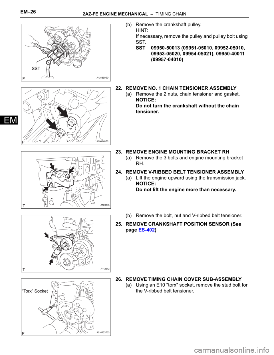
(b) Remove the crankshaft pulley.
HINT:
If necessary, remove the pulley and pulley bolt using
SST.
SST 09950-50013 (09951-05010, 09952-05010,
09953-05020, 09954-05021), 09950-40011
(09957-04010)
22. REMOVE NO. 1 CHAIN TENSIONER ASSEMBLY
(a) Remove the 2 nuts, chain tensioner and gasket.
NOTICE:
Do not turn the crankshaft without the chain
tensioner.
23. REMOVE ENGINE MOUNTING BRACKET RH
(a) Remove the 3 bolts and engine mounting bracket
RH.
24. REMOVE V-RIBBED BELT TENSIONER ASSEMBLY
(a) Lift the engine upward using the transmission jack.
NOTICE:
Do not lift the engine more than necessary.
(b) Remove the bolt, nut and V-ribbed belt tensioner.
25. REMOVE CRANKSHAFT POSITION SENSOR (See
page ES-402)
26. REMOVE TIMING CHAIN COVER SUB-ASSEMBLY
(a) Using an E10 "torx" socket, remove the stud bolt for
the V-ribbed belt tensioner.
A124860E01
A098348E01
A128165
A112212
A014253E03
Page 584 of 2000
2AZ-FE ENGINE MECHANICAL – TIMING CHAINEM–27
EM
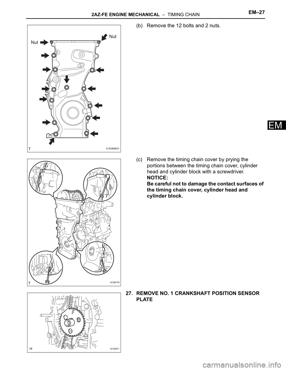
(b) Remove the 12 bolts and 2 nuts.
(c) Remove the timing chain cover by prying the
portions between the timing chain cover, cylinder
head and cylinder block with a screwdriver.
NOTICE:
Be careful not to damage the contact surfaces of
the timing chain cover, cylinder head and
cylinder block.
27. REMOVE NO. 1 CRANKSHAFT POSITION SENSOR
PLATE
A132568E01
A128179
A132571
Page 592 of 2000
2AZ-FE ENGINE MECHANICAL – TIMING CHAINEM–35
EM
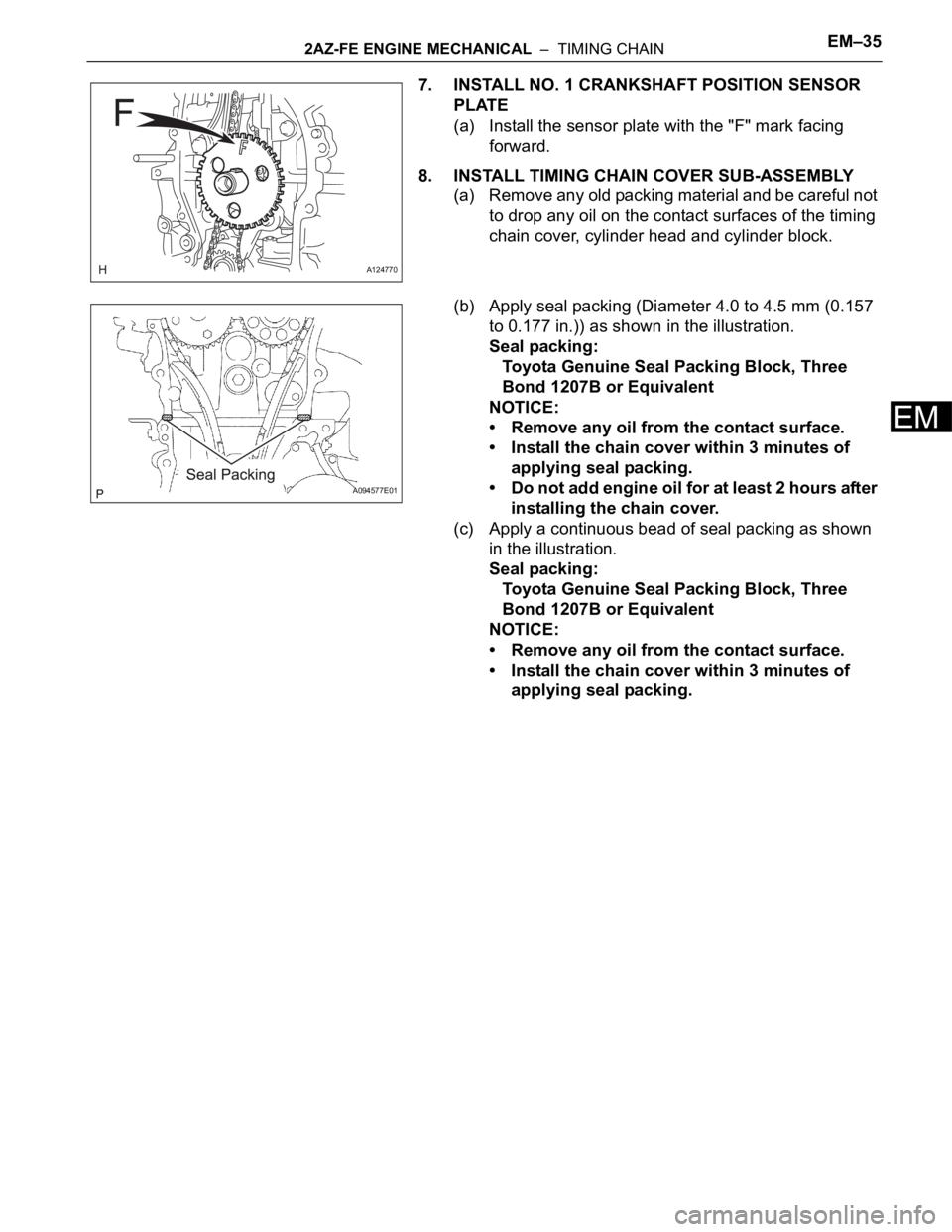
7. INSTALL NO. 1 CRANKSHAFT POSITION SENSOR
PLATE
(a) Install the sensor plate with the "F" mark facing
forward.
8. INSTALL TIMING CHAIN COVER SUB-ASSEMBLY
(a) Remove any old packing material and be careful not
to drop any oil on the contact surfaces of the timing
chain cover, cylinder head and cylinder block.
(b) Apply seal packing (Diameter 4.0 to 4.5 mm (0.157
to 0.177 in.)) as shown in the illustration.
Seal packing:
Toyota Genuine Seal Packing Block, Three
Bond 1207B or Equivalent
NOTICE:
• Remove any oil from the contact surface.
• Install the chain cover within 3 minutes of
applying seal packing.
• Do not add engine oil for at least 2 hours after
installing the chain cover.
(c) Apply a continuous bead of seal packing as shown
in the illustration.
Seal packing:
Toyota Genuine Seal Packing Block, Three
Bond 1207B or Equivalent
NOTICE:
• Remove any oil from the contact surface.
• Install the chain cover within 3 minutes of
applying seal packing.
A124770
A094577E01
Page 597 of 2000

EM–402AZ-FE ENGINE MECHANICAL – TIMING CHAIN
EM
(d) Uniformly tighten the 12 bolts and 2 nuts in the
sequence shown in the illustration.
Torque: 9.0 N*m (92 kgf*cm, 80 in.*lbf)
(e) Place a transmission jack underneath the engine,
then put a wooden block on the jack.
(f) Remove the chain block and sling device.
(g) Remove the No. 1 and No. 2 engine hangers.
14. INSTALL CRANKSHAFT POSITION SENSOR (See
page ES-402)
15. INSTALL CYLINDER HEAD COVER SUB-ASSEMBLY
(a) Remove any old packing material from the contact
surface.
(b) Apply seal packing to the 2 locations shown in the
illustration.
Seal packing:
Toyota Genuine Seal Packing Block, Three
Bond 1207B or Equivalent
NOTICE:
• Remove any oil from the contact surface.
• Install the oil pan within 3 minutes of applying
seal packing.
• Do not add engine oil for at least 2 hours after
installing the oil pan.
(c) Install the cylinder head cover with the 8 bolts and 2
nuts.
Torque: 11 N*m (112 kgf*cm, 8 ft.*lbf) for bolt A
14 N*m (143 kgf*cm, 10 ft.*lbf) for bolt B
11 N*m (112 kgf*cm, 8 ft.*lbf) for nut
A114333E01
A061184E04
A094205E01
A094204E01
Page 603 of 2000
2AZ-FE ENGINE MECHANICAL – CYLINDER HEADEM–59
EM
23. DISCONNECT ENGINE WIRE
(a) Disconnect the radio setting condenser connector.
(b) Disconnect the engine oil pressure switch
connector.
(c) Disconnect the engine coolant temperature sensor
connector.
(d) Disconnect the camshaft position sensor connector.
(e) Remove the bolt and ground cable.
24. REMOVE FRONT SUSPENSION MEMBER
REINFORCEMENT RH (See page EM-6)
25. REMOVE FAN AND GENERATOR V BELT (See page
EM-6)
26. REMOVE GENERATOR ASSEMBLY (See page CH-9)
27. REMOVE ENGINE MOUNTING INSULATOR RH (See
page EM-22)
28. REMOVE IDLER PULLEY (See page EM-23)
29. REMOVE IGNITION COIL ASSEMBLY (See page IG-9)
30. REMOVE SPARK PLUG (See page EM-8)
31. REMOVE CYLINDER HEAD COVER SUB-ASSEMBLY
(See page EM-24)
32. REMOVE V-RIBBED BELT TENSIONER ASSEMBLY
(See page EM-26)
33. REMOVE CRANKSHAFT POSITION SENSOR (See
page ES-402)
34. REMOVE OIL PAN SUB-ASSEMBLY (See page EM-
24)
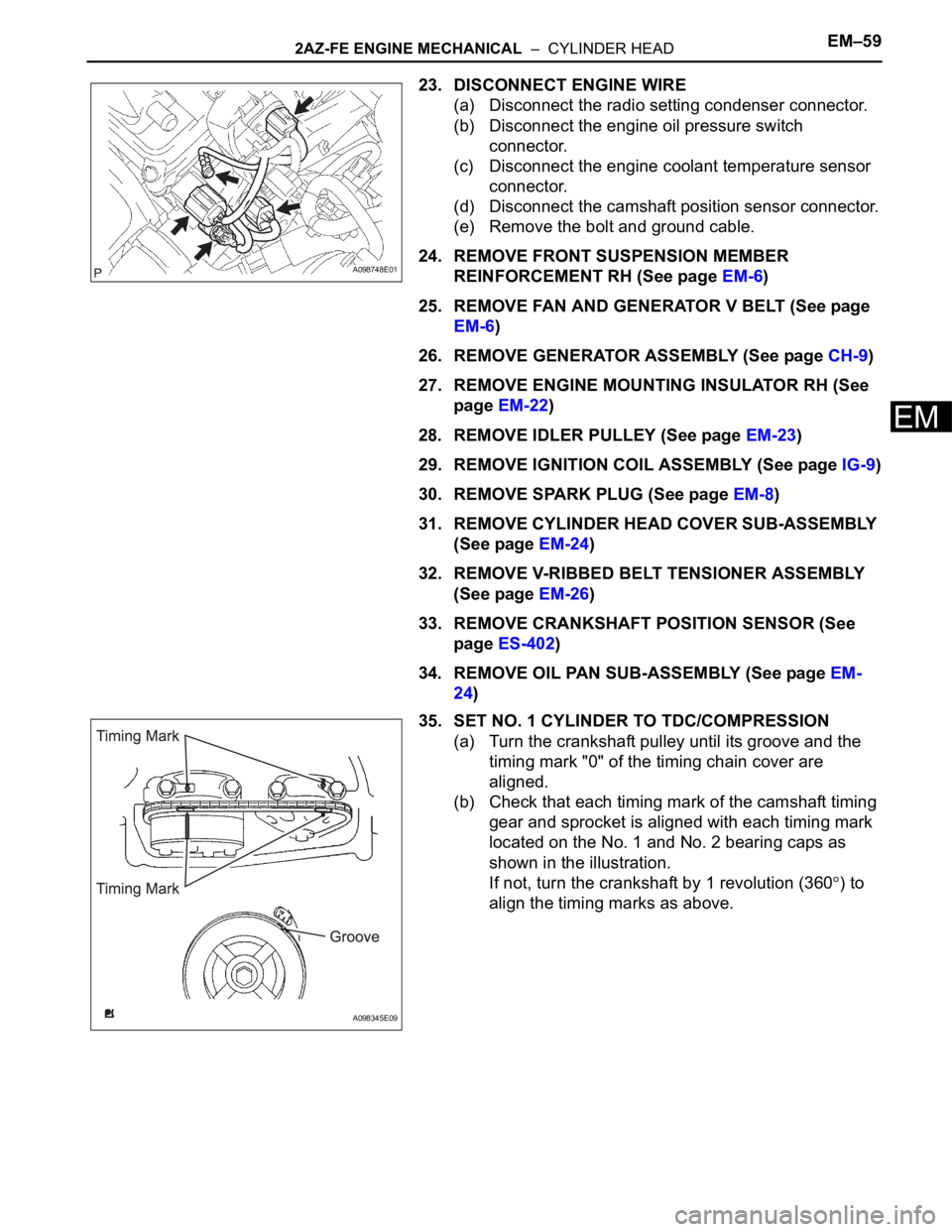
35. SET NO. 1 CYLINDER TO TDC/COMPRESSION
(a) Turn the crankshaft pulley until its groove and the
timing mark "0" of the timing chain cover are
aligned.
(b) Check that each timing mark of the camshaft timing
gear and sprocket is aligned with each timing mark
located on the No. 1 and No. 2 bearing caps as
shown in the illustration.
If not, turn the crankshaft by 1 revolution (360
) to
align the timing marks as above.
A098748E01
A098345E09
Page 605 of 2000
2AZ-FE ENGINE MECHANICAL – CYLINDER HEADEM–61
EM
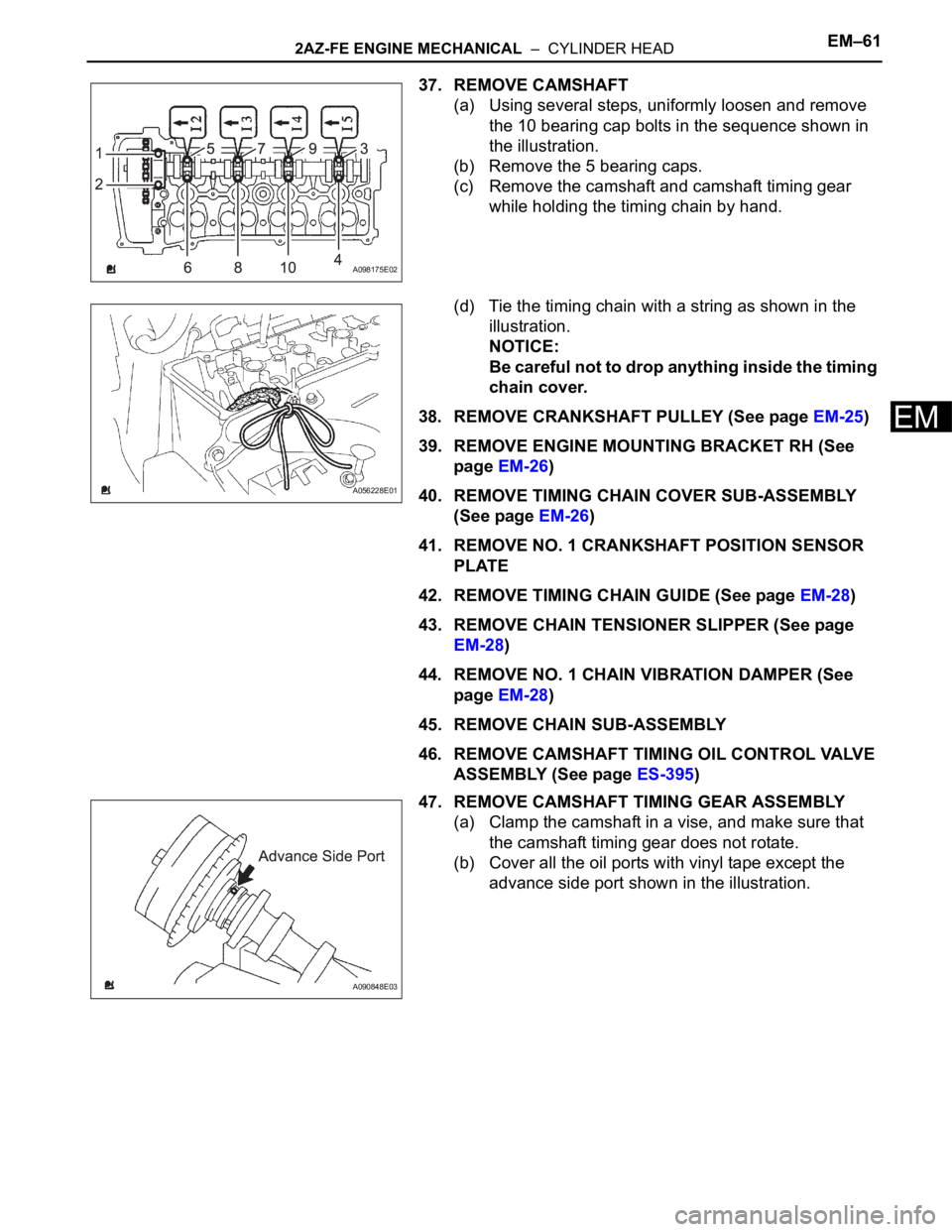
37. REMOVE CAMSHAFT
(a) Using several steps, uniformly loosen and remove
the 10 bearing cap bolts in the sequence shown in
the illustration.
(b) Remove the 5 bearing caps.
(c) Remove the camshaft and camshaft timing gear
while holding the timing chain by hand.
(d) Tie the timing chain with a string as shown in the
illustration.
NOTICE:
Be careful not to drop anything inside the timing
chain cover.
38. REMOVE CRANKSHAFT PULLEY (See page EM-25)
39. REMOVE ENGINE MOUNTING BRACKET RH (See
page EM-26)
40. REMOVE TIMING CHAIN COVER SUB-ASSEMBLY
(See page EM-26)
41. REMOVE NO. 1 CRANKSHAFT POSITION SENSOR
PLATE
42. REMOVE TIMING CHAIN GUIDE (See page EM-28)
43. REMOVE CHAIN TENSIONER SLIPPER (See page
EM-28)
44. REMOVE NO. 1 CHAIN VIBRATION DAMPER (See
page EM-28)
45. REMOVE CHAIN SUB-ASSEMBLY
46. REMOVE CAMSHAFT TIMING OIL CONTROL VALVE
ASSEMBLY (See page ES-395)
47. REMOVE CAMSHAFT TIMING GEAR ASSEMBLY
(a) Clamp the camshaft in a vise, and make sure that
the camshaft timing gear does not rotate.
(b) Cover all the oil ports with vinyl tape except the
advance side port shown in the illustration.
A098175E02
A056228E01
A090848E03