differential TOYOTA RAV4 2006 Service Manual Online
[x] Cancel search | Manufacturer: TOYOTA, Model Year: 2006, Model line: RAV4, Model: TOYOTA RAV4 2006Pages: 2000, PDF Size: 45.84 MB
Page 1437 of 2000
DIFFERENTIAL – REAR DIFFERENTIAL CARRIER ASSEMBLYDF–33
DF
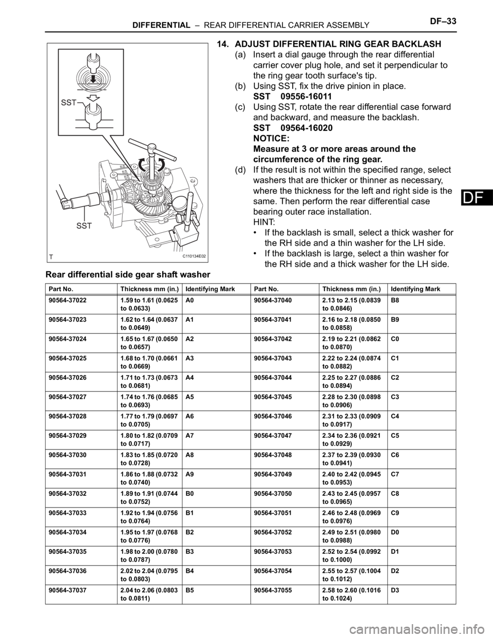
14. ADJUST DIFFERENTIAL RING GEAR BACKLASH
(a) Insert a dial gauge through the rear differential
carrier cover plug hole, and set it perpendicular to
the ring gear tooth surface's tip.
(b) Using SST, fix the drive pinion in place.
SST 09556-16011
(c) Using SST, rotate the rear differential case forward
and backward, and measure the backlash.
SST 09564-16020
NOTICE:
Measure at 3 or more areas around the
circumference of the ring gear.
(d) If the result is not within the specified range, select
washers that are thicker or thinner as necessary,
where the thickness for the left and right side is the
same. Then perform the rear differential case
bearing outer race installation.
HINT:
• If the backlash is small, select a thick washer for
the RH side and a thin washer for the LH side.
• If the backlash is large, select a thin washer for
the RH side and a thick washer for the LH side.
Rear differential side gear shaft washer
C110134E02
Part No. Thickness mm (in.) Identifying Mark Part No. Thickness mm (in.) Identifying Mark
90564-37022 1.59 to 1.61 (0.0625
to 0.0633)A0 90564-37040 2.13 to 2.15 (0.0839
to 0.0846)B8
90564-37023 1.62 to 1.64 (0.0637
to 0.0649)A1 90564-37041 2.16 to 2.18 (0.0850
to 0.0858)B9
90564-37024 1.65 to 1.67 (0.0650
to 0.0657)A2 90564-37042 2.19 to 2.21 (0.0862
to 0.0870)C0
90564-37025 1.68 to 1.70 (0.0661
to 0.0669)A3 90564-37043 2.22 to 2.24 (0.0874
to 0.0882)C1
90564-37026 1.71 to 1.73 (0.0673
to 0.0681)A4 90564-37044 2.25 to 2.27 (0.0886
to 0.0894)C2
90564-37027 1.74 to 1.76 (0.0685
to 0.0693)A5 90564-37045 2.28 to 2.30 (0.0898
to 0.0906)C3
90564-37028 1.77 to 1.79 (0.0697
to 0.0705)A6 90564-37046 2.31 to 2.33 (0.0909
to 0.0917)C4
90564-37029 1.80 to 1.82 (0.0709
to 0.0717)A7 90564-37047 2.34 to 2.36 (0.0921
to 0.0929)C5
90564-37030 1.83 to 1.85 (0.0720
to 0.0728)A8 90564-37048 2.37 to 2.39 (0.0930
to 0.0941)C6
90564-37031 1.86 to 1.88 (0.0732
to 0.0740)A9 90564-37049 2.40 to 2.42 (0.0945
to 0.0953)C7
90564-37032 1.89 to 1.91 (0.0744
to 0.0752)B0 90564-37050 2.43 to 2.45 (0.0957
to 0.0965)C8
90564-37033 1.92 to 1.94 (0.0756
to 0.0764)B1 90564-37051 2.46 to 2.48 (0.0969
to 0.0976)C9
90564-37034 1.95 to 1.97 (0.0768
to 0.0776)B2 90564-37052 2.49 to 2.51 (0.0980
to 0.0988)D0
90564-37035 1.98 to 2.00 (0.0780
to 0.0787)B3 90564-37053 2.52 to 2.54 (0.0992
to 0.1000)D1
90564-37036 2.02 to 2.04 (0.0795
to 0.0803)B4 90564-37054 2.55 to 2.57 (0.1004
to 0.1012)D2
90564-37037 2.04 to 2.06 (0.0803
to 0.0811)B5 90564-37055 2.58 to 2.60 (0.1016
to 0.1024)D3
Page 1438 of 2000
DF–34DIFFERENTIAL – REAR DIFFERENTIAL CARRIER ASSEMBLY
DF
15. INSPECT TOOTH CONTACT BETWEEN RING GEAR
AND DRIVE PINION
(a) Remove the 8 bolts and differential side bearing
retainer from the rear differential carrier.
(b) Remove the rear differential carrier case.
(c) Uniformly apply a light coat of prussian blue on both
sides of the differential ring gear teeth.
(d) Install the rear differential case.
(e) Temporarily install the differential side bearing
retainer to the differential carrier with the 8 bolts.
(f) Rotate the differential side pinion several times.
(g) Remove the 8 bolts and rear differential side
bearing retainer from the differential carrier.
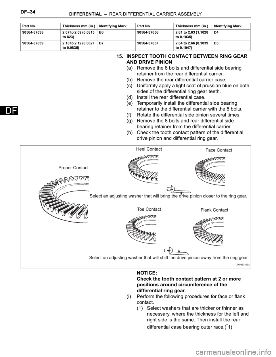
(h) Check the tooth contact pattern of the differential
drive pinion and differential ring gear.
NOTICE:
Check the tooth contact pattern at 2 or more
positions around circumference of the
differential ring gear.
(i) Perform the following procedures for face or flank
contact.
(1) Select washers that are thicker or thinner as
necessary, where the thickness for the left and
right side is the same. Then install the rear
differential case bearing outer race.(
*1)
90564-37038 2.07 to 2.09 (0.0815
to 823)B6 90564-37056 2.61 to 2.63 (1.1028
to 0.1035)D4
90564-37039 2.10 to 2.12 (0.0827
to 0.0835)B7 90564-37057 2.64 to 2.66 (0.1039
to 0.1047)D5 Part No. Thickness mm (in.) Identifying Mark Part No. Thickness mm (in.) Identifying Mark
ZK03673E02
Page 1439 of 2000
DIFFERENTIAL – REAR DIFFERENTIAL CARRIER ASSEMBLYDF–35
DF
(2) Repeat the differential ring gear and differential
drive pinion tooth contact pattern inspection.
HINT:
If the tooth contact pattern is not correct,
repeat*1.
(3) Repeat the differential ring gear and differential
drive pinion backlash inspection.
HINT:
If the differential ring gear and differential drive
pinion backlash is not as specified, replace the
differential ring gear and differential drive pinion
with new ones.
(j) Perform the following procedures for heel or toe
contact.
(1) Select a drive pinion washer again and perform
the rear drive pinion tapered roller bearing rear
installation.
Rear differential drive pinion washer
Part No. Thickness (mm) Identifying Mark Part No. Thickness (mm) Identifying Mark
90564-35041 1.695 to 1.705
(0.0667 to 0.0671)41 90564-35071 1.955 to 1.965
(0.0770 to 0.0774)71
90564-35042 1.705 to 1.715
(0.0671 to 0.0675)42 90564-35072 1.965 to 1.975
(0.0774 to 0.0778)72
90564-35043 1.715 to 1.725
(0.0675 to 0.0679)43 90564-35073 1.975 to 1.985
(0.0778 to 0.0781)73
90564-35044 1.725 to 1.735
(0.0679 to 0.0683)44 90564-35074 1.985 to 1.995
(0.0781 to 0.0785)74
90564-35045 1.735 to 1.745
(0.0683 to 0.0687)45 90564-35075 1.995 to 2.005
(0.0785 to 0.0789)75
90564-35046 1.745 to 1.755
(0.0687 to 0.0690)46 90564-35076 2.005 to 2.015
(0.0789 to 0.0793)76
90564-35047 1.755 to 1.765
(0.0690 to 0.0695)47 90564-35077 2.015 to 2.025
(0.0793 to 0.0797)77
90564-35048 1.765 to 1.775
(0.0695 to 0.0699)48 90564-35078 2.025 to 2.035
(0.0797 to 0.0801)78
90564-35049 1.775 to 1.785
(0.0699 to 0.0703)49 90564-35079 2.035 to 2.045
(0.0801 to 0.0805)79
90564-35050 1.785 to 1.795
(0.0703 to 0.0707)50 90564-35080 2.045 to 2.055
(0.0805 to 0.0809)80
90564-35051 1.795 to 1.805
(0.0707 to 0.0711)51 90564-35081 2.055 to 2.065
(0.0809 to 0.0813)81
90564-35052 1.805 to 1.815
(0.0707 to 0.0715)52 90564-35082 2.065 to 2.075
(0.0813 to 0.0817)82
90564-35053 1.815 to 1.825
(0.0715 to 0.0719)53 90564-35083 2.075 to 2.085
(0.0817 to 0.0821)83
90564-35054 1.825 to 1.835
(0.0719 to 0.0720)54 90564-35084 2.085 to 2.095
(0.0821 to 0.0825)84
90564-35055 1.835 to 1.845
(0.0719 to 0.0726)55 90564-35085 2.095 to 2.105
(0.0825 to 0.0829)85
90564-35056 1.845 to 1.855
(0.0726 to 0.0730)56 90564-35086 2.105 to 2.115
(0.0829 to 0.0833)86
90564-35057 1.855 to 1.865
(0.0730 to 0.0734)57 90564-35087 2.115 to 2.125
(0.0833 to 0.0837)87
90564-35058 1.865 to 1.875
(0.0734 to 0.0738)58 90564-35088 2.125 to 2.135
(0.0837 to 0.0841)88
90564-35059 1.875 to 1.885
(0.0734 to 0.0742)59 90564-35089 2.135 to 2.145
(0.0841 to 0.0844)89
Page 1440 of 2000
DF–36DIFFERENTIAL – REAR DIFFERENTIAL CARRIER ASSEMBLY
DF16. INSPECT TOTAL PRELOAD
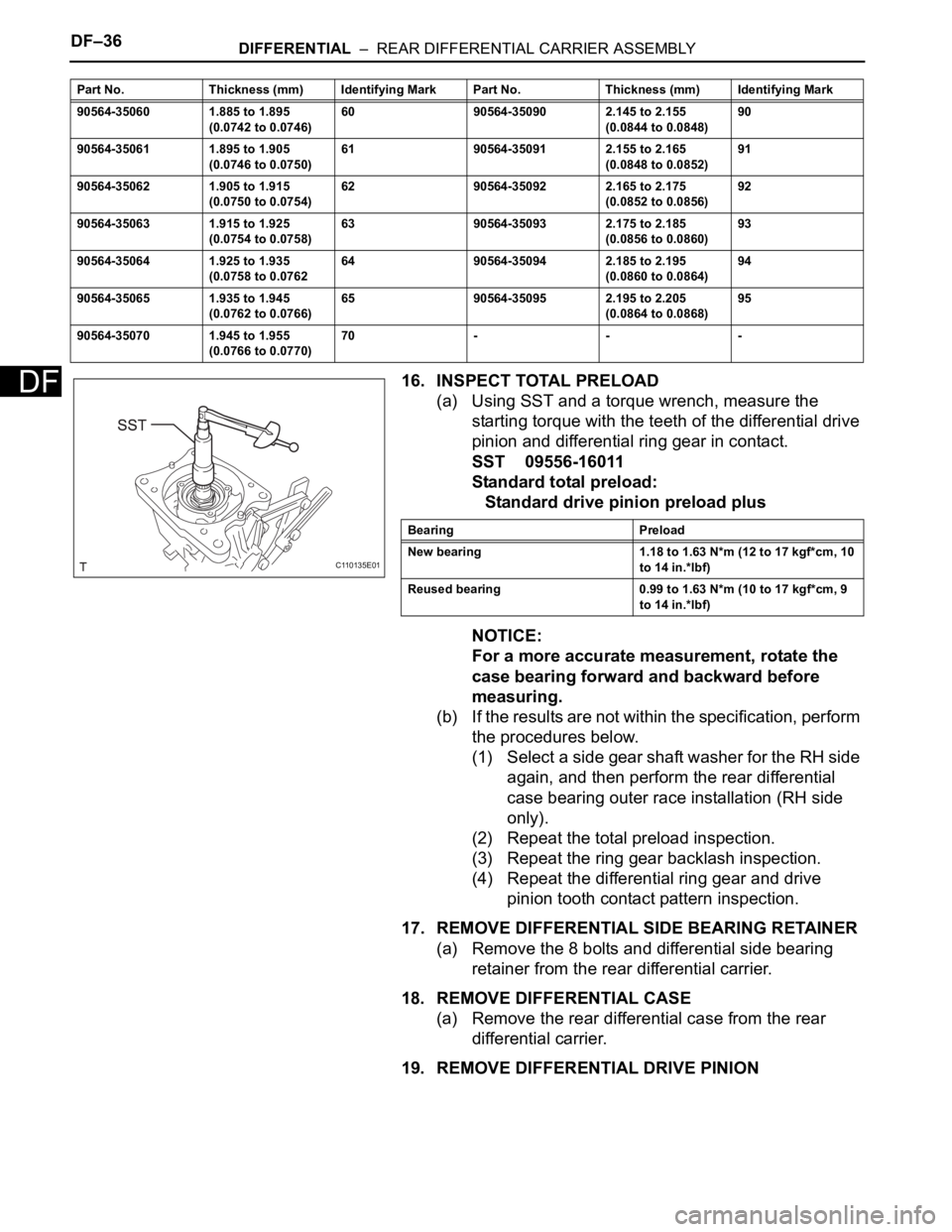
(a) Using SST and a torque wrench, measure the
starting torque with the teeth of the differential drive
pinion and differential ring gear in contact.
SST 09556-16011
Standard total preload:
Standard drive pinion preload plus
NOTICE:
For a more accurate measurement, rotate the
case bearing forward and backward before
measuring.
(b) If the results are not within the specification, perform
the procedures below.
(1) Select a side gear shaft washer for the RH side
again, and then perform the rear differential
case bearing outer race installation (RH side
only).
(2) Repeat the total preload inspection.
(3) Repeat the ring gear backlash inspection.
(4) Repeat the differential ring gear and drive
pinion tooth contact pattern inspection.
17. REMOVE DIFFERENTIAL SIDE BEARING RETAINER
(a) Remove the 8 bolts and differential side bearing
retainer from the rear differential carrier.
18. REMOVE DIFFERENTIAL CASE
(a) Remove the rear differential case from the rear
differential carrier.
19. REMOVE DIFFERENTIAL DRIVE PINION
90564-35060 1.885 to 1.895
(0.0742 to 0.0746)60 90564-35090 2.145 to 2.155
(0.0844 to 0.0848)90
90564-35061 1.895 to 1.905
(0.0746 to 0.0750)61 90564-35091 2.155 to 2.165
(0.0848 to 0.0852)91
90564-35062 1.905 to 1.915
(0.0750 to 0.0754)62 90564-35092 2.165 to 2.175
(0.0852 to 0.0856)92
90564-35063 1.915 to 1.925
(0.0754 to 0.0758)63 90564-35093 2.175 to 2.185
(0.0856 to 0.0860)93
90564-35064 1.925 to 1.935
(0.0758 to 0.076264 90564-35094 2.185 to 2.195
(0.0860 to 0.0864)94
90564-35065 1.935 to 1.945
(0.0762 to 0.0766)65 90564-35095 2.195 to 2.205
(0.0864 to 0.0868)95
90564-35070 1.945 to 1.955
(0.0766 to 0.0770)70--- Part No. Thickness (mm) Identifying Mark Part No. Thickness (mm) Identifying Mark
C110135E01
Bearing Preload
New bearing 1.18 to 1.63 N*m (12 to 17 kgf*cm, 10
to 14 in.*lbf)
Reused bearing 0.99 to 1.63 N*m (10 to 17 kgf*cm, 9
to 14 in.*lbf)
Page 1441 of 2000
DIFFERENTIAL – REAR DIFFERENTIAL CARRIER ASSEMBLYDF–37
DF
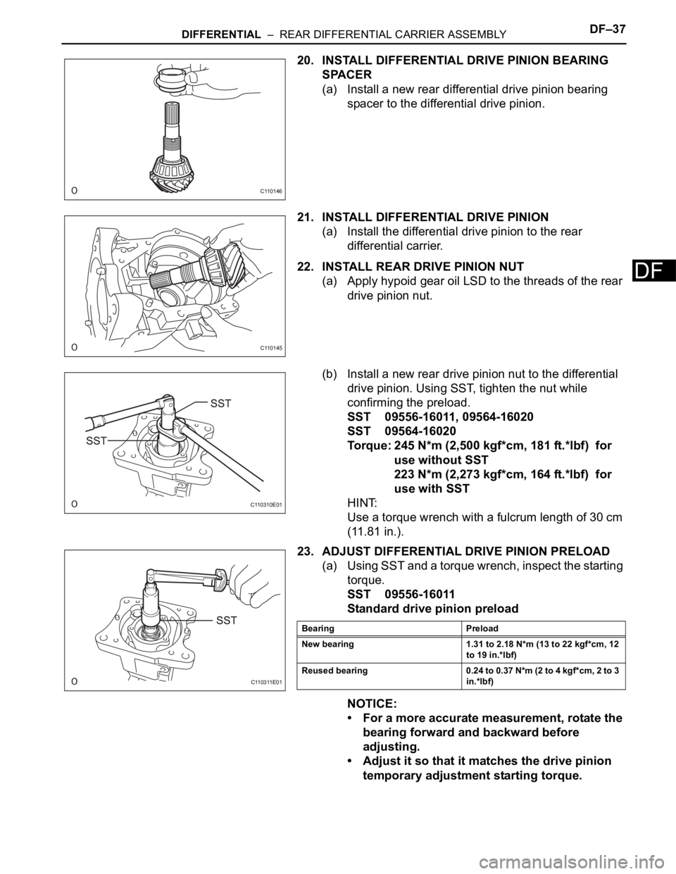
20. INSTALL DIFFERENTIAL DRIVE PINION BEARING
SPACER
(a) Install a new rear differential drive pinion bearing
spacer to the differential drive pinion.
21. INSTALL DIFFERENTIAL DRIVE PINION
(a) Install the differential drive pinion to the rear
differential carrier.
22. INSTALL REAR DRIVE PINION NUT
(a) Apply hypoid gear oil LSD to the threads of the rear
drive pinion nut.
(b) Install a new rear drive pinion nut to the differential
drive pinion. Using SST, tighten the nut while
confirming the preload.
SST 09556-16011, 09564-16020
SST 09564-16020
Torque: 245 N*m (2,500 kgf*cm, 181 ft.*lbf) for
use without SST
223 N*m (2,273 kgf*cm, 164 ft.*lbf) for
use with SST
HINT:
Use a torque wrench with a fulcrum length of 30 cm
(11.81 in.).
23. ADJUST DIFFERENTIAL DRIVE PINION PRELOAD
(a) Using SST and a torque wrench, inspect the starting
torque.
SST 09556-16011
Standard drive pinion preload
NOTICE:
• For a more accurate measurement, rotate the
bearing forward and backward before
adjusting.
• Adjust it so that it matches the drive pinion
temporary adjustment starting torque.
C110146
C110145
C110310E01
C110311E01
Bearing Preload
New bearing 1.31 to 2.18 N*m (13 to 22 kgf*cm, 12
to 19 in.*lbf)
Reused bearing 0.24 to 0.37 N*m (2 to 4 kgf*cm, 2 to 3
in.*lbf)
Page 1442 of 2000

DF–38DIFFERENTIAL – REAR DIFFERENTIAL CARRIER ASSEMBLY
DF
(b) If the preload is insufficient, use SST to tighten the
drive pinion nut 5 to 10
at a time. Measure the
starting torque and repeat the adjustment as
necessary until the preload matches the specified
torque.
SST 09564-16020
(c) If the tightening torque of the rear drive pinion nut
exceeds 245 N*m { 2500 kgf*cm } but the preload is
still insufficient, loosen the rear drive pinion nut.
Then check if the rear drive pinion nut and
differential drive pinion screw threads are damaged.
(d) If there is no defect, replace the rear drive
differential drive pinion bearing spacer, apply hypoid
gear oil LSD to its threads and repeat the procedure
above.
24. INSTALL DIFFERENTIAL CASE
25. INSTALL DIFFERENTIAL SIDE BEARING RETAINER
(a) Install the differential side bearing retainer to the
rear differential carrier with the 8 bolts.
Torque: 34 N*m (350 kgf*cm, 25 ft.*lbf)
26. INSPECT DIFFERENTIAL RING GEAR BACKLASH
27. INSPECT TOTAL PRELOAD
(a) Using SST and a torque wrench, measure the
starting torque with the teeth of the differential drive
pinion and differential ring gear in contact.
SST 09556-16011
Standard total preload:
Standard drive pinion preload plus
NOTICE:
For a more accurate measurement, rotate the
case bearing forward and backward before
measuring.
(b) If the results are not within the specified range,
select a rear differential side gear shaft washer for
the RH side again, and then perform the rear
differential case bearing outer race installation (RH
side only).
NOTICE:
If using a different rear differential side gear
shaft washer, adjust the ring gear backlash.
Then adjust the total preload.
28. REMOVE DIFFERENTIAL SIDE BEARING RETAINER
(a) Remove the 8 bolts and side bearing retainer from
the rear differential carrier.
C110310E01
C110135E01
Bearing Preload
New bearing 1.18 to 1.90 N*m (12 to 19 kgf*cm, 10
to 17 in.*lbf)
Reused bearing 0.99 to 1.63 N*m (10 to 17 kgf*cm, 9
to 14 in.*lbf)
Page 1443 of 2000

DIFFERENTIAL – REAR DIFFERENTIAL CARRIER ASSEMBLYDF–39
DF
29. INSTALL DIFFERENTIAL SIDE BEARING RETAINER
(a) Using white gasoline, remove grease and oil from
the alignment surfaces of the rear differential carrier
and differential side bearing retainer.
(b) Apply seal packing to the areas indicated in the
illustration of the differential side bearing retainer.
Seal Packing:
Toyota Genuine Seal Packing 1281, Three
Bond 1281 or equivalent
NOTICE:
• Apply seal packing in a continuous line 2 to 3
mm (0.08 to 0.12 in.) in diameter.
• Perform the installation with 3 minutes of
applying seal packing.
(c) Install the differential side bearing retainer to the
rear differential carrier with the 8 bolts.
Torque: 34 N*m (350 kgf*cm, 25 ft.*lbf)
NOTICE:
After installing the cover, do not add oil or drive
the vehicle, and leave it alone for 1 hour or
more. Also, avoid sudden acceleration and
deceleration for 12 hours or more.
30. INSPECT TOTAL PRELOAD
(a) Using SST and a torque wrench, inspect the starting
torque with the teeth of the differential drive pinion
and differential ring gear in contact.
SST 09556-16011
Standard total preload:
Standard drive pinion preload plus
NOTICE:
For a more accurate measurement, rotate the
case bearing forward and backward before
inspecting.
C110312E01
C110142
C110135E01
Bearing Preload
New bearing 1.18 to 1.90 N*m (12 to 19 kgf*cm, 10
to 17 in.*lbf)
Reused bearing 0.99 to 1.63 N*m (10 to 17 kgf*cm, 9
to 14 in.*lbf)
Page 1444 of 2000
DF–40DIFFERENTIAL – REAR DIFFERENTIAL CARRIER ASSEMBLY
DF
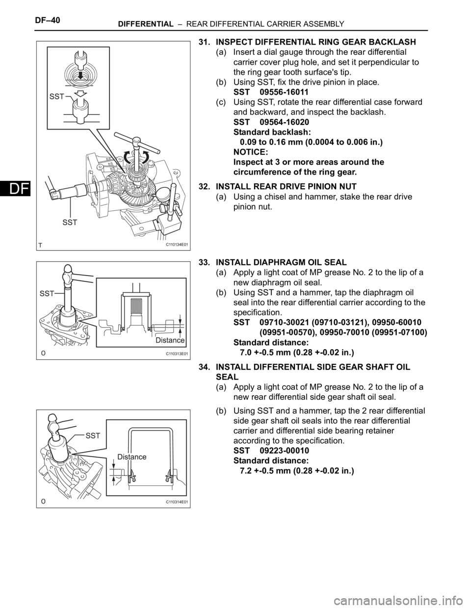
31. INSPECT DIFFERENTIAL RING GEAR BACKLASH
(a) Insert a dial gauge through the rear differential
carrier cover plug hole, and set it perpendicular to
the ring gear tooth surface's tip.
(b) Using SST, fix the drive pinion in place.
SST 09556-16011
(c) Using SST, rotate the rear differential case forward
and backward, and inspect the backlash.
SST 09564-16020
Standard backlash:
0.09 to 0.16 mm (0.0004 to 0.006 in.)
NOTICE:
Inspect at 3 or more areas around the
circumference of the ring gear.
32. INSTALL REAR DRIVE PINION NUT
(a) Using a chisel and hammer, stake the rear drive
pinion nut.
33. INSTALL DIAPHRAGM OIL SEAL
(a) Apply a light coat of MP grease No. 2 to the lip of a
new diaphragm oil seal.
(b) Using SST and a hammer, tap the diaphragm oil
seal into the rear differential carrier according to the
specification.
SST 09710-30021 (09710-03121), 09950-60010
(09951-00570), 09950-70010 (09951-07100)
Standard distance:
7.0 +-0.5 mm (0.28 +-0.02 in.)
34. INSTALL DIFFERENTIAL SIDE GEAR SHAFT OIL
SEAL
(a) Apply a light coat of MP grease No. 2 to the lip of a
new rear differential side gear shaft oil seal.
(b) Using SST and a hammer, tap the 2 rear differential
side gear shaft oil seals into the rear differential
carrier and differential side bearing retainer
according to the specification.
SST 09223-00010
Standard distance:
7.2 +-0.5 mm (0.28 +-0.02 in.)
C110134E01
C110313E01
C110314E01
Page 1445 of 2000
DIFFERENTIAL – REAR DIFFERENTIAL CARRIER ASSEMBLYDF–41
DF
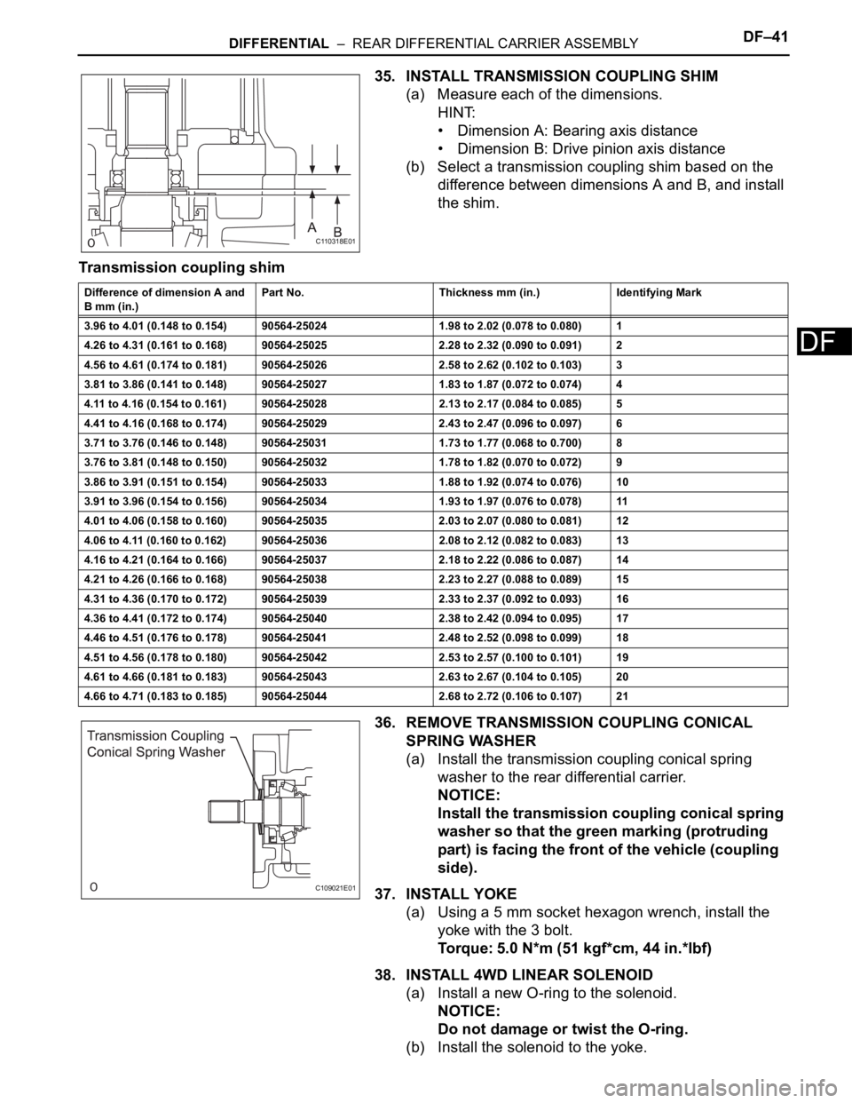
35. INSTALL TRANSMISSION COUPLING SHIM
(a) Measure each of the dimensions.
HINT:
• Dimension A: Bearing axis distance
• Dimension B: Drive pinion axis distance
(b) Select a transmission coupling shim based on the
difference between dimensions A and B, and install
the shim.
Transmission coupling shim
36. REMOVE TRANSMISSION COUPLING CONICAL
SPRING WASHER
(a) Install the transmission coupling conical spring
washer to the rear differential carrier.
NOTICE:
Install the transmission coupling conical spring
washer so that the green marking (protruding
part) is facing the front of the vehicle (coupling
side).
37. INSTALL YOKE
(a) Using a 5 mm socket hexagon wrench, install the
yoke with the 3 bolt.
Torque: 5.0 N*m (51 kgf*cm, 44 in.*lbf)
38. INSTALL 4WD LINEAR SOLENOID
(a) Install a new O-ring to the solenoid.
NOTICE:
Do not damage or twist the O-ring.
(b) Install the solenoid to the yoke.
C110318E01
Difference of dimension A and
B mm (in.)Part No. Thickness mm (in.) Identifying Mark
3.96 to 4.01 (0.148 to 0.154) 90564-25024 1.98 to 2.02 (0.078 to 0.080) 1
4.26 to 4.31 (0.161 to 0.168) 90564-25025 2.28 to 2.32 (0.090 to 0.091) 2
4.56 to 4.61 (0.174 to 0.181) 90564-25026 2.58 to 2.62 (0.102 to 0.103) 3
3.81 to 3.86 (0.141 to 0.148) 90564-25027 1.83 to 1.87 (0.072 to 0.074) 4
4.11 to 4.16 (0.154 to 0.161) 90564-25028 2.13 to 2.17 (0.084 to 0.085) 5
4.41 to 4.16 (0.168 to 0.174) 90564-25029 2.43 to 2.47 (0.096 to 0.097) 6
3.71 to 3.76 (0.146 to 0.148) 90564-25031 1.73 to 1.77 (0.068 to 0.700) 8
3.76 to 3.81 (0.148 to 0.150) 90564-25032 1.78 to 1.82 (0.070 to 0.072) 9
3.86 to 3.91 (0.151 to 0.154) 90564-25033 1.88 to 1.92 (0.074 to 0.076) 10
3.91 to 3.96 (0.154 to 0.156) 90564-25034 1.93 to 1.97 (0.076 to 0.078) 11
4.01 to 4.06 (0.158 to 0.160) 90564-25035 2.03 to 2.07 (0.080 to 0.081) 12
4.06 to 4.11 (0.160 to 0.162) 90564-25036 2.08 to 2.12 (0.082 to 0.083) 13
4.16 to 4.21 (0.164 to 0.166) 90564-25037 2.18 to 2.22 (0.086 to 0.087) 14
4.21 to 4.26 (0.166 to 0.168) 90564-25038 2.23 to 2.27 (0.088 to 0.089) 15
4.31 to 4.36 (0.170 to 0.172) 90564-25039 2.33 to 2.37 (0.092 to 0.093) 16
4.36 to 4.41 (0.172 to 0.174) 90564-25040 2.38 to 2.42 (0.094 to 0.095) 17
4.46 to 4.51 (0.176 to 0.178) 90564-25041 2.48 to 2.52 (0.098 to 0.099) 18
4.51 to 4.56 (0.178 to 0.180) 90564-25042 2.53 to 2.57 (0.100 to 0.101) 19
4.61 to 4.66 (0.181 to 0.183) 90564-25043 2.63 to 2.67 (0.104 to 0.105) 20
4.66 to 4.71 (0.183 to 0.185) 90564-25044 2.68 to 2.72 (0.106 to 0.107) 21
C109021E01
Page 1446 of 2000
DF–42DIFFERENTIAL – REAR DIFFERENTIAL CARRIER ASSEMBLY
DF
(c) Install the snap ring.
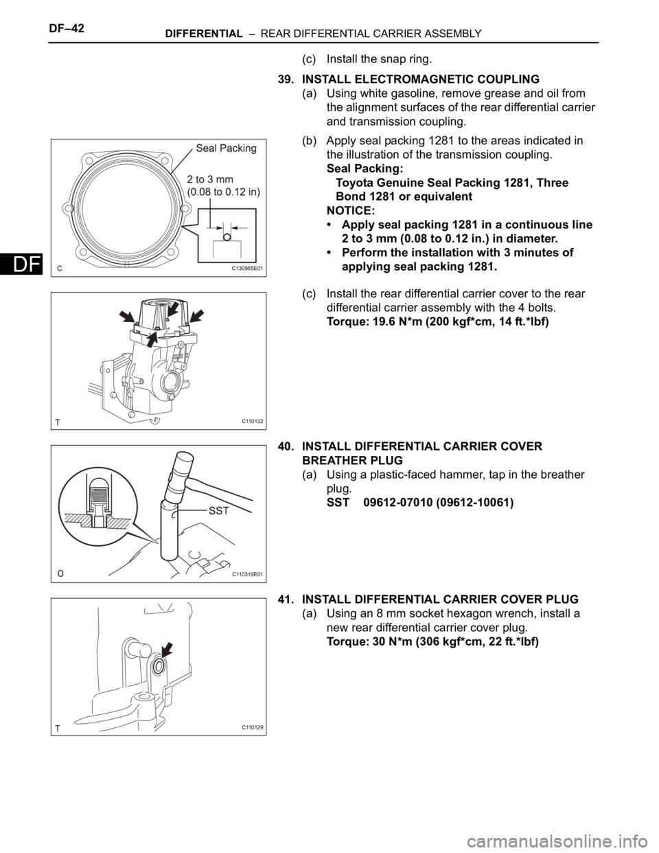
39. INSTALL ELECTROMAGNETIC COUPLING
(a) Using white gasoline, remove grease and oil from
the alignment surfaces of the rear differential carrier
and transmission coupling.
(b) Apply seal packing 1281 to the areas indicated in
the illustration of the transmission coupling.
Seal Packing:
Toyota Genuine Seal Packing 1281, Three
Bond 1281 or equivalent
NOTICE:
• Apply seal packing 1281 in a continuous line
2 to 3 mm (0.08 to 0.12 in.) in diameter.
• Perform the installation with 3 minutes of
applying seal packing 1281.
(c) Install the rear differential carrier cover to the rear
differential carrier assembly with the 4 bolts.
Torque: 19.6 N*m (200 kgf*cm, 14 ft.*lbf)
40. INSTALL DIFFERENTIAL CARRIER COVER
BREATHER PLUG
(a) Using a plastic-faced hammer, tap in the breather
plug.
SST 09612-07010 (09612-10061)
41. INSTALL DIFFERENTIAL CARRIER COVER PLUG
(a) Using an 8 mm socket hexagon wrench, install a
new rear differential carrier cover plug.
Torque: 30 N*m (306 kgf*cm, 22 ft.*lbf)
C130565E01
C110132
C110319E01
C110129