height TOYOTA RAV4 2019 Owners Manual (in English)
[x] Cancel search | Manufacturer: TOYOTA, Model Year: 2019, Model line: RAV4, Model: TOYOTA RAV4 2019Pages: 728, PDF Size: 21.09 MB
Page 31 of 728
311-1. For safe use
1
For safety and security
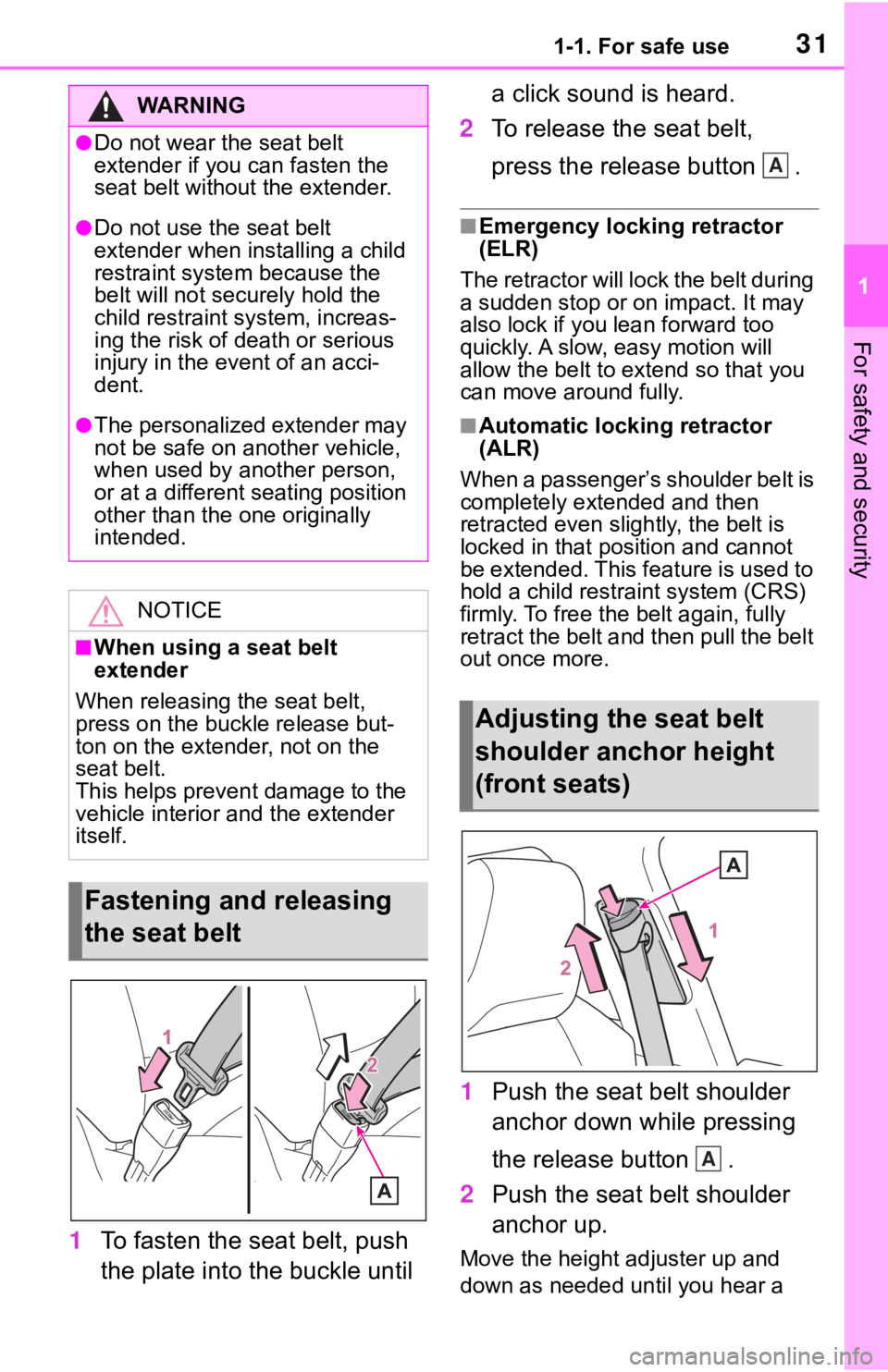
1To fasten the seat belt, push
the plate into the buckle until a click sound is heard.
2 To release the seat belt,
press the release button .
■Emergency locking retractor
(ELR)
The retractor will lock the belt during
a sudden stop or on impact. It may
also lock if you lean forward too
quickly. A slow, easy motion will
allow the belt to extend so that you
can move around fully.
■Automatic locking retractor
(ALR)
When a passenger’s shoulder belt is
completely extended and then
retracted even slightly, the belt is
locked in that position and cannot
be extended. This feature is used to
hold a child restraint system (CRS)
firmly. To free the belt again, fully
retract the belt and then pull the belt
out once more.
1 Push the seat belt shoulder
anchor down while pressing
the release button .
2 Push the seat belt shoulder
anchor up.
Move the height adjuster up and
down as needed until you hear a
WA R N I N G
●Do not wear the seat belt
extender if you can fasten the
seat belt without the extender.
●Do not use the seat belt
extender when installing a child
restraint system because the
belt will not securely hold the
child restraint system, increas-
ing the risk of death or serious
injury in the event of an acci-
dent.
●The personalized extender may
not be safe on another vehicle,
when used by another person,
or at a different seating position
other than the one originally
intended.
NOTICE
■When using a seat belt
extender
When releasing the seat belt,
press on the buckle release but-
ton on the extender, not on the
seat belt.
This helps prevent damage to the
vehicle interior and the extender
itself.
Fastening and releasing
the seat belt
Adjusting the seat belt
shoulder anchor height
(front seats)
A
A
Page 135 of 728
1353-3. Adjusting the seats
3
Before driving
3-3.Adjusting the seats
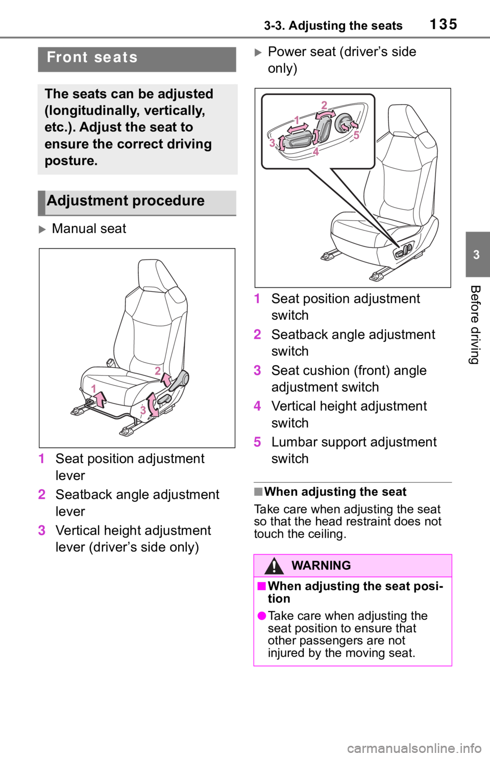
Manual seat
1 Seat position adjustment
lever
2 Seatback angle adjustment
lever
3 Vertical height adjustment
lever (driver’s side only)
Power seat (driver’s side
only)
1 Seat position adjustment
switch
2 Seatback angle adjustment
switch
3 Seat cushion (front) angle
adjustment switch
4 Vertical height adjustment
switch
5 Lumbar support adjustment
switch
■When adjusting the seat
Take care when adjusting the seat
so that the head restraint does not
touch the ceiling.
Front seats
The seats can be adjusted
(longitudinally, vertically,
etc.). Adjust the seat to
ensure the correct driving
posture.
Adjustment procedure
WA R N I N G
■When adjusting the seat posi-
tion
●Take care when adjusting the
seat position to ensure that
other passengers are not
injured by the moving seat.
Page 142 of 728
1423-3. Adjusting the seats
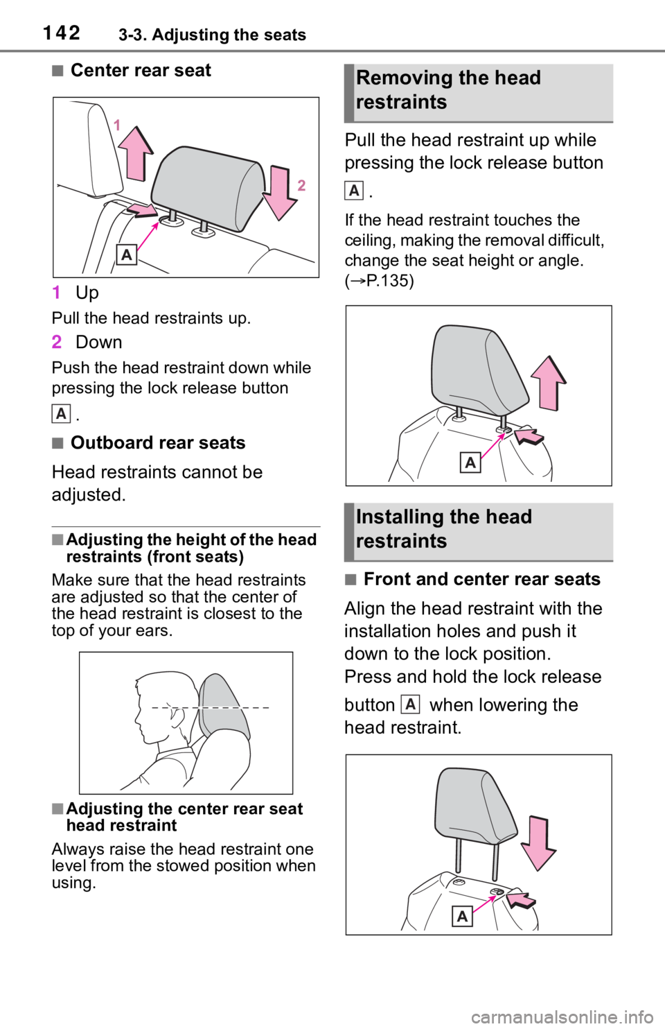
■Center rear seat
1 Up
Pull the head restraints up.
2Down
Push the head restraint down while
pressing the lock release button
.
■Outboard rear seats
Head restraints cannot be
adjusted.
■Adjusting the height of the head
restraints (front seats)
Make sure that the head restraints
are adjusted so that the center of
the head restraint is closest to the
top of your ears.
■Adjusting the center rear seat
head restraint
Always raise the head restraint one
level from the stowed position when
using.
Pull the head restraint up while
pressing the lock release button
.
If the head restrai nt touches the
ceiling, making the removal difficult,
change the seat height or angle.
( P.135)
■Front and center rear seats
Align the head restraint with the
installation holes and push it
down to the lock position.
Press and hold the lock release
button when lowering the
head restraint.
A
Removing the head
restraints
Installing the head
restraints
A
A
Page 145 of 728
1453-4. Adjusting the steering wheel and mirrors
3
Before driving
*: If equipped
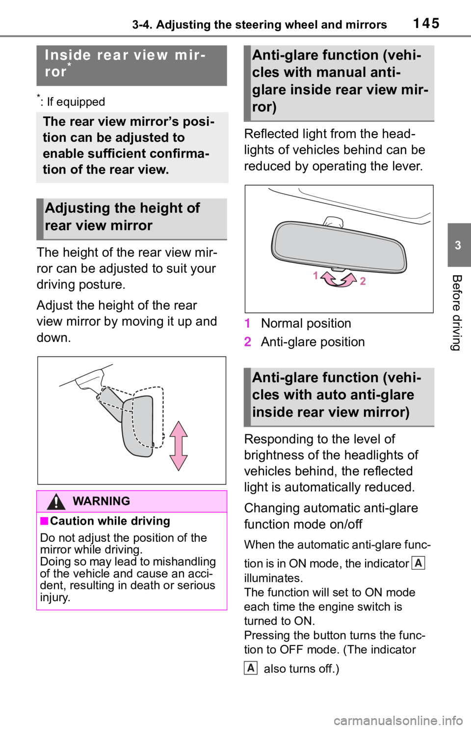
The height of the rear view mir-
ror can be adjusted to suit your
driving posture.
Adjust the height of the rear
view mirror by moving it up and
down.Reflected light from the head-
lights of vehicles behind can be
reduced by operating the lever.
1
Normal position
2 Anti-glare position
Responding to the level of
brightness of the headlights of
vehicles behind, the reflected
light is automatically reduced.
Changing automatic anti-glare
function mode on/off
When the automatic anti-glare func-
tion is in ON mode, the indicator
illuminates.
The function will set to ON mode
each time the engine switch is
turned to ON.
Pressing the button turns the func-
tion to OFF mode. (The indicator also turns off.)
Inside rear view mir-
ror*
The rear view mirror’s posi-
tion can be adjusted to
enable sufficient confirma-
tion of the rear view.
Adjusting the height of
rear view mirror
WA R N I N G
■Caution while driving
Do not adjust the position of the
mirror while driving.
Doing so may lead to mishandling
of the vehicle and cause an acci-
dent, resulting in death or serious
injury.
Anti-glare function (vehi-
cles with manual anti-
glare inside rear view mir-
ror)
Anti-glare function (vehi-
cles with auto anti-glare
inside rear view mirror)
A
A
Page 148 of 728
1483-4. Adjusting the steering wheel and mirrors
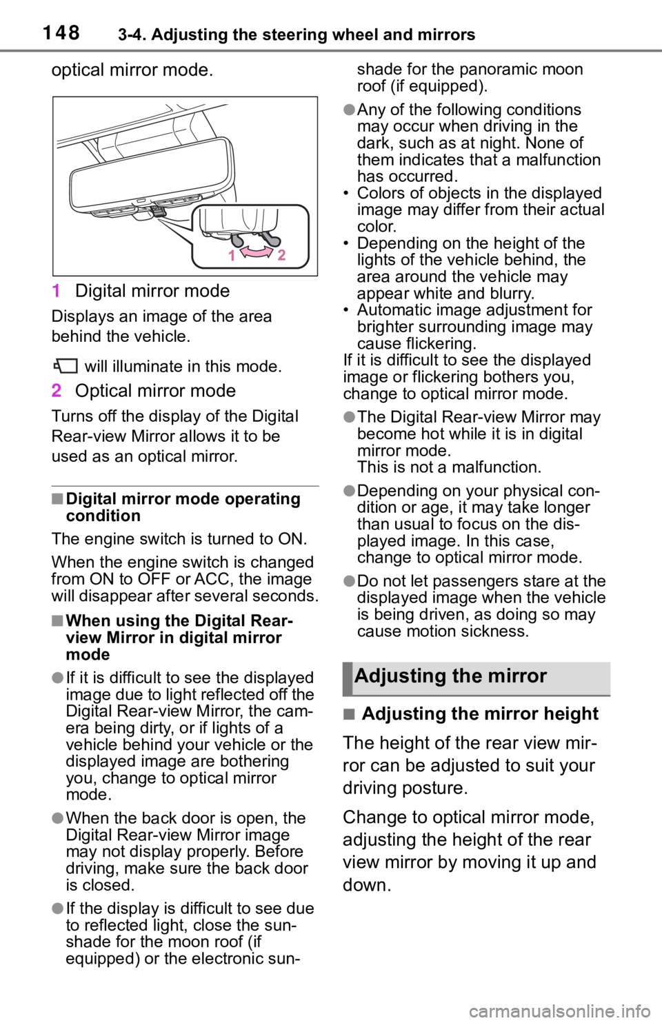
optical mirror mode.
1Digital mirror mode
Displays an image of the area
behind the vehicle.
will illuminate in this mode.
2Optical mirror mode
Turns off the display of the Digital
Rear-view Mirror allows it to be
used as an optical mirror.
■Digital mirror mode operating
condition
The engine switch is turned to ON.
When the engine switch is changed
from ON to OFF or ACC, the image
will disappear afte r several seconds.
■When using the Digital Rear-
view Mirror in digital mirror
mode
●If it is difficult to see the displayed
image due to light reflected off the
Digital Rear-view M irror, the cam-
era being dirty, or if lights of a
vehicle behind your vehicle or the
displayed image are bothering
you, change to optical mirror
mode.
●When the back door is open, the
Digital Rear-view Mirror image
may not display properly. Before
driving, make sure the back door
is closed.
●If the display is difficult to see due
to reflected light, close the sun-
shade for the moon roof (if
equipped) or the electronic sun- shade for the panoramic moon
roof (if equipped).
●Any of the following conditions
may occur when driving in the
dark, such as at night. None of
them indicates that a malfunction
has occurred.
• Colors of objects in the displayed image may differ from their actual
color.
• Depending on the height of the
lights of the vehicle behind, the
area around the vehicle may
appear white and blurry.
• Automatic image adjustment for
brighter surrounding image may
cause flickering.
If it is difficult to see the displayed
image or flickering bothers you,
change to optical mirror mode.
●The Digital Rear-view Mirror may
become hot while it is in digital
mirror mode.
This is not a malfunction.
●Depending on your physical con-
dition or age, it may take longer
than usual to fo cus on the dis-
played image. In this case,
change to optical mirror mode.
●Do not let passengers stare at the
displayed image when the vehicle
is being driven, as doing so may
cause motion sickness.
■Adjusting the mirror height
The height of the rear view mir-
ror can be adjusted to suit your
driving posture.
Change to optical mirror mode,
adjusting the height of the rear
view mirror by moving it up and
down.
Adjusting the mirror
Page 182 of 728
1824-1. Before driving
■Before towing
Check that the fo llowing conditions
are met:
●Ensure that your vehicle’s tires
are properly inflated. ( P.664)
●Trailer tires are inflated according
to the trailer manufacturer’s rec-
ommendation.
●All trailer lights work as required
by law.
●All lights work each time you con-
nect them.
●The trailer ball is set at the proper
height for the coupler on the
trailer.
●The trailer is level when it is
hitched.
Do not drive if th e trailer is not
level, and check for improper
tongue weight, overloading, worn
suspension, or other possible
causes.
●The trailer cargo is securely
loaded.
●The rear view mirr ors conform to
all applicable fede ral, state/provin-
cial or local regulations. If they do
not, install rear view mirrors
appropriate for towing purposes.
Trailer towing
Your vehicle is designed pri-
marily as a passenger-and-
load-carrying vehicle. Tow-
ing a trailer can have an
adverse impact on handling,
performance, braking, dura-
bility, and fuel consumption.
For your safety and the
safety of others, you must
not overload your vehicle or
trailer. You must also
ensure that you are using
appropriate towing equip-
ment, that the towing equip-
ment has been installed
correctly and used prop-
erly, and that you employ
the requisite driving habits.
Vehicle-trailer stability and
braking performance are
affected by trailer stability,
brake performance and set-
ting, trailer brakes, the hitch
and hitch systems (if
equipped).
To tow a trailer safely, use
extreme care and drive the
vehicle in accordance with
your trailer’s characteris-
tics and operating condi-
tions.
Toyota warranties do not
apply to damage or mal-
function caused by towing a
trailer for commercial pur-
poses.
Contact your Toyota dealer for
further information about addi-
tional requirements such as a
towing kit, etc.
Page 189 of 728
1894-1. Before driving
4
Driving
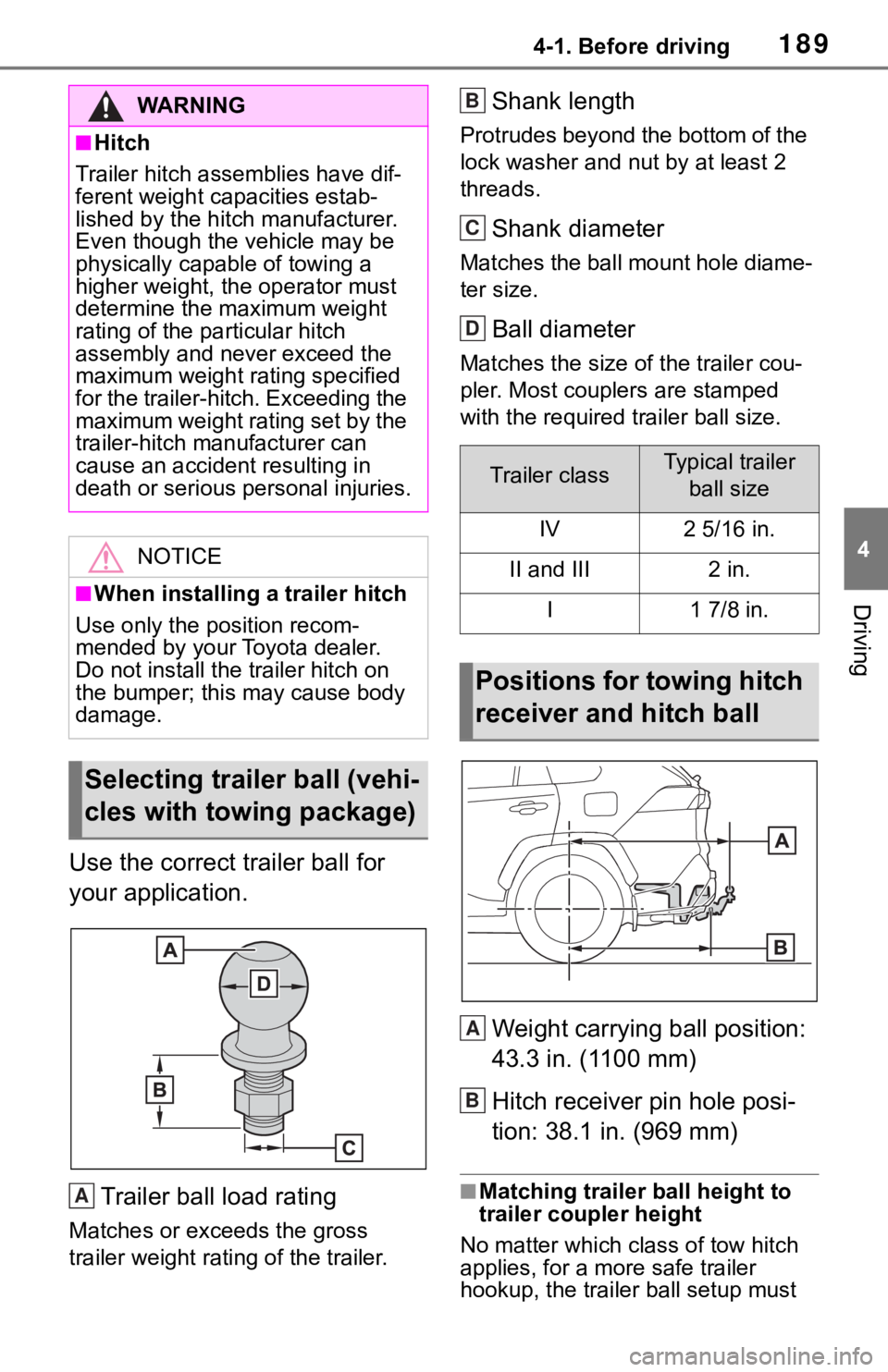
Use the correct trailer ball for
your application.Trailer ball load rating
Matches or exceeds the gross
trailer weight rat ing of the trailer.
Shank length
Protrudes beyond the bottom of the
lock washer and nut by at least 2
threads.
Shank diameter
Matches the ball mount hole diame-
ter size.
Ball diameter
Matches the size of the trailer cou-
pler. Most couplers are stamped
with the required t railer ball size.
Weight carrying ball position:
43.3 in. (1100 mm)
Hitch receiver pin hole posi-
tion: 38.1 in. (969 mm)
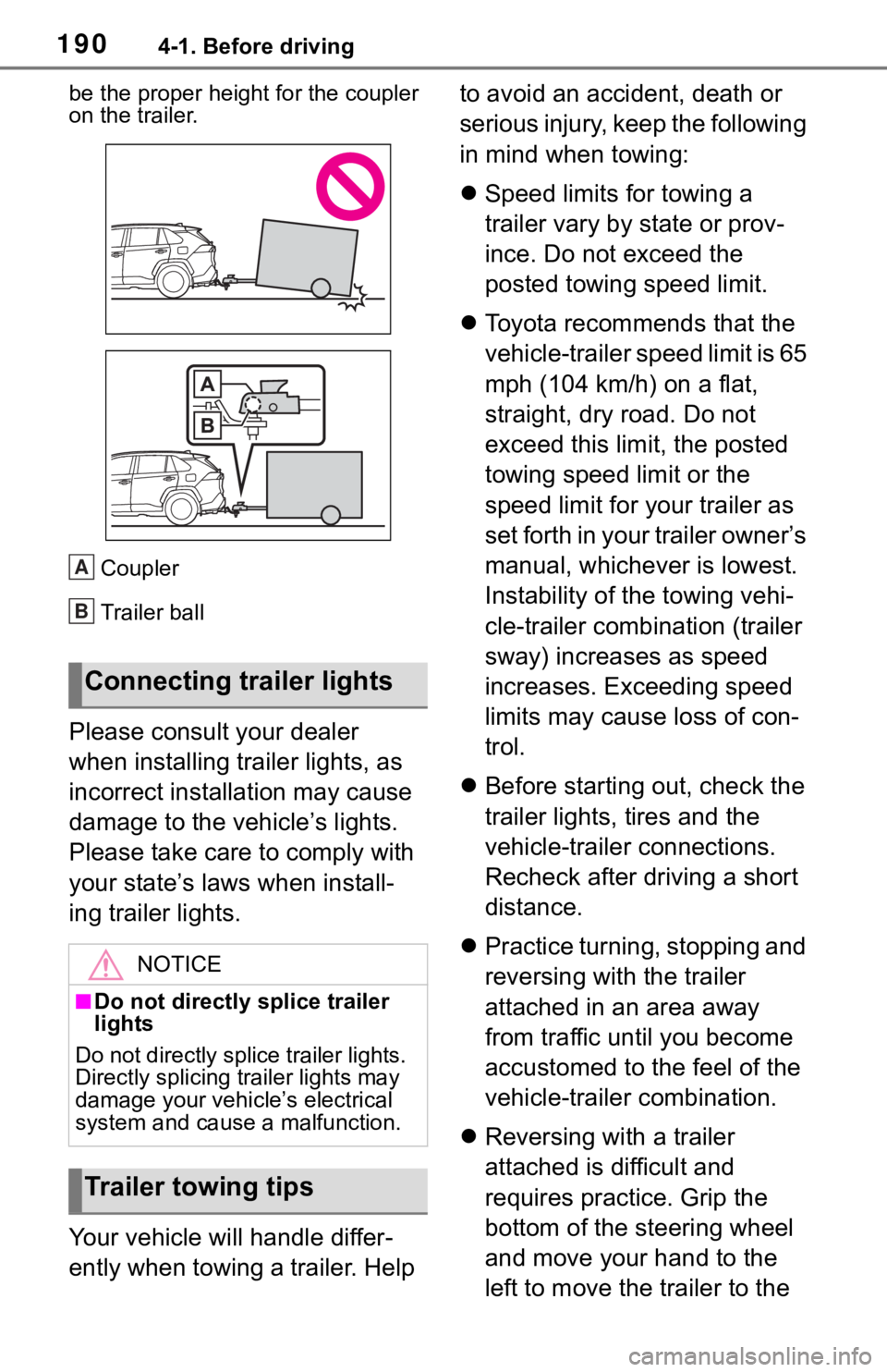
■Matching trailer ball height to
trailer coupler height
No matter wh ich class of tow hitch
applies, for a m ore safe trailer
hookup, the trailer ball setup must
WA R N I N G
■Hitch
Trailer hitch assemblies have dif-
ferent weight capacities estab-
lished by the hitch manufacturer.
Even though the vehicle may be
physically capable of towing a
higher weight, the operator must
determine the maximum weight
rating of the pa rticular hitch
assembly and never exceed the
maximum weight rating specified
for the trailer-hitch. Exceeding the
maximum weight rating set by the
trailer-hitch manufacturer can
cause an accident resulting in
death or serious personal injuries.
NOTICE
■When installing a trailer hitch
Use only the position recom-
mended by your Toyota dealer.
Do not install the trailer hitch on
the bumper; this may cause body
damage.
Selecting trailer ball (vehi-
cles with towing package)
A
Trailer classTypical trailer
ball size
IV2 5/16 in.
II and III2 in.
I1 7/8 in.
Positions for towing hitch
receiver and hitch ball
B
C
D
A
B
Page 190 of 728
1904-1. Before driving
be the proper height for the coupler
on the trailer.Coupler
Trailer ball
Please consult your dealer
when installing trailer lights, as
incorrect installation may cause
damage to the vehicle’s lights.
Please take care to comply with
your state’s laws when install-
ing trailer lights.
Your vehicle will handle differ-
ently when towing a trailer. Help to avoid an accident, death or
serious injury, keep the following
in mind when towing:
Speed limits for towing a
trailer vary by state or prov-
ince. Do not exceed the
posted towing speed limit.
Toyota recommends that the
vehicle-trailer speed limit is 65
mph (104 km/h) on a flat,
straight, dry road. Do not
exceed this limit, the posted
towing speed limit or the
speed limit for your trailer as
set forth in your trailer owner’s
manual, whichever is lowest.
Instability of the towing vehi-
cle-trailer combination (trailer
sway) increases as speed
increases. Exceeding speed
limits may cause loss of con-
trol.
Before starting out, check the
trailer lights, tires and the
vehicle-trailer connections.
Recheck after driving a short
distance.
Practice turning, stopping and
reversing with the trailer
attached in an area away
from traffic until you become
accustomed to the feel of the
vehicle-trailer combination.
Reversing with a trailer
attached is difficult and
requires practice. Grip the
bottom of the steering wheel
and move your hand to the
left to move the trailer to the
Connecting trailer lights
NOTICE
■Do not directly splice trailer
lights
Do not directly splice trailer lights.
Directly splicing trailer lights may
damage your vehicle’s electrical
system and cause a malfunction.
Trailer towing tips
A
B
Page 237 of 728
2374-5. Using the driving support systems
4
Driving
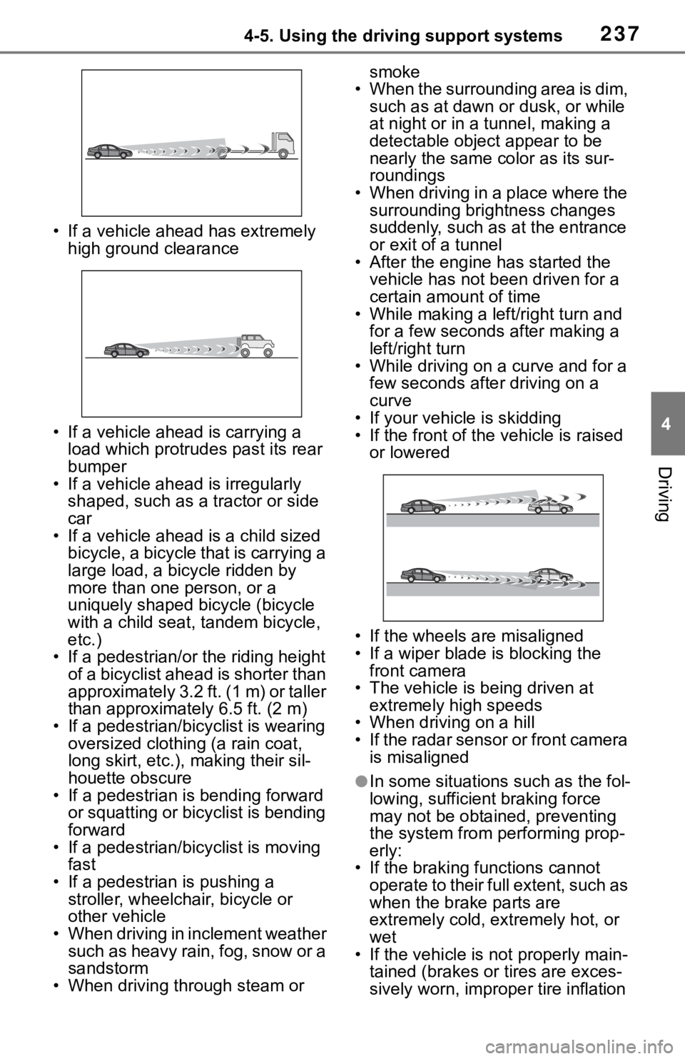
• If a vehicle ahead has extremely high ground clearance
• If a vehicle ahead is carrying a load which protrudes past its rear
bumper
• If a vehicle ahead is irregularly shaped, such as a tractor or side
car
• If a vehicle ahead is a child sized bicycle, a bicycle that is carrying a
large load, a bicycle ridden by
more than one person, or a
uniquely shaped bicycle (bicycle
with a child seat, tandem bicycle,
etc.)
• If a pedestrian/or t he riding height
of a bicyclist ahead is shorter than
approximately 3.2 ft. (1 m) or taller
than approximately 6.5 ft. (2 m)
• If a pedestrian/bicyclist is wearing oversized clothing (a rain coat,
long skirt, etc.), making their sil-
houette obscure
• If a pedestrian is bending forward or squatting or bicyclist is bending
forward
• If a pedestrian/bicyclist is moving fast
• If a pedestrian is pushing a stroller, wheelchair, bicycle or
other vehicle
• When driving in inclement weather such as heavy rain, fog, snow or a
sandstorm
• When driving through steam or smoke
• When the surrounding area is dim, such as at dawn or dusk, or while
at night or in a tunnel, making a
detectable object appear to be
nearly the same co lor as its sur-
roundings
• When driving in a place where the surrounding brightness changes
suddenly, such as at the entrance
or exit of a tunnel
• After the engine has started the vehicle has not been driven for a
certain amount of time
• While making a left/right turn and for a few seconds after making a
left/right turn
• While driving on a curve and for a few seconds afte r driving on a
curve
• If your vehicle is skidding
• If the front of the v ehicle is raised
or lowered
• If the wheels are misaligned
• If a wiper blade is blocking the front camera
• The vehicle is being driven at extremely high speeds
• When driving on a hill
• If the radar sensor or front camera is misaligned
●In some situations such as the fol-
lowing, sufficient braking force
may not be obtained, preventing
the system from p erforming prop-
erly:
• If the braking functions cannot operate to their full extent, such as
when the brake parts are
extremely cold, ext remely hot, or
wet
• If the vehicle is not properly main-
tained (brakes or tires are exces-
sively worn, imprope r tire inflation
Page 268 of 728
2684-5. Using the driving support systems
when driving on the edge of a
lane, and the vehicle in an adja-
cent lane is far away from your
vehicle
• When an accessory (such as a bicycle carrier) is installed to the
rear of the vehicle
• When there is a significant differ- ence in height between your vehi-
cle and the vehicle that enters the
detection area
• Immediately after the BSM func- tion/RCTA function are turned on
• When towing a trailer
●Instances of the BSM function
unnecessarily detecting a vehicle
and/or object may increase in the
following situations:
• When the sensor is misaligned
due to a strong impact to the sen-
sor or its surrounding area
• When the distanc e between your
vehicle and a guar drail, wall, etc.
that enters the detection area is
short
• When driving up and down con- secutive steep inclines, such as
hills, dips in the road, etc.
• When vehicle lanes are narrow, or when driving on the edge of a
lane, and a vehicle traveling in a
lane other than the adjacent lanes
enters the detection area
• When driving on roads with sharp
bends, consecutive curves, or
uneven surfaces
• When the tires are slipping or
spinning
• When the distanc e between your
vehicle and a following vehicle is
short
• When an accessory (such as a bicycle carrier) is installed to the
rear of the vehicle
• When the vehicle throws up water or snow behind.
■Operation of the RCTA
function
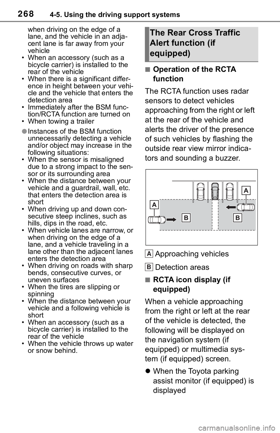
The RCTA function uses radar
sensors to detect vehicles
approaching from the right or left
at the rear of the vehicle and
alerts the driver of the presence
of such vehicles by flashing the
outside rear view mirror indica-
tors and sounding a buzzer.
Approaching vehicles
Detection areas
■RCTA icon display (if
equipped)
When a vehicle approaching
from the right or left at the rear
of the vehicle is detected, the
following will be displayed on
the navigation system (if
equipped) or multimedia sys-
tem (if equipped) screen.
When the Toyota parking
assist monitor (if equipped) is
displayed
The Rear Cross Traffic
Alert function (if
equipped)
A
B