fuel type TOYOTA RAV4 PLUG-IN HYBRID 2023 Owners Manual
[x] Cancel search | Manufacturer: TOYOTA, Model Year: 2023, Model line: RAV4 PLUG-IN HYBRID, Model: TOYOTA RAV4 PLUG-IN HYBRID 2023Pages: 718, PDF Size: 167.55 MB
Page 15 of 718
13Pictorial index
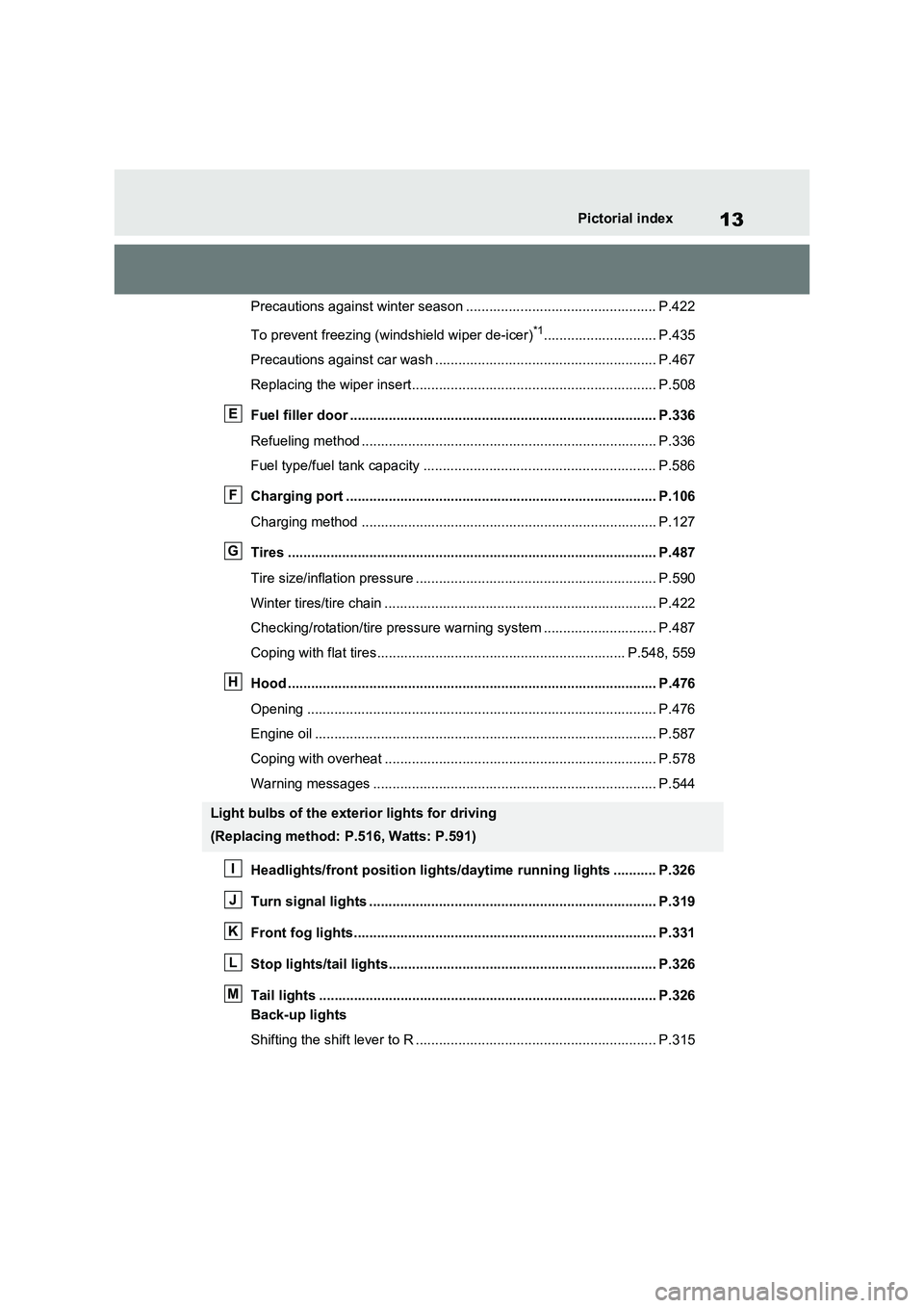
Precautions against winter season ................................................. P.422
To prevent freezing (windshield wiper de-icer)
*1............................. P.435
Precautions against car wash ......................................................... P.467
Replacing the wiper insert............................................................... P.508
Fuel filler door ............................................................................... P.336
Refueling method ............................................................................ P.336
Fuel type/fuel tank capacity ............................................................ P.586
Charging port ................................................................................ P.106
Charging method ............................................................................ P.127
Tires ............................................................................................... P.487
Tire size/inflation pressure .............................................................. P.590
Winter tires/tire chain ...................................................................... P.422
Checking/rotation/tire pressure warning system ............................. P.487
Coping with flat tires................................................................ P.548, 559
Hood ............................................................................................... P.476
Opening .......................................................................................... P.476
Engine oil ........................................................................................ P.587
Coping with overheat ...................................................................... P.578
Warning messages ......................................................................... P.544
Headlights/front position lights/daytime running lights ........... P.326
Turn signal lights .......................................................................... P.319
Front fog lights.............................................................................. P.331
Stop lights/tail lights..................................................................... P.326
Tail lights ....................................................................................... P.326
Back-up lights
Shifting the shift lever to R .............................................................. P.315
Light bulbs of the exterior lights for driving
(Replacing method: P.516, Watts: P.591)
E
F
G
H
I
J
K
L
M
Page 43 of 718
41
1
1-1. For safe use
For safety and security
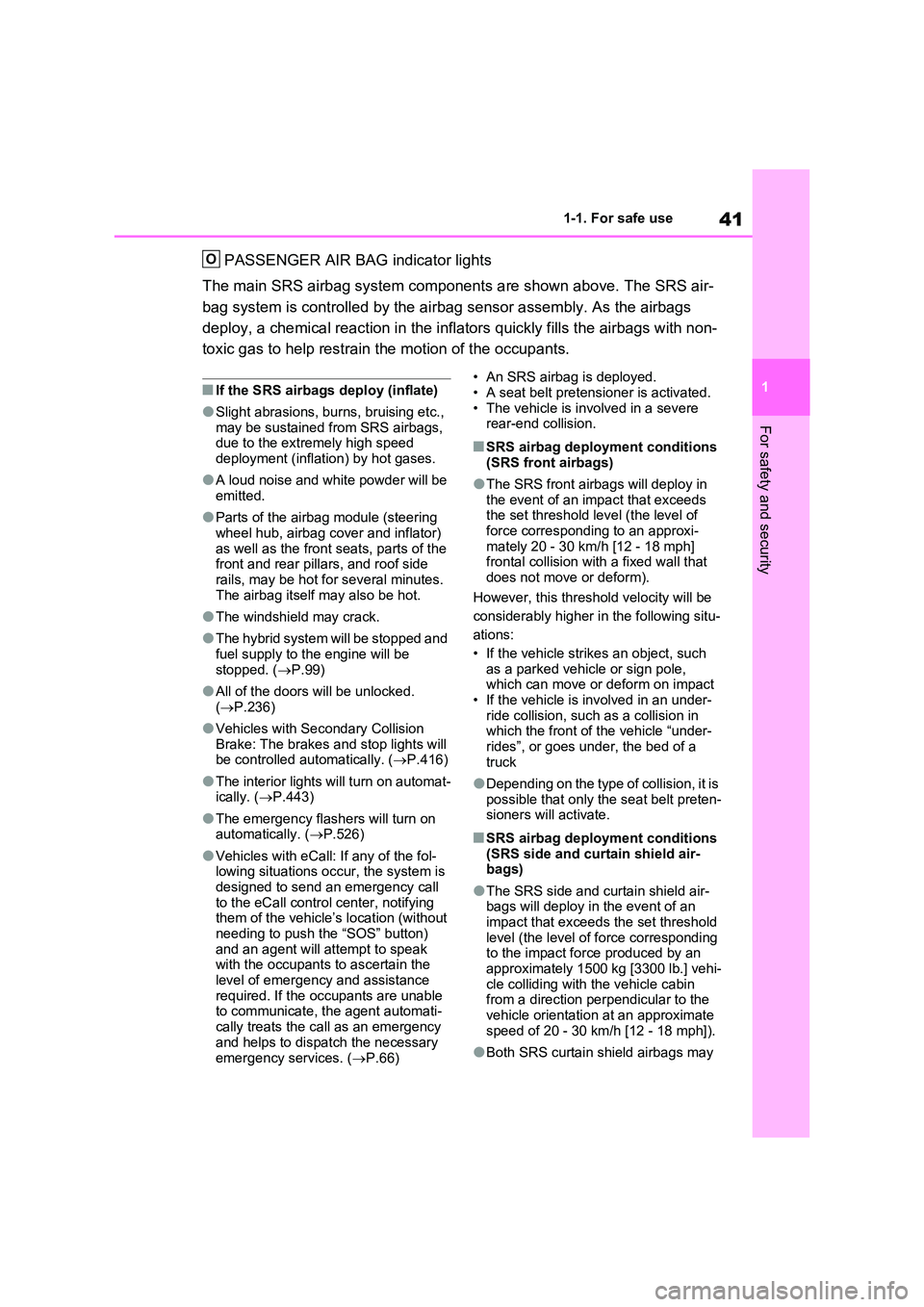
PASSENGER AIR BAG indicator lights
The main SRS airbag system components are shown above. The SRS air-
bag system is controlled by the airbag sensor assembly. As the airbags
deploy, a chemical reaction in the inflators quickly fills the airbags with non-
toxic gas to help restrain the motion of the occupants.
■If the SRS airbags deploy (inflate)
●Slight abrasions, burns, bruising etc., may be sustained from SRS airbags, due to the extremely high speed
deployment (inflation) by hot gases.
●A loud noise and white powder will be
emitted.
●Parts of the airbag module (steering
wheel hub, airbag cover and inflator) as well as the front seats, parts of the front and rear pillars, and roof side
rails, may be hot for several minutes. The airbag itself may also be hot.
●The windshield may crack.
●The hybrid system will be stopped and
fuel supply to the engine will be stopped. ( P.99)
●All of the doors will be unlocked. ( P.236)
●Vehicles with Secondary Collision Brake: The brakes and stop lights will be controlled automatically. ( P.416)
●The interior lights will turn on automat- ically. ( P.443)
●The emergency flashers will turn on automatically. ( P.526)
●Vehicles with eCall: If any of the fol- lowing situations occur, the system is
designed to send an emergency call to the eCall control center, notifying them of the vehicle’s location (without
needing to push the “SOS” button) and an agent will attempt to speak with the occupants to ascertain the
level of emergency and assistance required. If the occupants are unable to communicate, the agent automati-
cally treats the call as an emergency and helps to dispatch the necessary
emergency services. ( P.66)
• An SRS airbag is deployed. • A seat belt pretensioner is activated.
• The vehicle is involved in a severe rear-end collision.
■SRS airbag deployment conditions
(SRS front airbags)
●The SRS front airbags will deploy in
the event of an impact that exceeds the set threshold level (the level of force corresponding to an approxi-
mately 20 - 30 km/h [12 - 18 mph] frontal collision with a fixed wall that does not move or deform).
However, this threshold velocity will be
considerably higher in the following situ-
ations:
• If the vehicle strikes an object, such as a parked vehicle or sign pole, which can move or deform on impact
• If the vehicle is involved in an under- ride collision, such as a collision in which the front of the vehicle “under-
rides”, or goes under, the bed of a truck
●Depending on the type of collision, it is possible that only the seat belt preten-sioners will activate.
■SRS airbag deployment conditions
(SRS side and curtain shield air- bags)
●The SRS side and curtain shield air-bags will deploy in the event of an impact that exceeds the set threshold
level (the level of force corresponding to the impact force produced by an approximately 1500 kg [3300 lb.] vehi-
cle colliding with the vehicle cabin from a direction perpendicular to the vehicle orientation at an approximate
speed of 20 - 30 km/h [12 - 18 mph]).
●Both SRS curtain shield airbags may
O
Page 107 of 718
105
2 2-1. Plug-in hybrid system
Plug-in hybrid system
A pressure level 50 kPa (0.5 kgf/cm2 or
bar, 7 psi) lower than the specified
value will cause a worsening of several
percentage points.
■When driving on highways,
use the EV/HV mode selection
switch to drive in HV mode
The power consumption will
increase significantly if the vehicle
is driven in EV mode on highways.
■Do not load unnecessary
objects in the vehicle
Driving with objects weighing 100
kg (220 lb.) in the vehicle will
worsen the electrical and fuel effi-
ciency by approximately 3%.
Air resistance also greatly affects
electrical and fuel efficiency.
Remove any exterior accessories
such as a roof luggage carrier when
they are not being used.
The running resistance of snow
tires is high and they will worsen
electrical and fuel efficiency.
Replace them with standard tires
as soon as they are no longer
needed.
■Know your vehicle’s electrical
and fuel efficiency
If you know your vehicle’s daily
electrical and fuel efficiency, you
will understand the benefits of Eco
drive.
Use the Power Consumption/Fuel
Economy, ECO Accelerator Guid-
ance/“Eco Score” and other data
displayed on the multi-information display.
The following indicate that charging
has been carried out properly.
The charging indicator of the
charging port turns off
“Charging Complete” is dis-
played on the multi-information
display when a door is opened
with the power switch off
(P.131)
Regardless of the type of power
source or whether the charging
schedule function is used, charging
is completed if the above can be
confirmed.
Charging-related messages: P.172
Display when charging is
completed
Page 189 of 718
187
3
3-1. Instrument cluster
Vehicle status information and indicators
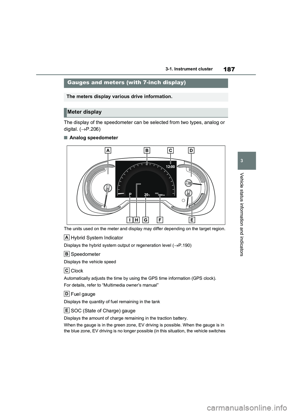
The display of the speedometer can be selected from two types, analog or
digital. ( P.206)
■Analog speedometer
The units used on the meter and display may differ depending on the target region.
Hybrid System Indicator
Displays the hybrid system output or regeneration level (P.190)
Speedometer
Displays the vehicle speed
Clock
Automatically adjusts the time by using the GPS time information (GPS clock).
For details, refer to “Multimedia owner’s manual”
Fuel gauge
Displays the quantity of fuel remaining in the tank
SOC (State of Charge) gauge
Displays the amount of charge remaining in the traction battery.
When the gauge is in the green zone, EV driving is possible. When the gauge is in
the blue zone, EV driving is no longer possible (in this situation, the vehicle switches
Gauges and meters (with 7-inch display)
The meters display various drive information.
Meter display
A
B
C
D
E
Page 197 of 718
195
3 3-1. Instrument cluster
Vehicle status information and indicators
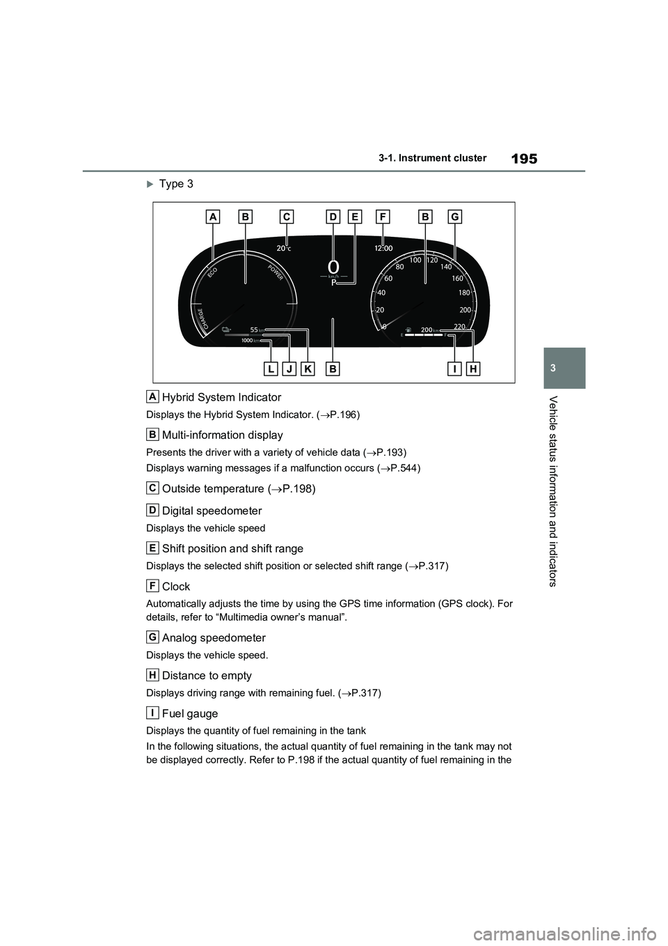
Type 3
Hybrid System Indicator
Displays the Hybrid System Indicator. (P.196)
Multi-information display
Presents the driver with a variety of vehicle data (P.193)
Displays warning messages if a malfunction occurs (P.544)
Outside temperature (P.198)
Digital speedometer
Displays the vehicle speed
Shift position and shift range
Displays the selected shift position or selected shift range (P.317)
Clock
Automatically adjusts the time by using the GPS time information (GPS clock). For
details, refer to “Multimedia owner’s manual”.
Analog speedometer
Displays the vehicle speed.
Distance to empty
Displays driving range with remaining fuel. (P.317)
Fuel gauge
Displays the quantity of fuel remaining in the tank
In the following situations, the actual quantity of fuel remaining in the tank may not
be displayed correctly. Refer to P.198 if the actual quantity of fuel remaining in the
A
B
C
D
E
F
G
H
I
Page 198 of 718
1963-1. Instrument cluster
tank is not displayed correctly.
• A small amount of fuel is added.
• Fuel is added with the fuel gauge near or at “F”.
• The vehicle is stopped on an uneven surface, such as a slope.
• The vehicle is driven on a slope or around a curve.
SOC (State of Charge) gauge
Displays the amount of charge remaining in the traction battery. (P.197)
EV driving range
Displays the EV driving range with charge remaining in the hybrid battery (traction
battery).
Odometer and trip meter display (P.187)
■The meters and display illuminate
when
The power switch is in ON.
■Engine speed
On hybrid vehicles, engine speed is pre-
cisely controlled in order to help improve
fuel efficiency and reduce exhaust emis-
sions etc.
There are times when the engine speed
that is displayed may differ even when
vehicle operation and driving conditions
are the same.
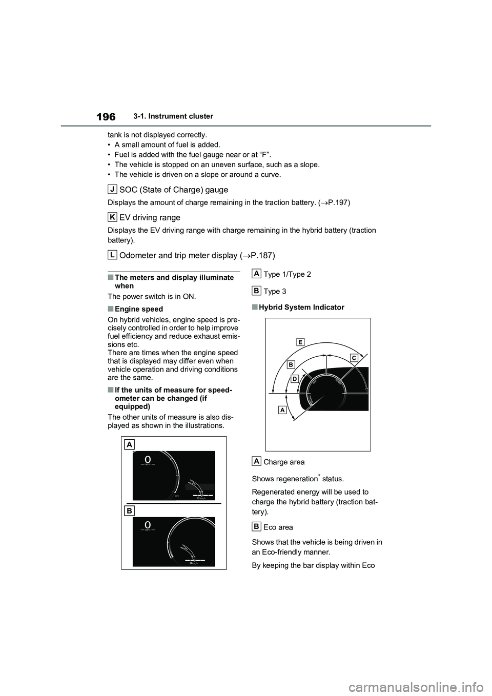
■If the units of measure for speed-
ometer can be changed (if
equipped)
The other units of measure is also dis-
played as shown in the illustrations.Type 1/Type 2
Type 3
■Hybrid System Indicator
Charge area
Shows regeneration
* status.
Regenerated energy will be used to
charge the hybrid battery (traction bat-
tery).
Eco area
Shows that the vehicle is being driven in
an Eco-friendly manner.
By keeping the bar display within Eco
J
K
L
A
B
A
B
Page 201 of 718
199
3
3-1. Instrument cluster
Vehicle status information and indicators
■Display items
Odometer
Displays the total distance the vehicle
has been driven.
Trip meter A/trip meter B
Displays the distance the vehicle has
been driven since the meter was last
reset. Trip meters A and B can be used
to record and display different dis-
tances independently.
■Changing the display
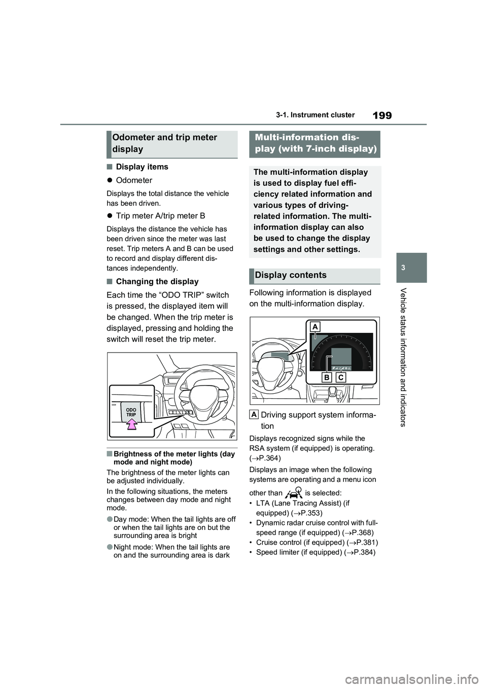
Each time the “ODO TRIP” switch
is pressed, the displayed item will
be changed. When the trip meter is
displayed, pressing and holding the
switch will reset the trip meter.
■Brightness of the meter lights (day mode and night mode)
The brightness of the meter lights can
be adjusted individually.
In the following situations, the meters
changes between day mode and night mode.
●Day mode: When the tail lights are off or when the tail lights are on but the surrounding area is bright
●Night mode: When the tail lights are on and the surrounding area is dark
Following information is displayed
on the multi-information display.
Driving support system informa-
tion
Displays recognized signs while the
RSA system (if equipped) is operating.
( P.364)
Displays an image when the following
systems are operating and a menu icon
other than is selected:
• LTA (Lane Tracing Assist) (if
equipped) ( P.353)
• Dynamic radar cruise control with full-
speed range (if equipped) ( P.368)
• Cruise control (if equipped) ( P.381)
• Speed limiter (if equipped) ( P.384)
Odometer and trip meter
display
Multi-information dis-
play (with 7-inch display)
The multi-information display
is used to display fuel effi-
ciency related information and
various types of driving-
related information. The multi-
information display can also
be used to change the display
settings and other settings.
Display contents
A
Page 206 of 718
2043-1. Instrument cluster
tion rate of the electricity when EV driv-
ing is performed and equivalent to the
fuel consumption for the gasoline vehi-
cles. For this vehicle, electricity con-
sumed per 100 km (“kWh/100 km”) is
displayed as electricity consumption on
each screen.
■EV driving range
●When the air conditioning system is
operating, is displayed next to
the EV driving range and the EV driv-
ing range with the air conditioning sys-
tem on is displayed.
●The EV driving range may shorten
even when not driving due to power
consumption by the system.
●For details, refer to “EV driving range”
(P.103)
■Distance to empty
●This distance is computed based on
your average fuel consumption. As a
result, the actual distance that can be
driven may differ from that displayed.
●When only a small amount of fuel is
added to the tank, the display may not
be updated. When refueling, turn the
power switch off. If the vehicle is refu-
eled without turning the power switch
off, the display may not be updated.
●When “Refuel” is displayed, the
remaining fuel amount is low and the
distance that can be driven with the
remaining fuel cannot be calculated.
Refuel immediately.
■ECO Accelerator Guidance/“Eco
Score” will not operate when
The ECO Accelerator Guidance/“Eco
Score” will not operate in the following
situations:
●The Hybrid System Indicator is not
operating.
●The vehicle is being driven using the
dynamic radar cruise control with full-
speed range.
■Driving support system infor-
mation display
Select to display the operational
status of the following systems:
LTA (Lane Tracing Assist)
*
(P.353)
Dynamic radar cruise control
with full-speed range
* (P.368)
Cruise control
* (P.381)
Speed limiter
* (P.384)
*: If equipped
■Navigation system-linked dis-
play (if equipped)
Select to display the following navi-
gation system-linked information.
Route guidance
Compass display
Select to enable selection of an
audio source or track on the dis-
play.
■Drive information
2 items that are selected using the
“Drive Info Items” setting (average
speed, distance and total time) can
be displayed vertically.
The displayed information changes
according to the “Drive Info Type”
Driving support system
information display
Audio system-linked display
Vehicle information display
Page 210 of 718
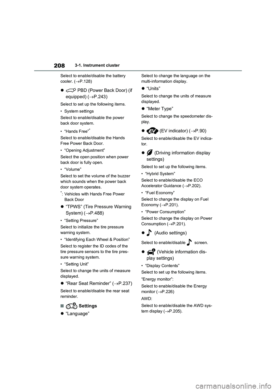
2083-1. Instrument cluster
Select to enable/disable the battery
cooler. (P.128)
PBD (Power Back Door) (if
equipped) (P.243)
Select to set up the following items.
•System settings
Select to enable/disable the power
back door system.
•“Hands Free”
*
Select to enable/disable the Hands
Free Power Back Door.
• “Opening Adjustment”
Select the open position when power
back door is fully open.
•“Volume”
Select to set the volume of the buzzer
which sounds when the power back
door system operates.
*: Vehicles with Hands Free Power
Back Door
“TPWS” (Tire Pressure Warning
System) (P.488)
• “Setting Pressure”
Select to initialize the tire pressure
warning system.
• “Identifying Each Wheel & Position”
Select to register the ID codes of the
tire pressure sensors to the tire pres-
sure warning system.
•“Setting Unit”
Select to change the units of measure
displayed.
“Rear Seat Reminder” (P.237)
Select to enable/disable the rear seat
reminder.
■ Settings
“Language”
Select to change the language on the
multi-information display.
“Units”
Select to change the units of measure
displayed.
“Meter Type”
Select to change the speedometer dis-
play.
(EV indicator) (P.90)
Select to enable/disable the EV indica-
tor.
(Driving information display
settings)
Select to set up the following items.
•“Hybrid System”
Select to enable/disable the ECO
Accelerator Guidance (P.202).
• “Fuel Economy”
Select to change the display on Fuel
Economy (P.201).
• “Power Consumption”
Select to change the display on Power
Consumption (P.201).
(Audio settings)
Select to enable/disable screen.
(Vehicle information dis-
play settings)
• “Display Contents”
Select to set up the following items.
“Energy monitor”:
Select to enable/disable the Energy
monitor (P.226)
AWD:
Select to enable/disable the AWD sys-
tem display (P.205).
Page 213 of 718
211
3 3-1. Instrument cluster
Vehicle status information and indicators
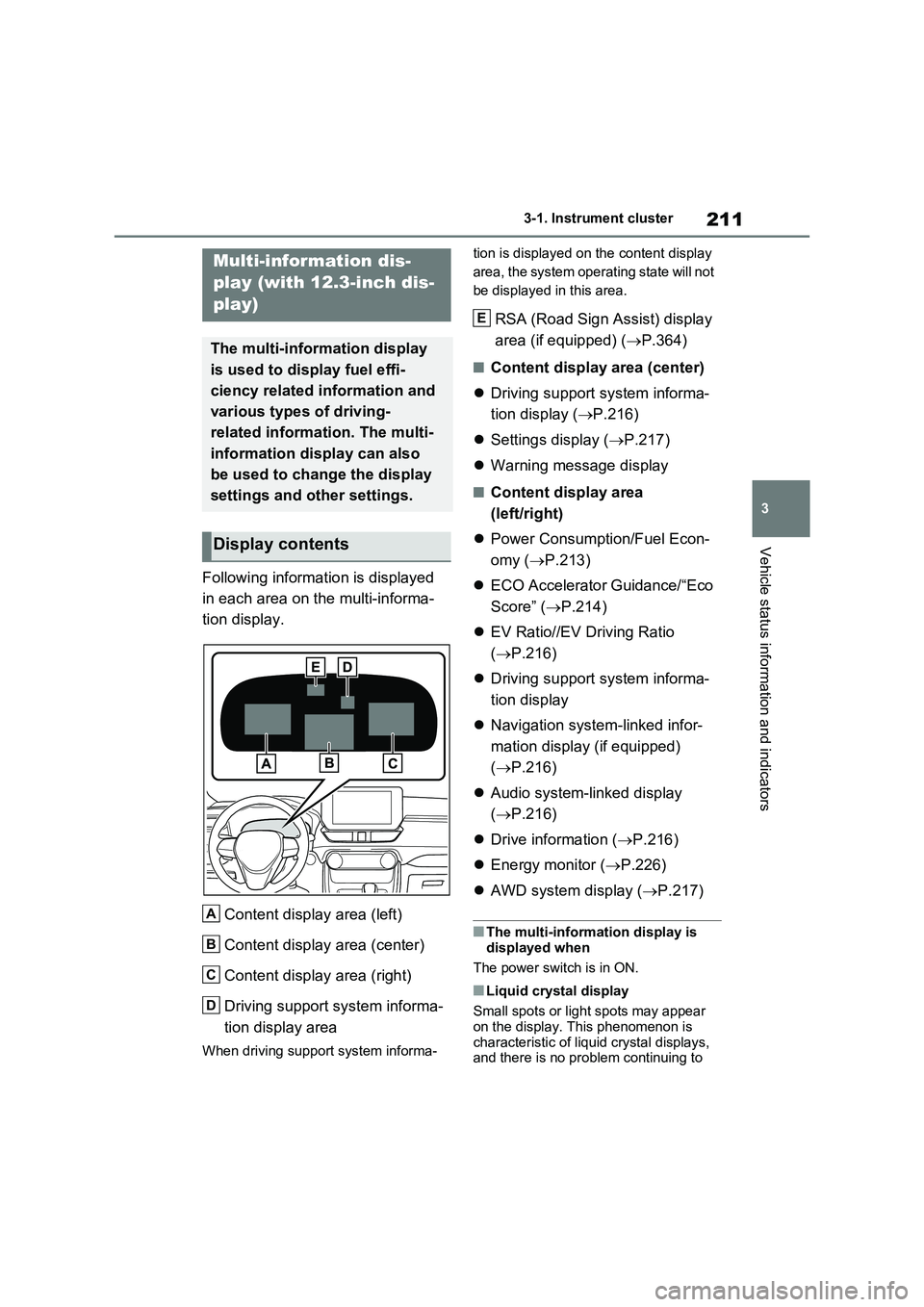
Following information is displayed
in each area on the multi-informa-
tion display.
Content display area (left)
Content display area (center)
Content display area (right)
Driving support system informa-
tion display area
When driving support system informa-tion is displayed on the content display
area, the system operating state will not
be displayed in this area.
RSA (Road Sign Assist) display
area (if equipped) (P.364)
■Content display area (center)
Driving support system informa-
tion display (P.216)
Settings display (P.217)
Warning message display
■Content display area
(left/right)
Power Consumption/Fuel Econ-
omy (P.213)
ECO Accelerator Guidance/“Eco
Score” (P.214)
EV Ratio//EV Driving Ratio
(P.216)
Driving support system informa-
tion display
Navigation system-linked infor-
mation display (if equipped)
(P.216)
Audio system-linked display
(P.216)
Drive information (P.216)
Energy monitor (P.226)
AWD system display (P.217)
■The multi-information display is
displayed when
The power switch is in ON.
■Liquid crystal display
Small spots or light spots may appear
on the display. This phenomenon is
characteristic of liquid crystal displays,
and there is no problem continuing to
Multi-information dis-
play (with 12.3-inch dis-
play)
The multi-information display
is used to display fuel effi-
ciency related information and
various types of driving-
related information. The multi-
information display can also
be used to change the display
settings and other settings.
Display contents
A
B
C
D
E