torque TOYOTA RAV4 PLUG-IN HYBRID 2023 Owners Manual
[x] Cancel search | Manufacturer: TOYOTA, Model Year: 2023, Model line: RAV4 PLUG-IN HYBRID, Model: TOYOTA RAV4 PLUG-IN HYBRID 2023Pages: 718, PDF Size: 167.55 MB
Page 102 of 718
1002-1. Plug-in hybrid system
stops the fuel pump to minimize the
risk of electrocution and fuel leak-
age.
If the emergency shut off system
activates, your vehicle will not
restart. To restart the hybrid sys-
tem, contact any authorized Toyota
retailer or Toyota authorized
repairer, or any reliable repairer.
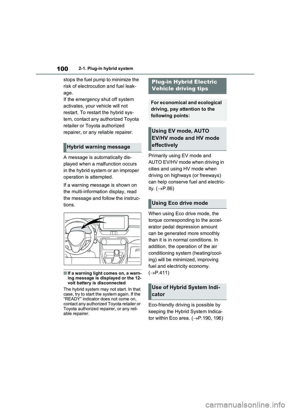
A message is automatically dis-
played when a malfunction occurs
in the hybrid system or an improper
operation is attempted.
If a warning message is shown on
the multi-information display, read
the message and follow the instruc-
tions.
■If a warning light comes on, a warn-
ing message is displayed or the 12-
volt battery is disconnected
The hybrid system may not start. In that
case, try to start the system again. If the
“READY” indicator does not come on,
contact any authorized Toyota retailer or
Toyota authorized repairer, or any reli-
able repairer.
Primarily using EV mode and
AUTO EV/HV mode when driving in
cities and using HV mode when
driving on highways (or freeways)
can help conserve fuel and electric-
ity. (P.86)
When using Eco drive mode, the
torque corresponding to the accel-
erator pedal depression amount
can be generated more smoothly
than it is in normal conditions. In
addition, the operation of the air
conditioning system (heating/cool-
ing) will be minimized, improving
fuel and electricity economy.
(P.411)
Eco-friendly driving is possible by
keeping the Hybrid System Indica-
tor within Eco area. (P.190, 196)
Hybrid warning message
Plug-in Hybrid Electric
Vehicle driving tips
For economical and ecological
driving, pay attention to the
following points:
Using EV mode, AUTO
EV/HV mode and HV mode
effectively
Using Eco drive mode
Use of Hybrid System Indi-
cator
Page 106 of 718
1042-1. Plug-in hybrid system
■When starting off, depress the
accelerator pedal smoothly to
accelerate
As a guide, accelerate up to
approximately 20 km/h (12mph) in
the first 5 seconds.
Electrical and fuel efficiency can be
improved just by using the ECO
Accelerator Guidance displayed on
the multi-information display and
taking care to start off gently.
(P.202)
When the driving mode is set to Eco
drive mode, depressing the accelerator
pedal generates smooth torque that
makes it easier to operate the accelera-
tor gently.
■Maintain sufficient vehicle-to-
vehicle distance and do not
accelerate or decelerate
unnecessarily
Try to maintain a fixed speed while
driving. Driving at a short vehicle-
to-vehicle distance will result in
repeating wasteful acceleration and
deceleration, which will worsen the
electrical and fuel efficiency.
■Release the accelerator pedal
early before stopping the vehi-
cle, such as at a traffic light
The regenerative brake will operate
to convert the kinetic energy of the
vehicle into electrical energy, which
will charge the hybrid battery (trac-
tion battery).
The regeneration status can be
checked from the Hybrid System
Indicator. (P.190)When the brake pedal is depressed
lightly during deceleration, the
regeneration amount increases,
enabling more electrical energy to
be recovered.
If the brake pedal is depressed too
strongly, the recovered amount indica-
tor will reach the maximum level and
the upper limit of the recoverable
energy will be exceeded. Therefore, be
sure to operate the brake pedal early.
■Use the air conditioning sys-
tem appropriately, and also
utilize the heated steering
wheel (if equipped) and seat
heaters
In EV mode, the vehicle is cooled
and heated by electrical energy.
(Except in extremely cold tempera-
tures of approximately -10°C (14°F)
or less.)
Preventing excessive cooling or
heating of the vehicle will reduce
power consumption and improve
electrical efficiency.
The heated steering wheel (if
equipped) and seat heaters are effi-
cient heating device that directly
warm the body using less electric
power.
When used together with the air condi-
tioning system, a low temperature set-
ting can be used to improve electrical
and fuel efficiency.
■Check the tire pressure
If the tire pressure is lower than the
specified value, it will worsen the
electrical and fuel efficiency.
Page 207 of 718
205
3 3-1. Instrument cluster
Vehicle status information and indicators
setting (since the system was
started or between resets).
(P.206)
Use the displayed information as a ref-
erence only.
Following items will be displayed.
“Trip”
• “Average Speed”: Displays the aver-
age vehicle speed since hybrid sys-
tem start
*
• “Distance”: Displays the distance
driven since hybrid system start*
• “Total Time”: Displays the elapsed
time since hybrid system start*
*
: These items are reset each time the
hybrid system stops.
“Total”
• “Average Speed”: Displays the aver-
age vehicle speed since the display
was reset
*
• “Distance”: Displays the distance
driven since the display was reset*
• “Total Time”: Displays the elapsed
time since the display was reset*
*
: To reset, display the desired item and
press and hold .
■Energy monitor
P.226
■Tire pressure
P.488
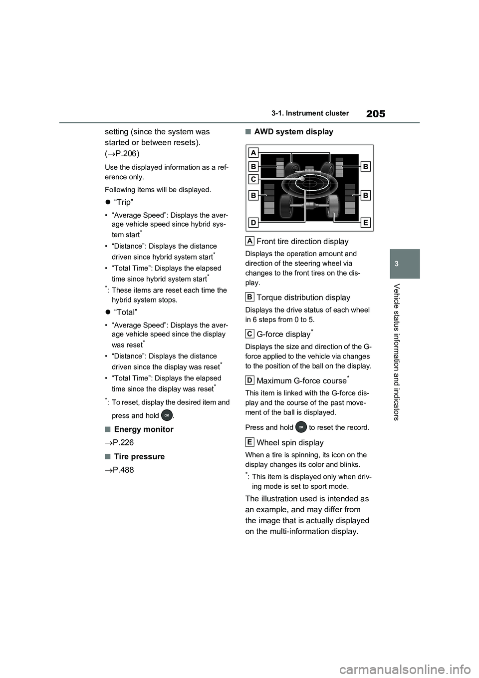
■AWD system display
Front tire direction display
Displays the operation amount and
direction of the steering wheel via
changes to the front tires on the dis-
play.
Torque distribution display
Displays the drive status of each wheel
in 6 steps from 0 to 5.
G-force display*
Displays the size and direction of the G-
force applied to the vehicle via changes
to the position of the ball on the display.
Maximum G-force course*
This item is linked with the G-force dis-
play and the course of the past move-
ment of the ball is displayed.
Press and hold to reset the record.
Wheel spin display
When a tire is spinning, its icon on the
display changes its color and blinks.
*: This item is displayed only when driv-
ing mode is set to sport mode.
The illustration used is intended as
an example, and may differ from
the image that is actually displayed
on the multi-information display.
A
B
C
D
E
Page 219 of 718
217
3 3-1. Instrument cluster
Vehicle status information and indicators
display was reset*
• “Distance”: Displays the distance
driven since the display was
reset
*
• “Total Time”: Displays the
elapsed time since the display
was reset
*
*: To reset, display the desired item and
press and hold .
P.226
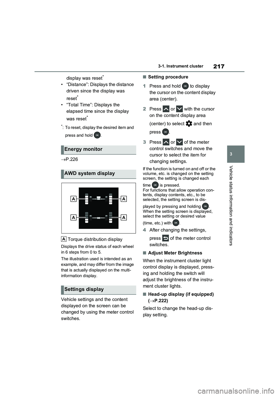
Torque distribution display
Displays the drive status of each wheel
in 6 steps from 0 to 5.
The illustration used is intended as an
example, and may differ from the image
that is actually displayed on the multi-
information display.
Vehicle settings and the content
displayed on the screen can be
changed by using the meter control
switches.
■Setting procedure
1Press and hold to display
the cursor on the content display
area (center).
2Press or with the cursor
on the content display area
(center) to select and then
press .
3Press or of the meter
control switches and move the
cursor to select the item for
changing settings.
If the function is turned on and off or the
volume, etc. is changed on the setting
screen, the setting is changed each
time is pressed.
For functions that allow operation con-
tents, display contents, etc., to be
selected, the setting screen is dis-
played by pressing and holding .
When the setting screen is displayed,
select the setting or desired value
(time, etc.) with .
4After changing the settings,
press of the meter control
switches.
■Adjust Meter Brightness
When the instrument cluster light
control display is displayed, press-
ing and holding the switch will
adjust the brightness of the instru-
ment cluster lights.
■Head-up display (if equipped)
(P.222)
Select to change the head-up dis-
play setting.
Energy monitor
AWD system display
Settings display
A
Page 348 of 718
3465-5. Using the driving support systems
■Enabling/disabling the pre-col-
lision system
The pre-collision system can be
enabled/disabled on the screen
( P.206, 217) of the multi-informa-
tion display.
The system is automatically enabled
each time the power switch is turned to
ON.
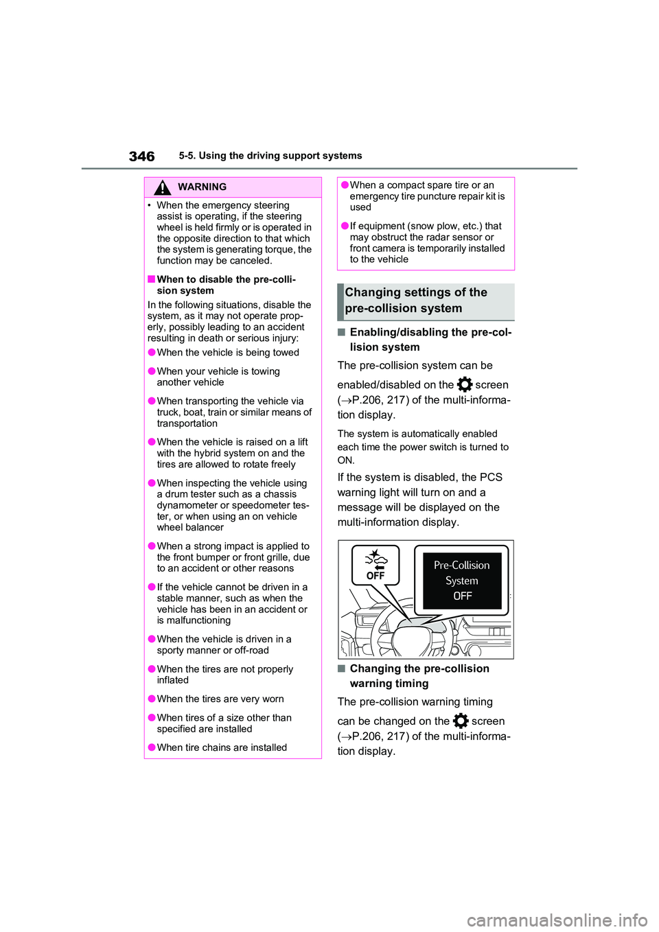
If the system is disabled, the PCS
warning light will turn on and a
message will be displayed on the
multi-information display.
■Changing the pre-collision
warning timing
The pre-collision warning timing
can be changed on the screen
( P.206, 217) of the multi-informa-
tion display.
WARNING
• When the emergency steering assist is operating, if the steering
wheel is held firmly or is operated in the opposite direction to that which the system is generating torque, the
function may be canceled.
■When to disable the pre-colli-
sion system
In the following situations, disable the system, as it may not operate prop-
erly, possibly leading to an accident resulting in death or serious injury:
●When the vehicle is being towed
●When your vehicle is towing another vehicle
●When transporting the vehicle via truck, boat, train or similar means of
transportation
●When the vehicle is raised on a lift
with the hybrid system on and the tires are allowed to rotate freely
●When inspecting the vehicle using a drum tester such as a chassis dynamometer or speedometer tes-
ter, or when using an on vehicle wheel balancer
●When a strong impact is applied to the front bumper or front grille, due to an accident or other reasons
●If the vehicle cannot be driven in a stable manner, such as when the
vehicle has been in an accident or is malfunctioning
●When the vehicle is driven in a sporty manner or off-road
●When the tires are not properly inflated
●When the tires are very worn
●When tires of a size other than
specified are installed
●When tire chains are installed
●When a compact spare tire or an emergency tire puncture repair kit is used
●If equipment (snow plow, etc.) that may obstruct the radar sensor or
front camera is temporarily installed to the vehicle
Changing settings of the
pre-collision system
Page 413 of 718
411
5
5-5. Using the driving support systems
Driving
abled.
• The collision becomes avoidable with normal brake operation.• A vehicle is no longer approaching
from the right or left at the rear of the vehicle.
●Brake control• The Parking Support Brake is dis-abled.
• Approximately 2 seconds have elapsed since the vehicle was stopped by brake control.
• The brake pedal is depressed after the vehicle is stopped by brake con-trol.
• A vehicle is no longer approaching from the right or left at the rear of the vehicle.
■Detection area of the Parking Sup-
port Brake function (rear-crossing vehicles)
The detection area of the Parking Sup-
port Brake function (rear-crossing vehi- cles) differs from the detection area of the RCTA function ( P.392). Therefore,
even if the RCTA function detects a vehicle and provides an alert, the Park-ing Support Brake function (rear-cross-
ing vehicles) may not start operating.
■Situations in which the system may not operate properly
P.393
■Situations in which the system may
operate even if there is no possibil- ity of a collision
P.394
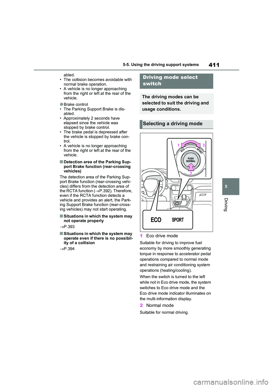
1Eco drive mode
Suitable for driving to improve fuel
economy by more smoothly generating
torque in response to accelerator pedal
operations compared to normal mode
and restraining air conditioning system
operations (heating/cooling).
When the switch is turned to the left
while not in Eco drive mode, the system
switches to Eco drive mode and the
Eco drive mode indicator illuminates on
the multi-information display.
2 Normal mode
Suitable for normal driving.
Driving mode select
switch
The driving modes can be
selected to suit the driving and
usage conditions.
Selecting a driving mode
Page 418 of 718
4165-5. Using the driving support systems
■VSC+ (Vehicle Stability Con-
trol+)
Provides cooperative control of the
ABS, TRC, VSC and EPS.
Helps to maintain directional stabil-
ity when swerving on slippery road
surfaces by controlling steering per-
formance.
■Trailer Sway Control
Helps the driver to control trailer
sway by selectively applying brake
pressure for individual wheels and
reducing driving torque when trailer
sway is detected.
■TRC (Traction Control)
Helps to maintain drive power and
prevent the drive wheels from spin-
ning when starting the vehicle or
accelerating on slippery roads
■Active Cornering Assist (ACA)
Helps to prevent the vehicle from
drifting to the outer side by perform-
ing inner wheel brake control when
attempting to accelerate while turn-
ing
■Hill-start assist control
Helps to reduce the backward
movement of the vehicle when
starting on an uphill
■EPS (Electric Power Steering)
Employs an electric motor to
reduce the amount of effort needed
to turn the steering wheel.
■E-Four (Electronic On-Demand
AWD system)
Automatically controls the drive
system such as to front-wheel drive
or AWD (all wheel drive) according
to various running conditions
including normal driving, during cor-
nering, on a uphill, when starting
off, during acceleration, on a slip-
pery roads due to snow or rain,
thus contributing to stable
operability and driving stability.
■Emergency brake signal
When the brakes are applied sud-
denly, the emergency flashers
automatically flash to alert the vehi-
cle behind.
■The Secondary Collision
Brake (if equipped)
When the SRS airbag sensor
detects a collision and the system
operates, the brakes and brake
lights are automatically controlled
to reduce the vehicle speed and
help reduce the possibility of further
damage due to a secondary colli-
sion.
■When the TRC/VSC/ABS/Trail
Mode/Trailer Sway Control systems
are operating
The slip indicator light will flash while the
TRC/VSC/ABS/Trail Mode/Trailer Sway
Control systems are operating.
Page 565 of 718
563
8
8-2. Steps to take in an emergency
When trouble arises
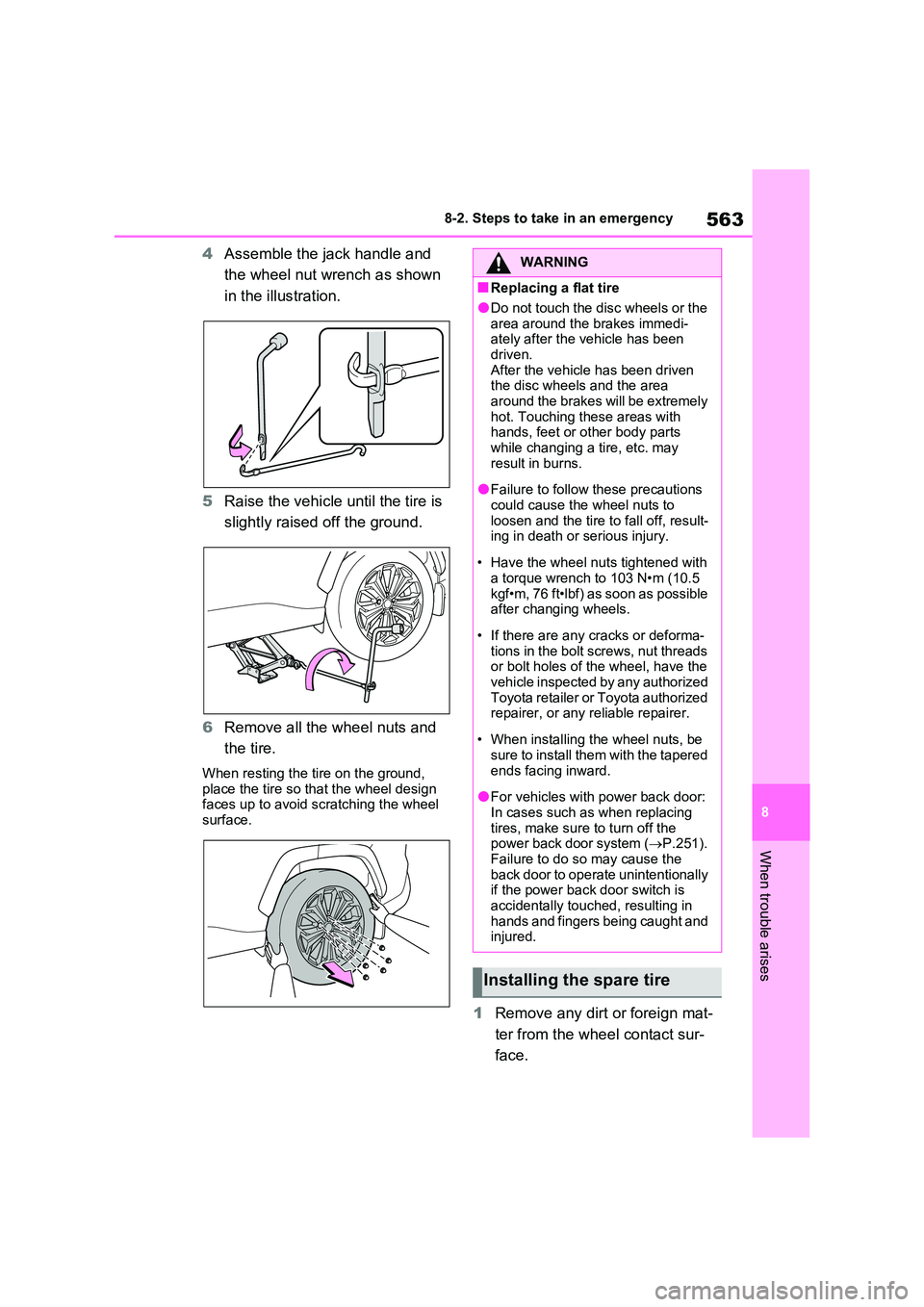
4 Assemble the jack handle and
the wheel nut wrench as shown
in the illustration.
5 Raise the vehicle until the tire is
slightly raised off the ground.
6 Remove all the wheel nuts and
the tire.
When resting the tire on the ground,
place the tire so that the wheel design faces up to avoid scratching the wheel surface.
1 Remove any dirt or foreign mat-
ter from the wheel contact sur-
face.
WARNING
■Replacing a flat tire
●Do not touch the disc wheels or the
area around the brakes immedi- ately after the vehicle has been driven.
After the vehicle has been driven the disc wheels and the area around the brakes will be extremely
hot. Touching these areas with hands, feet or other body parts while changing a tire, etc. may
result in burns.
●Failure to follow these precautions
could cause the wheel nuts to loosen and the tire to fall off, result-ing in death or serious injury.
• Have the wheel nuts tightened with a torque wrench to 103 N•m (10.5
kgf•m, 76 ft•lbf) as soon as possible after changing wheels.
• If there are any cracks or deforma- tions in the bolt screws, nut threads or bolt holes of the wheel, have the
vehicle inspected by any authorized Toyota retailer or Toyota authorized repairer, or any reliable repairer.
• When installing the wheel nuts, be sure to install them with the tapered
ends facing inward.
●For vehicles with power back door:
In cases such as when replacing tires, make sure to turn off the power back door system ( P.251).
Failure to do so may cause the back door to operate unintentionally if the power back door switch is
accidentally touched, resulting in hands and fingers being caught and injured.
Installing the spare tire
Page 566 of 718
5648-2. Steps to take in an emergency
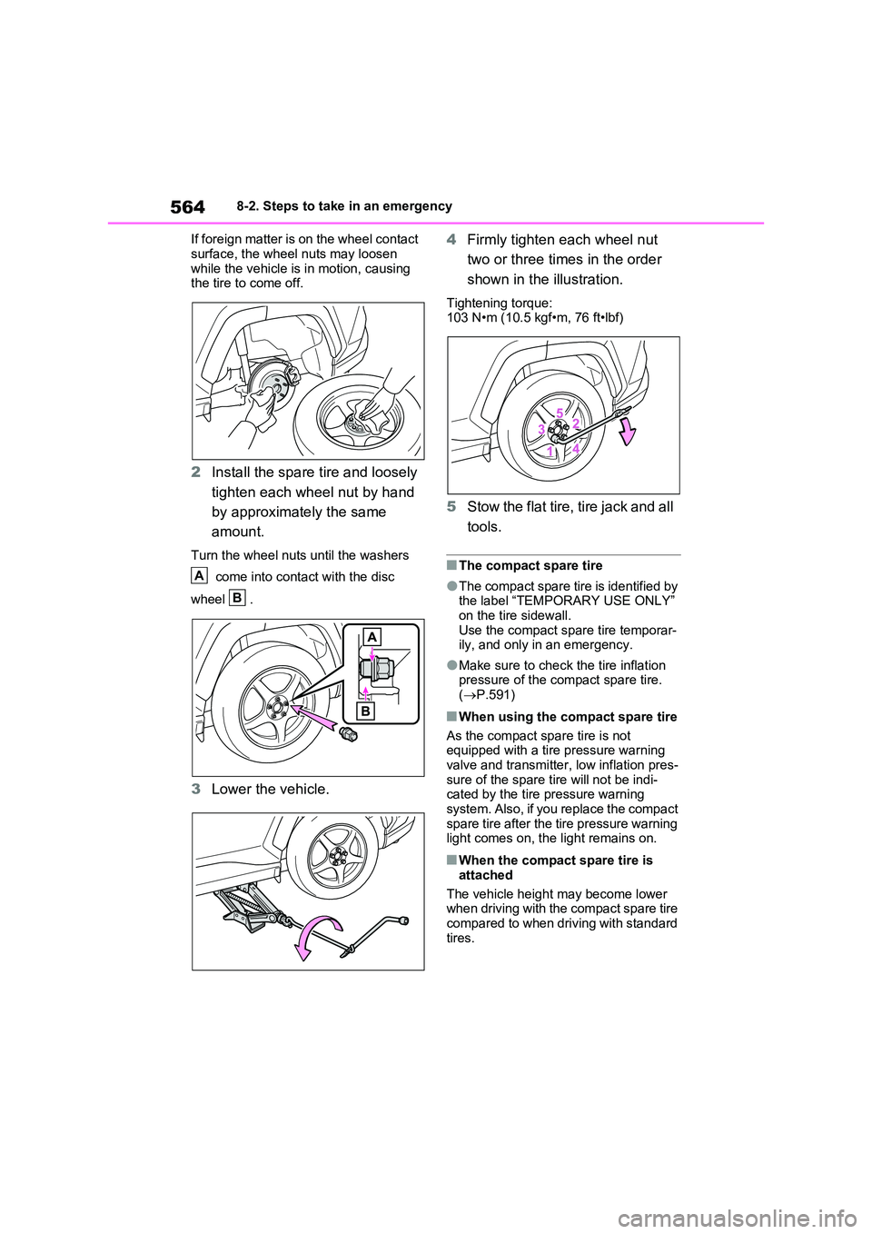
If foreign matter is on the wheel contact
surface, the wheel nuts may loosen while the vehicle is in motion, causing the tire to come off.
2 Install the spare tire and loosely
tighten each wheel nut by hand
by approximately the same
amount.
Turn the wheel nuts until the washers
come into contact with the disc
wheel .
3 Lower the vehicle.
4 Firmly tighten each wheel nut
two or three times in the order
shown in the illustration.
Tightening torque: 103 N•m (10.5 kgf•m, 76 ft•lbf)
5 Stow the flat tire, tire jack and all
tools.
■The compact spare tire
●The compact spare tire is identified by the label “TEMPORARY USE ONLY”
on the tire sidewall. Use the compact spare tire temporar-ily, and only in an emergency.
●Make sure to check the tire inflation pressure of the compact spare tire.
( P.591)
■When using the compact spare tire
As the compact spare tire is not equipped with a tire pressure warning
valve and transmitter, low inflation pres- sure of the spare tire will not be indi-cated by the tire pressure warning
system. Also, if you replace the compact spare tire after the tire pressure warning light comes on, the light remains on.
■When the compact spare tire is
attached
The vehicle height may become lower when driving with the compact spare tire
compared to when driving with standard tires.
A
B
Page 588 of 718
5869-1. Specifications
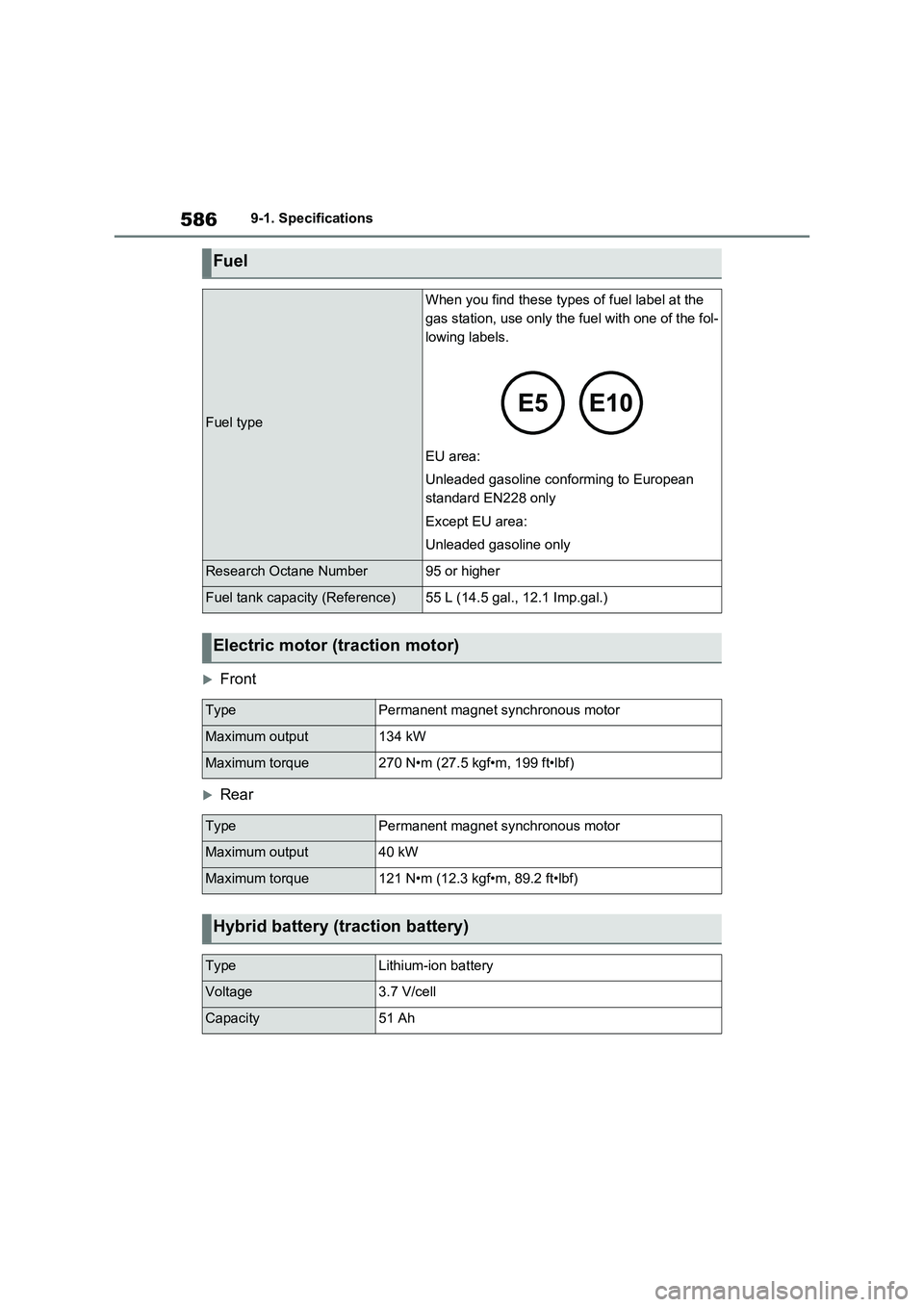
Front
Rear
Fuel
Fuel type
When you find these types of fuel label at the
gas station, use only the fuel with one of the fol-
lowing labels.
EU area:
Unleaded gasoline conforming to European
standard EN228 only
Except EU area:
Unleaded gasoline only
Research Octane Number95 or higher
Fuel tank capacity (Reference)55 L (14.5 gal., 12.1 Imp.gal.)
Electric motor (traction motor)
TypePermanent magnet synchronous motor
Maximum output134 kW
Maximum torque270 N•m (27.5 kgf•m, 199 ft•lbf)
TypePermanent magnet synchronous motor
Maximum output40 kW
Maximum torque121 N•m (12.3 kgf•m, 89.2 ft•lbf)
Hybrid battery (traction battery)
TypeLithium-ion battery
Voltage3.7 V/cell
Capacity51 Ah