check oil TOYOTA SIENNA 2007 Service Repair Manual
[x] Cancel search | Manufacturer: TOYOTA, Model Year: 2007, Model line: SIENNA, Model: TOYOTA SIENNA 2007Pages: 3000, PDF Size: 52.26 MB
Page 1130 of 3000
FU–182GR-FE FUEL – FUEL INJECTOR
FU
INSTALLATION
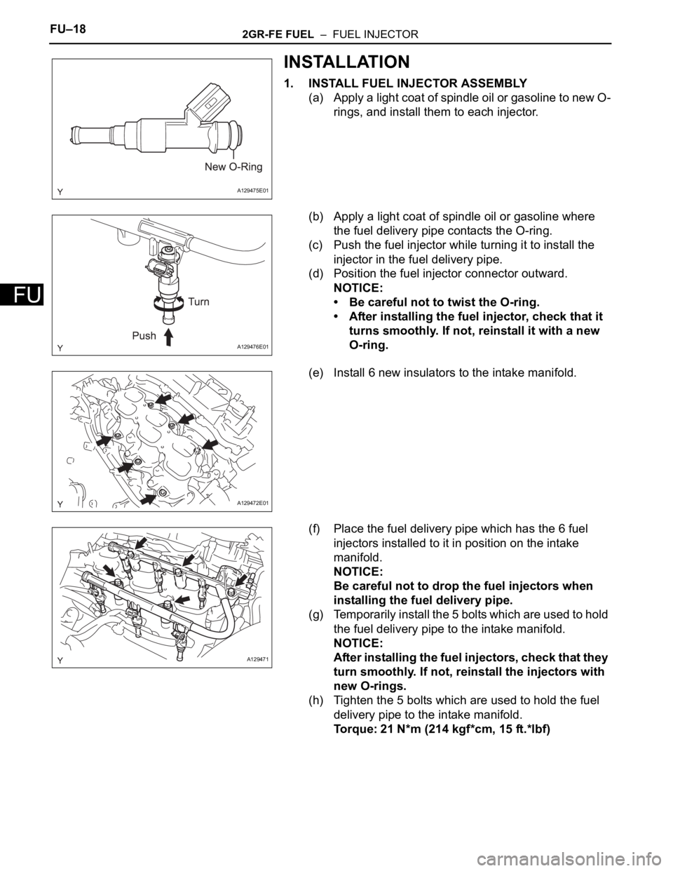
1. INSTALL FUEL INJECTOR ASSEMBLY
(a) Apply a light coat of spindle oil or gasoline to new O-
rings, and install them to each injector.
(b) Apply a light coat of spindle oil or gasoline where
the fuel delivery pipe contacts the O-ring.
(c) Push the fuel injector while turning it to install the
injector in the fuel delivery pipe.
(d) Position the fuel injector connector outward.
NOTICE:
• Be careful not to twist the O-ring.
• After installing the fuel injector, check that it
turns smoothly. If not, reinstall it with a new
O-ring.
(e) Install 6 new insulators to the intake manifold.
(f) Place the fuel delivery pipe which has the 6 fuel
injectors installed to it in position on the intake
manifold.
NOTICE:
Be careful not to drop the fuel injectors when
installing the fuel delivery pipe.
(g) Temporarily install the 5 bolts which are used to hold
the fuel delivery pipe to the intake manifold.
NOTICE:
After installing the fuel injectors, check that they
turn smoothly. If not, reinstall the injectors with
new O-rings.
(h) Tighten the 5 bolts which are used to hold the fuel
delivery pipe to the intake manifold.
Torque: 21 N*m (214 kgf*cm, 15 ft.*lbf)
A129475E01
A129476E01
A129472E01
A129471
Page 1131 of 3000
2GR-FE FUEL – FUEL INJECTORFU–19
FU
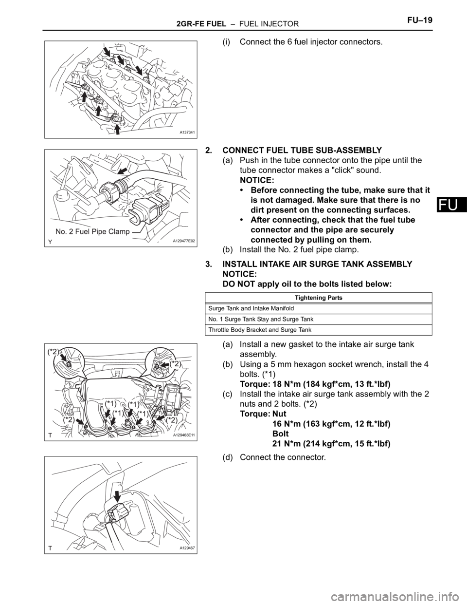
(i) Connect the 6 fuel injector connectors.
2. CONNECT FUEL TUBE SUB-ASSEMBLY
(a) Push in the tube connector onto the pipe until the
tube connector makes a "click" sound.
NOTICE:
• Before connecting the tube, make sure that it
is not damaged. Make sure that there is no
dirt present on the connecting surfaces.
• After connecting, check that the fuel tube
connector and the pipe are securely
connected by pulling on them.
(b) Install the No. 2 fuel pipe clamp.
3. INSTALL INTAKE AIR SURGE TANK ASSEMBLY
NOTICE:
DO NOT apply oil to the bolts listed below:
(a) Install a new gasket to the intake air surge tank
assembly.
(b) Using a 5 mm hexagon socket wrench, install the 4
bolts. (*1)
Torque: 18 N*m (184 kgf*cm, 13 ft.*lbf)
(c) Install the intake air surge tank assembly with the 2
nuts and 2 bolts. (*2)
Torque: Nut
16 N*m (163 kgf*cm, 12 ft.*lbf)
Bolt
21 N*m (214 kgf*cm, 15 ft.*lbf)
(d) Connect the connector.
A137341
A129477E02
Tightening Parts
Surge Tank and Intake Manifold
No. 1 Surge Tank Stay and Surge Tank
Throttle Body Bracket and Surge Tank
A129468E11
A129467
Page 1139 of 3000
FU–182GR-FE FUEL – FUEL INJECTOR
FU
INSTALLATION
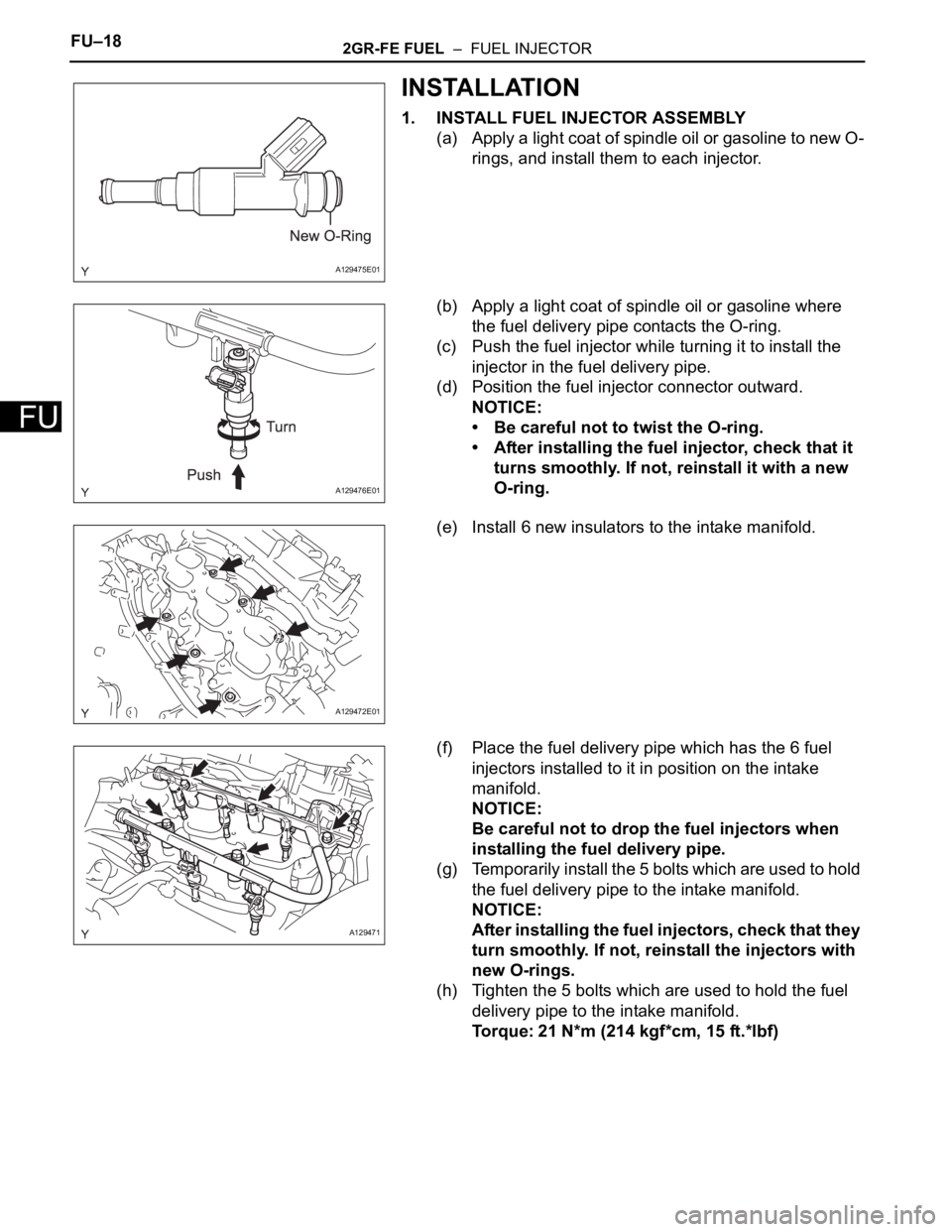
1. INSTALL FUEL INJECTOR ASSEMBLY
(a) Apply a light coat of spindle oil or gasoline to new O-
rings, and install them to each injector.
(b) Apply a light coat of spindle oil or gasoline where
the fuel delivery pipe contacts the O-ring.
(c) Push the fuel injector while turning it to install the
injector in the fuel delivery pipe.
(d) Position the fuel injector connector outward.
NOTICE:
• Be careful not to twist the O-ring.
• After installing the fuel injector, check that it
turns smoothly. If not, reinstall it with a new
O-ring.
(e) Install 6 new insulators to the intake manifold.
(f) Place the fuel delivery pipe which has the 6 fuel
injectors installed to it in position on the intake
manifold.
NOTICE:
Be careful not to drop the fuel injectors when
installing the fuel delivery pipe.
(g) Temporarily install the 5 bolts which are used to hold
the fuel delivery pipe to the intake manifold.
NOTICE:
After installing the fuel injectors, check that they
turn smoothly. If not, reinstall the injectors with
new O-rings.
(h) Tighten the 5 bolts which are used to hold the fuel
delivery pipe to the intake manifold.
Torque: 21 N*m (214 kgf*cm, 15 ft.*lbf)
A129475E01
A129476E01
A129472E01
A129471
Page 1140 of 3000
2GR-FE FUEL – FUEL INJECTORFU–19
FU
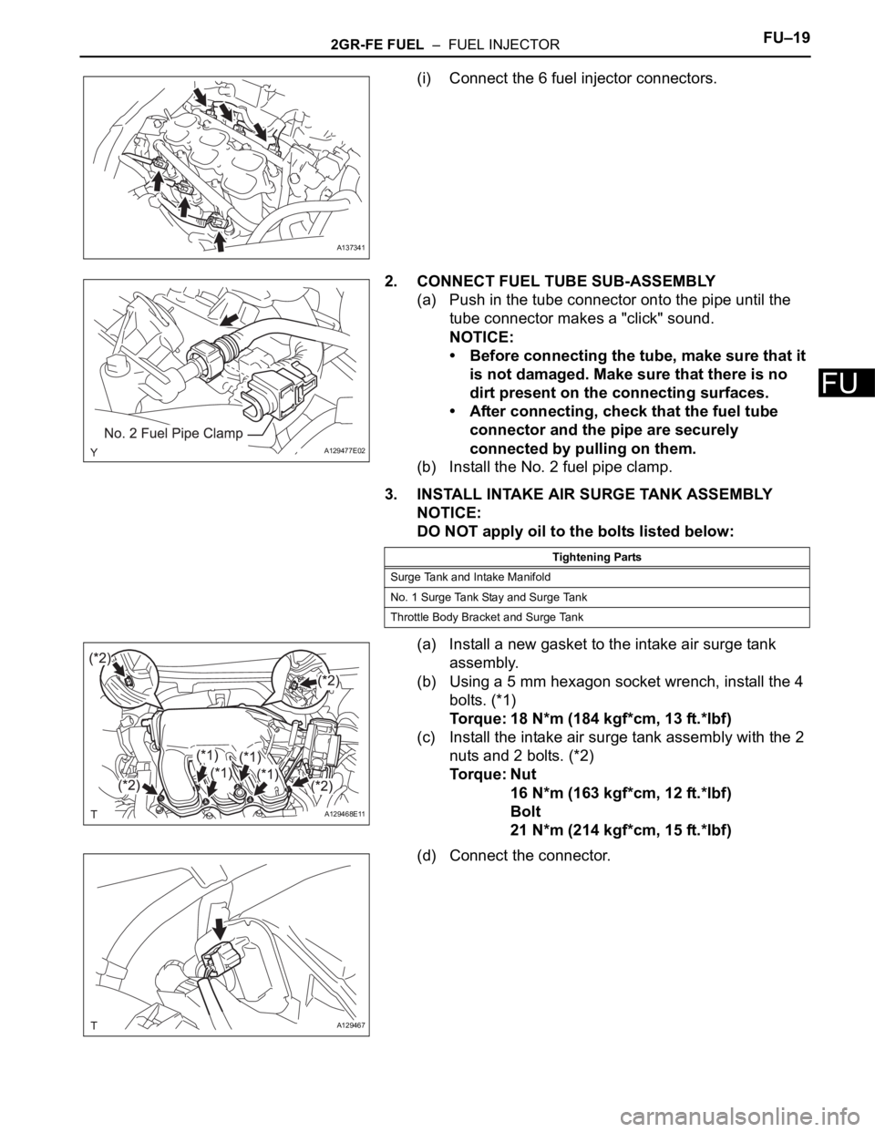
(i) Connect the 6 fuel injector connectors.
2. CONNECT FUEL TUBE SUB-ASSEMBLY
(a) Push in the tube connector onto the pipe until the
tube connector makes a "click" sound.
NOTICE:
• Before connecting the tube, make sure that it
is not damaged. Make sure that there is no
dirt present on the connecting surfaces.
• After connecting, check that the fuel tube
connector and the pipe are securely
connected by pulling on them.
(b) Install the No. 2 fuel pipe clamp.
3. INSTALL INTAKE AIR SURGE TANK ASSEMBLY
NOTICE:
DO NOT apply oil to the bolts listed below:
(a) Install a new gasket to the intake air surge tank
assembly.
(b) Using a 5 mm hexagon socket wrench, install the 4
bolts. (*1)
Torque: 18 N*m (184 kgf*cm, 13 ft.*lbf)
(c) Install the intake air surge tank assembly with the 2
nuts and 2 bolts. (*2)
Torque: Nut
16 N*m (163 kgf*cm, 12 ft.*lbf)
Bolt
21 N*m (214 kgf*cm, 15 ft.*lbf)
(d) Connect the connector.
A137341
A129477E02
Tightening Parts
Surge Tank and Intake Manifold
No. 1 Surge Tank Stay and Surge Tank
Throttle Body Bracket and Surge Tank
A129468E11
A129467
Page 1151 of 3000
2GR-FE FUEL – FUEL PUMPFU–33
FU
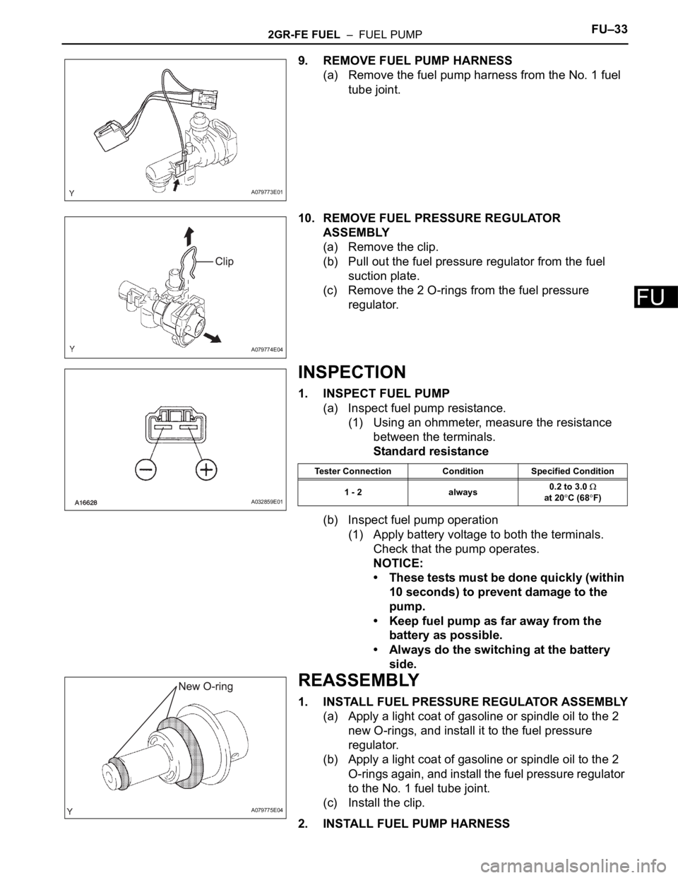
9. REMOVE FUEL PUMP HARNESS
(a) Remove the fuel pump harness from the No. 1 fuel
tube joint.
10. REMOVE FUEL PRESSURE REGULATOR
ASSEMBLY
(a) Remove the clip.
(b) Pull out the fuel pressure regulator from the fuel
suction plate.
(c) Remove the 2 O-rings from the fuel pressure
regulator.
INSPECTION
1. INSPECT FUEL PUMP
(a) Inspect fuel pump resistance.
(1) Using an ohmmeter, measure the resistance
between the terminals.
Standard resistance
(b) Inspect fuel pump operation
(1) Apply battery voltage to both the terminals.
Check that the pump operates.
NOTICE:
• These tests must be done quickly (within
10 seconds) to prevent damage to the
pump.
• Keep fuel pump as far away from the
battery as possible.
• Always do the switching at the battery
side.
REASSEMBLY
1. INSTALL FUEL PRESSURE REGULATOR ASSEMBLY
(a) Apply a light coat of gasoline or spindle oil to the 2
new O-rings, and install it to the fuel pressure
regulator.
(b) Apply a light coat of gasoline or spindle oil to the 2
O-rings again, and install the fuel pressure regulator
to the No. 1 fuel tube joint.
(c) Install the clip.
2. INSTALL FUEL PUMP HARNESS
A079773E01
A079774E04
A032859E01
Tester Connection Condition Specified Condition
1 - 2 always0.2 to 3.0
at 20
C (68F)
A079775E04
Page 1156 of 3000
2GR-FE FUEL – FUEL PUMPFU–33
FU
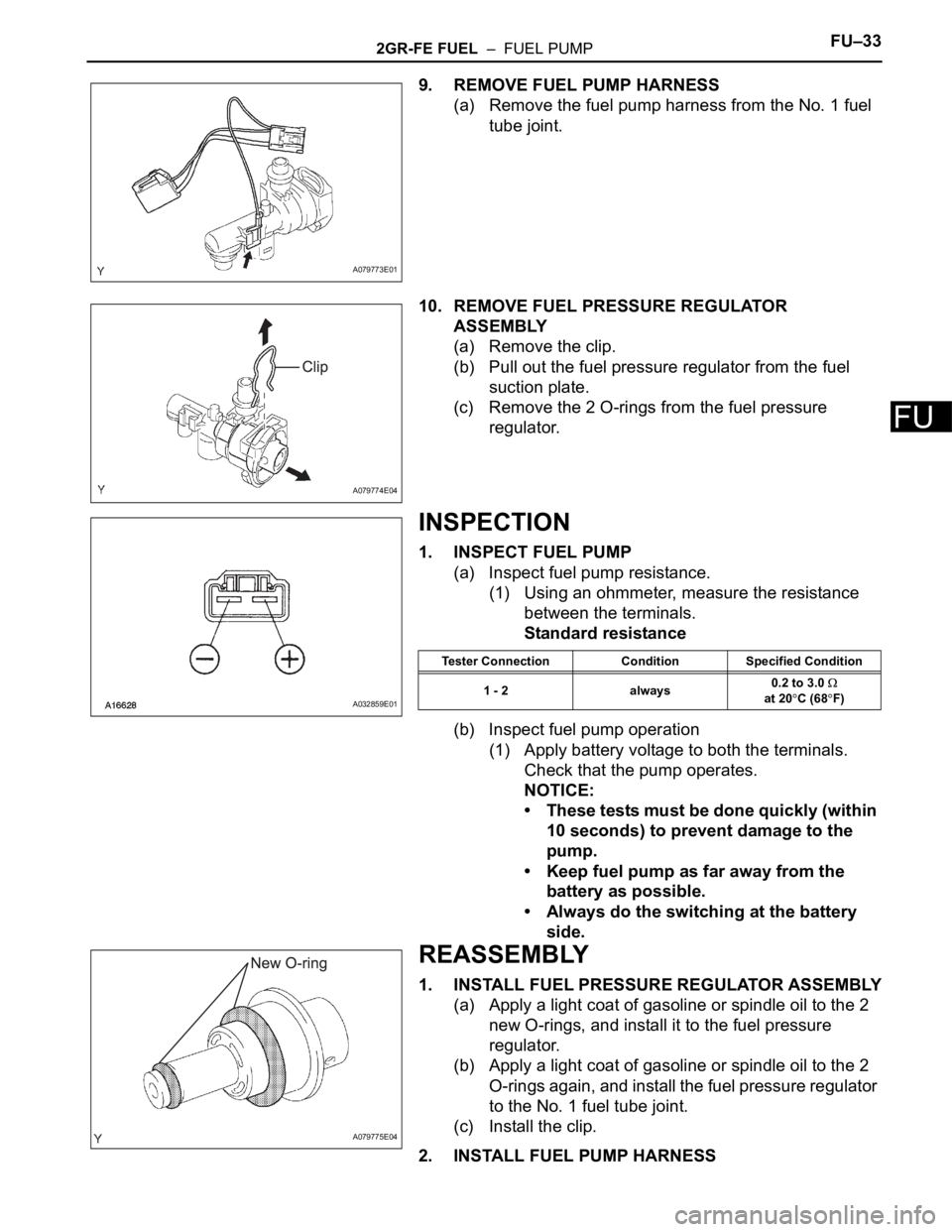
9. REMOVE FUEL PUMP HARNESS
(a) Remove the fuel pump harness from the No. 1 fuel
tube joint.
10. REMOVE FUEL PRESSURE REGULATOR
ASSEMBLY
(a) Remove the clip.
(b) Pull out the fuel pressure regulator from the fuel
suction plate.
(c) Remove the 2 O-rings from the fuel pressure
regulator.
INSPECTION
1. INSPECT FUEL PUMP
(a) Inspect fuel pump resistance.
(1) Using an ohmmeter, measure the resistance
between the terminals.
Standard resistance
(b) Inspect fuel pump operation
(1) Apply battery voltage to both the terminals.
Check that the pump operates.
NOTICE:
• These tests must be done quickly (within
10 seconds) to prevent damage to the
pump.
• Keep fuel pump as far away from the
battery as possible.
• Always do the switching at the battery
side.
REASSEMBLY
1. INSTALL FUEL PRESSURE REGULATOR ASSEMBLY
(a) Apply a light coat of gasoline or spindle oil to the 2
new O-rings, and install it to the fuel pressure
regulator.
(b) Apply a light coat of gasoline or spindle oil to the 2
O-rings again, and install the fuel pressure regulator
to the No. 1 fuel tube joint.
(c) Install the clip.
2. INSTALL FUEL PUMP HARNESS
A079773E01
A079774E04
A032859E01
Tester Connection Condition Specified Condition
1 - 2 always0.2 to 3.0
at 20
C (68F)
A079775E04
Page 1176 of 3000
EC–62GR-FE EMISSION CONTROL – EMISSION CONTROL SYSTEM
EC
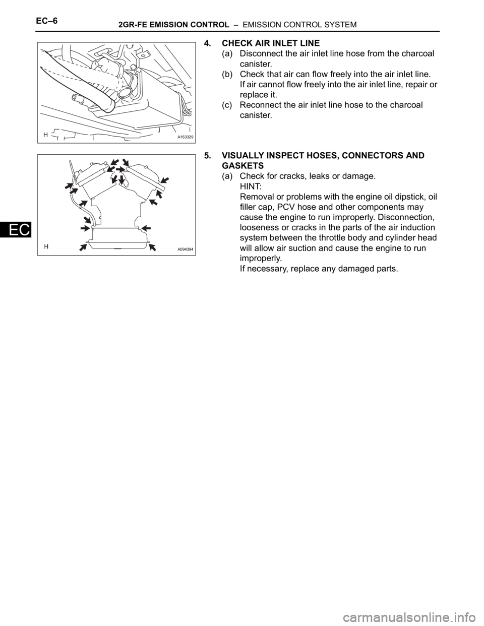
4. CHECK AIR INLET LINE
(a) Disconnect the air inlet line hose from the charcoal
canister.
(b) Check that air can flow freely into the air inlet line.
If air cannot flow freely into the air inlet line, repair or
replace it.
(c) Reconnect the air inlet line hose to the charcoal
canister.
5. VISUALLY INSPECT HOSES, CONNECTORS AND
GASKETS
(a) Check for cracks, leaks or damage.
HINT:
Removal or problems with the engine oil dipstick, oil
filler cap, PCV hose and other components may
cause the engine to run improperly. Disconnection,
looseness or cracks in the parts of the air induction
system between the throttle body and cylinder head
will allow air suction and cause the engine to run
improperly.
If necessary, replace any damaged parts.
A163329
A094394
Page 1238 of 3000
2GR-FE COOLING – COOLING SYSTEMCO–1
CO
COOLING SYSTEM
ON-VEHICLE INSPECTION
1. INSPECT FOR COOLANT LEAK
CAUTION:
Do not remove the radiator cap while the engine and
radiator are still hot. Pressurized, hot engine coolant
and steam may be released and cause serious
burns.
NOTICE:
Before performing each inspection, turn the A/C
switch OFF.
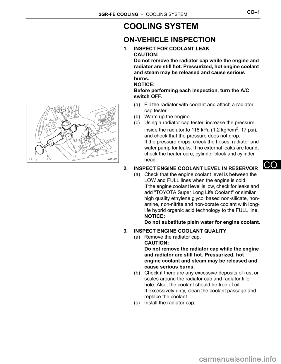
(a) Fill the radiator with coolant and attach a radiator
cap tester.
(b) Warm up the engine.
(c) Using a radiator cap tester, increase the pressure
inside the radiator to 118 kPa (1.2 kgf/cm
2, 17 psi),
and check that the pressure does not drop.
If the pressure drops, check the hoses, radiator and
water pump for leaks. If no external leaks are found,
check the heater core, cylinder block and cylinder
head.
2. INSPECT ENGINE COOLANT LEVEL IN RESERVOIR
(a) Check that the engine coolant level is between the
LOW and FULL lines when the engine is cold.
If the engine coolant level is low, check for leaks and
add "TOYOTA Super Long Life Coolant" or similar
high quality ethylene glycol based non-silicate, non-
amine, non-nitrite and non-borate coolant with long-
life hybrid organic acid technology to the FULL line.
NOTICE:
Do not substitute plain water for engine coolant.
3. INSPECT ENGINE COOLANT QUALITY
(a) Remove the radiator cap.
CAUTION:
Do not remove the radiator cap while the engine
and radiator are still hot. Pressurized, hot
engine coolant and steam may be released and
cause serious burns.
(b) Check if there are any excessive deposits of rust or
scales around the radiator cap and radiator filler
hole. Also, the coolant should be free of oil.
If excessively dirty, clean the coolant passage and
replace the coolant.
(c) Install the radiator cap.
A161453
Page 1292 of 3000
2GR-FE LUBRICATION – OIL PUMPLU–13
LU
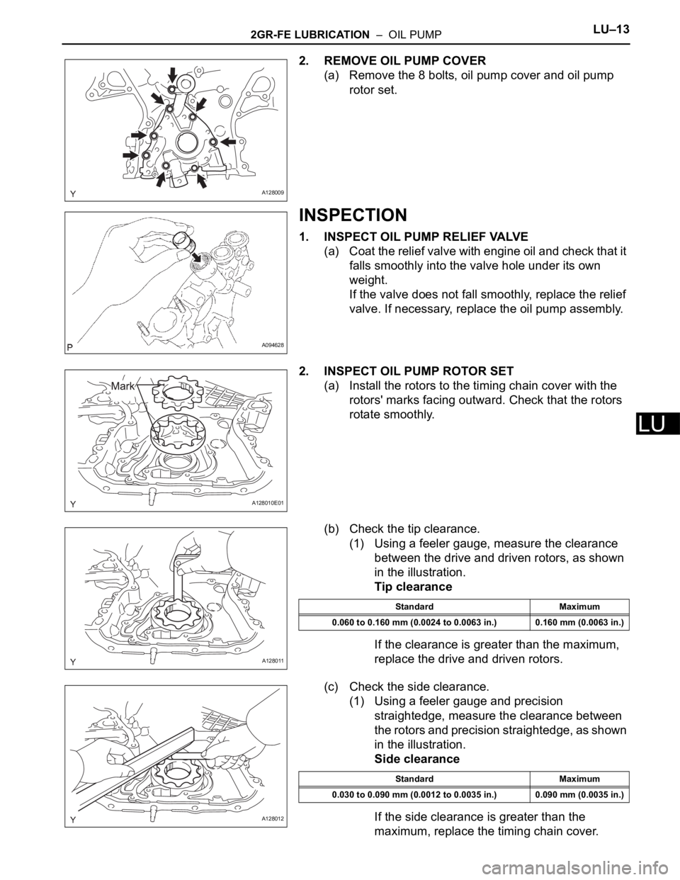
2. REMOVE OIL PUMP COVER
(a) Remove the 8 bolts, oil pump cover and oil pump
rotor set.
INSPECTION
1. INSPECT OIL PUMP RELIEF VALVE
(a) Coat the relief valve with engine oil and check that it
falls smoothly into the valve hole under its own
weight.
If the valve does not fall smoothly, replace the relief
valve. If necessary, replace the oil pump assembly.
2. INSPECT OIL PUMP ROTOR SET
(a) Install the rotors to the timing chain cover with the
rotors' marks facing outward. Check that the rotors
rotate smoothly.
(b) Check the tip clearance.
(1) Using a feeler gauge, measure the clearance
between the drive and driven rotors, as shown
in the illustration.
Tip clearance
If the clearance is greater than the maximum,
replace the drive and driven rotors.
(c) Check the side clearance.
(1) Using a feeler gauge and precision
straightedge, measure the clearance between
the rotors and precision straightedge, as shown
in the illustration.
Side clearance
If the side clearance is greater than the
maximum, replace the timing chain cover.
A128009
A094628
A128010E01
A128011
Standard Maximum
0.060 to 0.160 mm (0.0024 to 0.0063 in.) 0.160 mm (0.0063 in.)
A128012
Standard Maximum
0.030 to 0.090 mm (0.0012 to 0.0035 in.) 0.090 mm (0.0035 in.)
Page 1293 of 3000
LU–142GR-FE LUBRICATION – OIL PUMP
LU
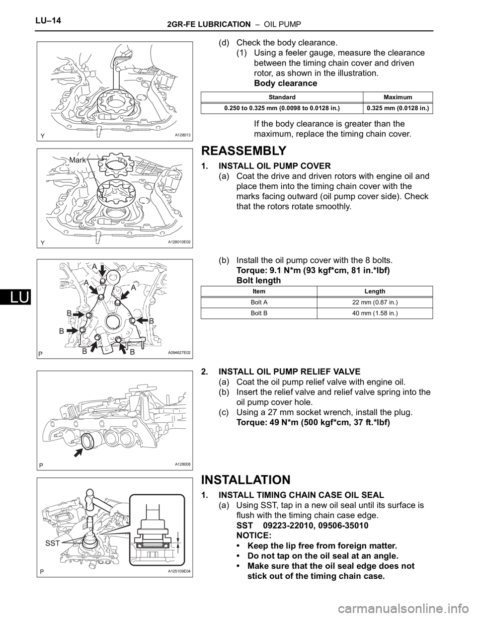
(d) Check the body clearance.
(1) Using a feeler gauge, measure the clearance
between the timing chain cover and driven
rotor, as shown in the illustration.
Body clearance
If the body clearance is greater than the
maximum, replace the timing chain cover.
REASSEMBLY
1. INSTALL OIL PUMP COVER
(a) Coat the drive and driven rotors with engine oil and
place them into the timing chain cover with the
marks facing outward (oil pump cover side). Check
that the rotors rotate smoothly.
(b) Install the oil pump cover with the 8 bolts.
Torque: 9.1 N*m (93 kgf*cm, 81 in.*lbf)
Bolt length
2. INSTALL OIL PUMP RELIEF VALVE
(a) Coat the oil pump relief valve with engine oil.
(b) Insert the relief valve and relief valve spring into the
oil pump cover hole.
(c) Using a 27 mm socket wrench, install the plug.
Torque: 49 N*m (500 kgf*cm, 37 ft.*lbf)
INSTALLATION
1. INSTALL TIMING CHAIN CASE OIL SEAL
(a) Using SST, tap in a new oil seal until its surface is
flush with the timing chain case edge.
SST 09223-22010, 09506-35010
NOTICE:
• Keep the lip free from foreign matter.
• Do not tap on the oil seal at an angle.
• Make sure that the oil seal edge does not
stick out of the timing chain case.
A128013
Standard Maximum
0.250 to 0.325 mm (0.0098 to 0.0128 in.) 0.325 mm (0.0128 in.)
A128010E02
A094627E02
Item Length
Bolt A 22 mm (0.87 in.)
Bolt B 40 mm (1.58 in.)
A128008
A125109E04