check oil TOYOTA SIENNA 2007 Service Repair Manual
[x] Cancel search | Manufacturer: TOYOTA, Model Year: 2007, Model line: SIENNA, Model: TOYOTA SIENNA 2007Pages: 3000, PDF Size: 52.26 MB
Page 1555 of 3000
AX–160U151E AUTOMATIC TRANSAXLE – DIFFERENTIAL OIL SEAL
AX
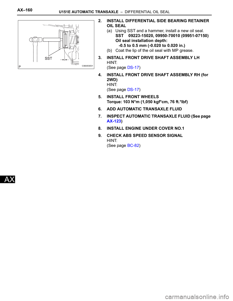
2. INSTALL DIFFERENTIAL SIDE BEARING RETAINER
OIL SEAL
(a) Using SST and a hammer, install a new oil seal.
SST 09223-15020, 09950-70010 (09951-07150)
Oil seal installation depth:
-0.5 to 0.5 mm (-0.020 to 0.020 in.)
(b) Coat the lip of the oil seal with MP grease.
3. INSTALL FRONT DRIVE SHAFT ASSEMBLY LH
HINT:
(See page DS-17)
4. INSTALL FRONT DRIVE SHAFT ASSEMBLY RH (for
2WD)
HINT:
(See page DS-17)
5. INSTALL FRONT WHEELS
Torque: 103 N*m (1,050 kgf*cm, 76 ft.*lbf)
6. ADD AUTOMATIC TRANSAXLE FLUID
7. INSPECT AUTOMATIC TRANSAXLE FLUID (See page
AX-123)
8. INSTALL ENGINE UNDER COVER NO.1
9. CHECK ABS SPEED SENSOR SIGNAL
HINT:
(See page BC-82)
C083053E01
Page 1576 of 3000
U151E AUTOMATIC TRANSAXLE – AUTOMATIC TRANSAXLE UNITAX–197
AX
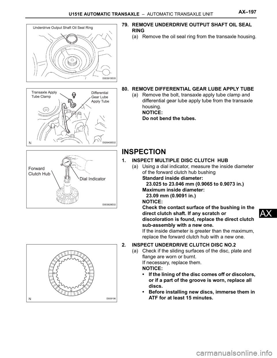
79. REMOVE UNDERDRIVE OUTPUT SHAFT OIL SEAL
RING
(a) Remove the oil seal ring from the transaxle housing.
80. REMOVE DIFFERENTIAL GEAR LUBE APPLY TUBE
(a) Remove the bolt, transaxle apply tube clamp and
differential gear lube apply tube from the transaxle
housing.
NOTICE:
Do not bend the tubes.
INSPECTION
1. INSPECT MULTIPLE DISC CLUTCH HUB
(a) Using a dial indicator, measure the inside diameter
of the forward clutch hub bushing
Standard inside diameter:
23.025 to 23.046 mm (0.9065 to 0.9073 in.)
Maximum inside diameter:
23.09 mm (0.9091 in.)
NOTICE:
Check the contact surface of the bushing in the
direct clutch shaft. If any scratch or
discoloration is found, replace the direct clutch
sub-assembly with a new one.
If the inside diameter is greater than the maximum,
replace the forward clutch hub with a new one.
2. INSPECT UNDERDRIVE CLUTCH DISC NO.2
(a) Check if the sliding surfaces of the disc, plate and
flange are worn or burnt.
If necessary, replace them.
NOTICE:
• If the lining of the disc comes off or discolors,
or if a part of the groove is worn, replace all
discs.
• Before installing new discs, immerse them in
ATF for at least 15 minutes.
D003915E05
D026400E02
D003829E02
D009196
Page 1614 of 3000
AX–228U151E AUTOMATIC TRANSAXLE – AUTOMATIC TRANSAXLE UNIT
AX
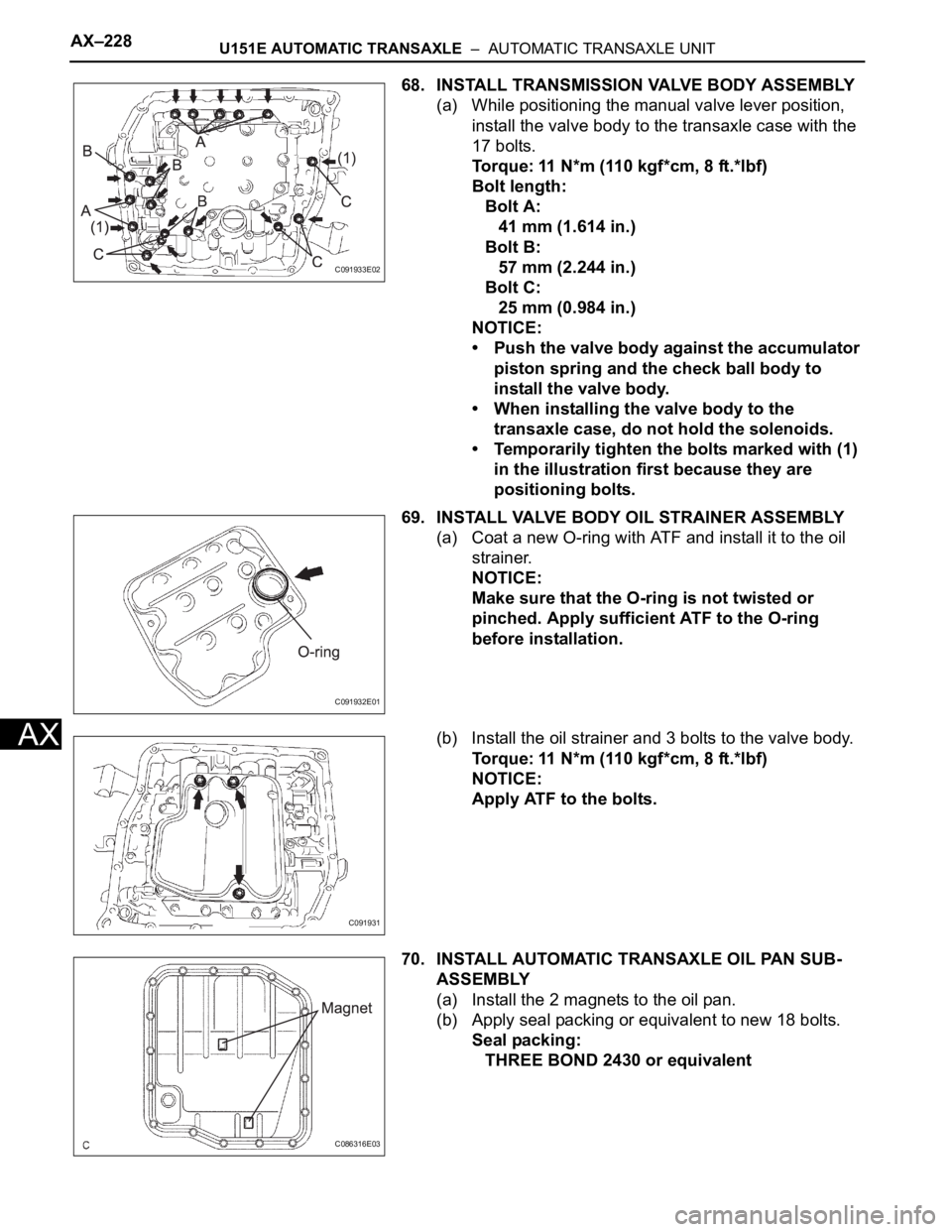
68. INSTALL TRANSMISSION VALVE BODY ASSEMBLY
(a) While positioning the manual valve lever position,
install the valve body to the transaxle case with the
17 bolts.
Torque: 11 N*m (110 kgf*cm, 8 ft.*lbf)
Bolt length:
Bolt A:
41 mm (1.614 in.)
Bolt B:
57 mm (2.244 in.)
Bolt C:
25 mm (0.984 in.)
NOTICE:
• Push the valve body against the accumulator
piston spring and the check ball body to
install the valve body.
• When installing the valve body to the
transaxle case, do not hold the solenoids.
• Temporarily tighten the bolts marked with (1)
in the illustration first because they are
positioning bolts.
69. INSTALL VALVE BODY OIL STRAINER ASSEMBLY
(a) Coat a new O-ring with ATF and install it to the oil
strainer.
NOTICE:
Make sure that the O-ring is not twisted or
pinched. Apply sufficient ATF to the O-ring
before installation.
(b) Install the oil strainer and 3 bolts to the valve body.
Torque: 11 N*m (110 kgf*cm, 8 ft.*lbf)
NOTICE:
Apply ATF to the bolts.
70. INSTALL AUTOMATIC TRANSAXLE OIL PAN SUB-
ASSEMBLY
(a) Install the 2 magnets to the oil pan.
(b) Apply seal packing or equivalent to new 18 bolts.
Seal packing:
THREE BOND 2430 or equivalent
C091933E02
C091932E01
C091931
C086316E03
Page 1619 of 3000
U151E AUTOMATIC TRANSAXLE – TORQUE CONVERTER CLUTCH AND DRIVE PLATEAX–171
AX
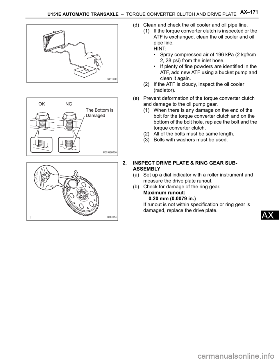
(d) Clean and check the oil cooler and oil pipe line.
(1) If the torque converter clutch is inspected or the
ATF is exchanged, clean the oil cooler and oil
pipe line.
HINT:
• Spray compressed air of 196 kPa (2 kgf/cm
2, 28 psi) from the inlet hose.
• If plenty of fine powders are identified in the
ATF, add new ATF using a bucket pump and
clean it again.
(2) If the ATF is cloudy, inspect the oil cooler
(radiator).
(e) Prevent deformation of the torque converter clutch
and damage to the oil pump gear.
(1) When there is any damage on the end of the
bolt for the torque converter clutch and on the
bottom of the bolt hole, replace the bolt and the
torque converter clutch.
(2) All of the bolts must be same length.
(3) Bolts with washers must be used.
2. INSPECT DRIVE PLATE & RING GEAR SUB-
ASSEMBLY
(a) Set up a dial indicator with a roller instrument and
measure the drive plate runout.
(b) Check for damage of the ring gear.
Maximum runout:
0.20 mm (0.0079 in.)
If runout is not within specification or ring gear is
damaged, replace the drive plate.
C011090
D025368E08
C081014
Page 1641 of 3000
U151E AUTOMATIC TRANSAXLE – AUTOMATIC TRANSAXLE UNITAX–197
AX
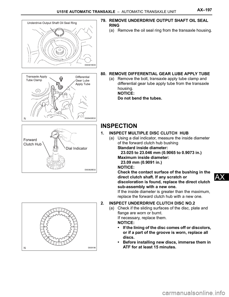
79. REMOVE UNDERDRIVE OUTPUT SHAFT OIL SEAL
RING
(a) Remove the oil seal ring from the transaxle housing.
80. REMOVE DIFFERENTIAL GEAR LUBE APPLY TUBE
(a) Remove the bolt, transaxle apply tube clamp and
differential gear lube apply tube from the transaxle
housing.
NOTICE:
Do not bend the tubes.
INSPECTION
1. INSPECT MULTIPLE DISC CLUTCH HUB
(a) Using a dial indicator, measure the inside diameter
of the forward clutch hub bushing
Standard inside diameter:
23.025 to 23.046 mm (0.9065 to 0.9073 in.)
Maximum inside diameter:
23.09 mm (0.9091 in.)
NOTICE:
Check the contact surface of the bushing in the
direct clutch shaft. If any scratch or
discoloration is found, replace the direct clutch
sub-assembly with a new one.
If the inside diameter is greater than the maximum,
replace the forward clutch hub with a new one.
2. INSPECT UNDERDRIVE CLUTCH DISC NO.2
(a) Check if the sliding surfaces of the disc, plate and
flange are worn or burnt.
If necessary, replace them.
NOTICE:
• If the lining of the disc comes off or discolors,
or if a part of the groove is worn, replace all
discs.
• Before installing new discs, immerse them in
ATF for at least 15 minutes.
D003915E05
D026400E02
D003829E02
D009196
Page 1652 of 3000
AX–244U151E AUTOMATIC TRANSAXLE – FORWARD CLUTCH
AX
REASSEMBLY
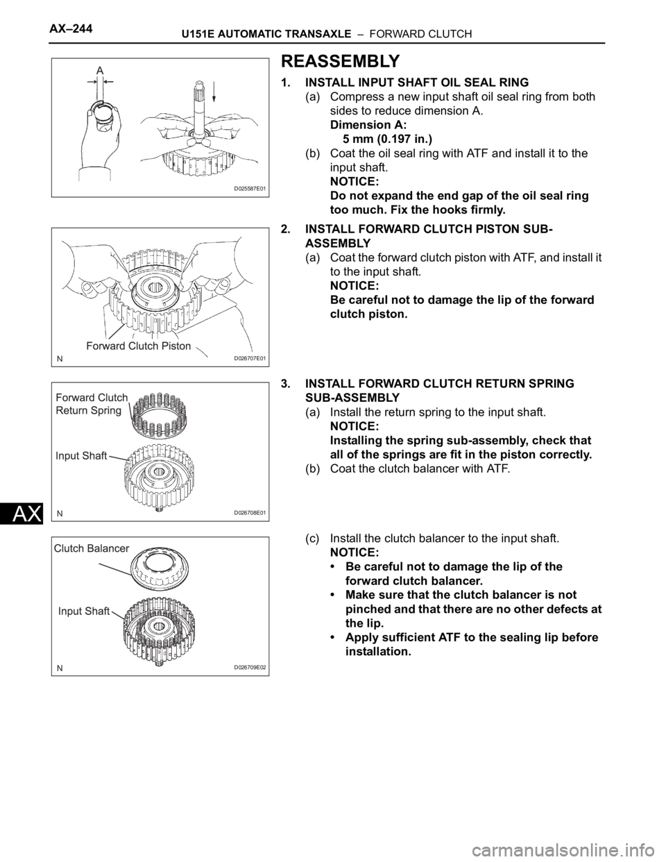
1. INSTALL INPUT SHAFT OIL SEAL RING
(a) Compress a new input shaft oil seal ring from both
sides to reduce dimension A.
Dimension A:
5 mm (0.197 in.)
(b) Coat the oil seal ring with ATF and install it to the
input shaft.
NOTICE:
Do not expand the end gap of the oil seal ring
too much. Fix the hooks firmly.
2. INSTALL FORWARD CLUTCH PISTON SUB-
ASSEMBLY
(a) Coat the forward clutch piston with ATF, and install it
to the input shaft.
NOTICE:
Be careful not to damage the lip of the forward
clutch piston.
3. INSTALL FORWARD CLUTCH RETURN SPRING
SUB-ASSEMBLY
(a) Install the return spring to the input shaft.
NOTICE:
Installing the spring sub-assembly, check that
all of the springs are fit in the piston correctly.
(b) Coat the clutch balancer with ATF.
(c) Install the clutch balancer to the input shaft.
NOTICE:
• Be careful not to damage the lip of the
forward clutch balancer.
• Make sure that the clutch balancer is not
pinched and that there are no other defects at
the lip.
• Apply sufficient ATF to the sealing lip before
installation.
D025587E01
D026707E01
D026708E01
D026709E02
Page 1699 of 3000
AX–16U151F AUTOMATIC TRANSAXLE – AUTOMATIC TRANSAXLE SYSTEM
AX
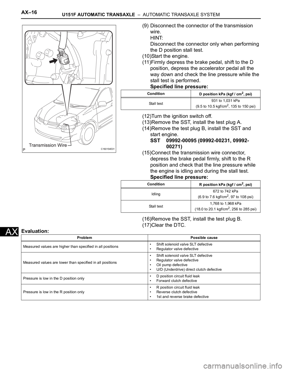
(9) Disconnect the connector of the transmission
wire.
HINT:
Disconnect the connector only when performing
the D position stall test.
(10)Start the engine.
(11)Firmly depress the brake pedal, shift to the D
position, depress the accelerator pedal all the
way down and check the line pressure while the
stall test is performed.
Specified line pressure:
(12)Turn the ignition switch off.
(13)Remove the SST, install the test plug A.
(14)Remove the test plug B, install the SST and
start engine.
SST 09992-00095 (09992-00231, 09992-
00271)
(15)Connect the transmission wire connector,
depress the brake pedal firmly, shift to the R
position and check that the line pressure while
the engine is idling and during the stall test.
Specified line pressure:
(16)Remove the SST, install the test plug B.
(17)Clear the DTC.
Evaluation:
C160154E01
Condition
D position kPa (kgf / cm2, psi)
Stall test931 to 1,031 kPa
(9.5 to 10.5 kgf/cm
2, 135 to 150 psi)
Condition
R position kPa (kgf / cm
2, psi)
Idling672 to 742 kPa
(6.9 to 7.6 kgf/cm
2, 97 to 108 psi)
Stall test1,768 to 1,968 kPa
(18.0 to 20.1 kgf/cm
2, 256 to 285 psi)
Problem Possible cause
Measured values are higher than specified in all positions• Shift solenoid valve SLT defective
• Regulator valve defective
Measured values are lower than specified in all positions• Shift solenoid valve SLT defective
• Regulator valve defective
• Oil pump defective
• U/D (Underdrive) direct clutch defective
Pressure is low in the D position only• D position circuit fluid leak
• Forward clutch defective
Pressure is low in the R position only• R position circuit fluid leak
• Reverse clutch defective
• 1st and reverse brake defective
Page 1729 of 3000
U151F AUTOMATIC TRANSAXLE – AUTOMATIC TRANSAXLE SYSTEMAX–57
AX
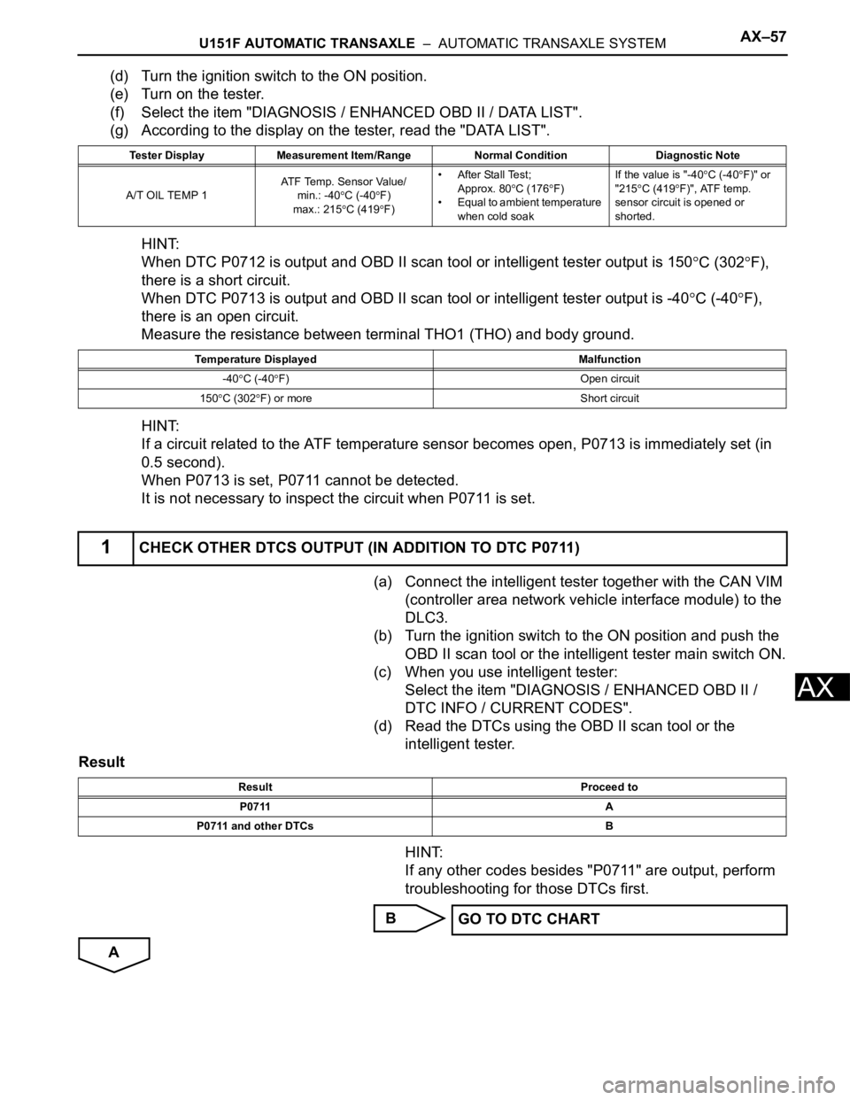
(d) Turn the ignition switch to the ON position.
(e) Turn on the tester.
(f) Select the item "DIAGNOSIS / ENHANCED OBD II / DATA LIST".
(g) According to the display on the tester, read the "DATA LIST".
HINT:
When DTC P0712 is output and OBD II scan tool or intelligent tester output is 150
C (302F),
there is a short circuit.
When DTC P0713 is output and OBD II scan tool or intelligent tester output is -40
C (-40F),
there is an open circuit.
Measure the resistance between terminal THO1 (THO) and body ground.
HINT:
If a circuit related to the ATF temperature sensor becomes open, P0713 is immediately set (in
0.5 second).
When P0713 is set, P0711 cannot be detected.
It is not necessary to inspect the circuit when P0711 is set.
(a) Connect the intelligent tester together with the CAN VIM
(controller area network vehicle interface module) to the
DLC3.
(b) Turn the ignition switch to the ON position and push the
OBD II scan tool or the intelligent tester main switch ON.
(c) When you use intelligent tester:
Select the item "DIAGNOSIS / ENHANCED OBD II /
DTC INFO / CURRENT CODES".
(d) Read the DTCs using the OBD II scan tool or the
intelligent tester.
Result
HINT:
If any other codes besides "P0711" are output, perform
troubleshooting for those DTCs first.
B
A
Tester Display Measurement Item/Range Normal Condition Diagnostic Note
A/T OIL TEMP 1ATF Temp. Sensor Value/
min.: -40
C (-40F)
max.: 215
C (419F)• After Stall Test;
Approx. 80
C (176F)
• Equal to ambient temperature
when cold soakIf the value is "-40
C (-40F)" or
"215
C (419F)", ATF temp.
sensor circuit is opened or
shorted.
Temperature Displayed Malfunction
-40
C (-40F) Open circuit
150
C (302F) or more Short circuit
1CHECK OTHER DTCS OUTPUT (IN ADDITION TO DTC P0711)
Result Proceed to
P0711 A
P0711 and other DTCs B
GO TO DTC CHART
Page 1805 of 3000
U151F AUTOMATIC TRANSAXLE – AUTOMATIC TRANSAXLE FLUIDAX–123
AX
AUTOMATIC TRANSAXLE FLUID
ON-VEHICLE INSPECTION
1. CHECK FLUID LEVEL
HINT:
Drive the vehicle so that the engine and transaxle are at
normal operating temperature.
Fluid temperature:
70 to 80
C (158 to 176F)
(a) Park the vehicle on a level surface and set the
parking brake.
(b) With the engine idling and the brake pedal
depressed, move the shift lever to all positions from
P to L and return to the P position.
(c) Take out the dipstick and wipe it clean.
(d) Put the dipstick back all the way.
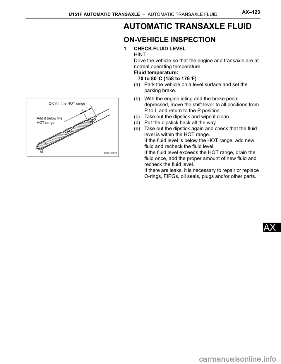
(e) Take out the dipstick again and check that the fluid
level is within the HOT range.
If the fluid level is below the HOT range, add new
fluid and recheck the fluid level.
If the fluid level exceeds the HOT range, drain the
fluid once, add the proper amount of new fluid and
recheck the fluid level.
If there are leaks, it is necessary to repair or replace
O-rings, FIPGs, oil seals, plugs and/or other parts.
D025120E05
Page 1809 of 3000
AX–16U151F AUTOMATIC TRANSAXLE – AUTOMATIC TRANSAXLE SYSTEM
AX
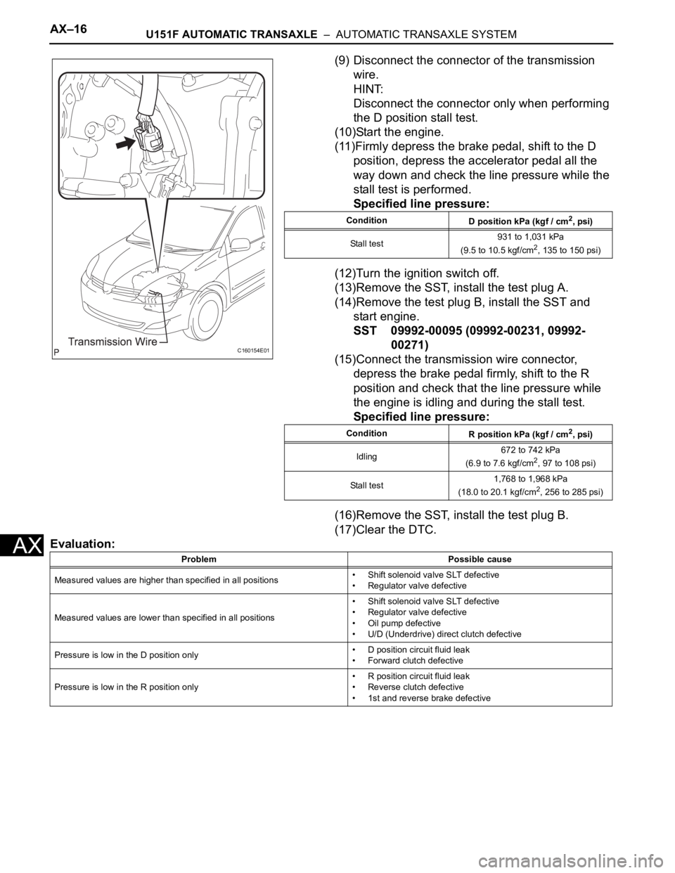
(9) Disconnect the connector of the transmission
wire.
HINT:
Disconnect the connector only when performing
the D position stall test.
(10)Start the engine.
(11)Firmly depress the brake pedal, shift to the D
position, depress the accelerator pedal all the
way down and check the line pressure while the
stall test is performed.
Specified line pressure:
(12)Turn the ignition switch off.
(13)Remove the SST, install the test plug A.
(14)Remove the test plug B, install the SST and
start engine.
SST 09992-00095 (09992-00231, 09992-
00271)
(15)Connect the transmission wire connector,
depress the brake pedal firmly, shift to the R
position and check that the line pressure while
the engine is idling and during the stall test.
Specified line pressure:
(16)Remove the SST, install the test plug B.
(17)Clear the DTC.
Evaluation:
C160154E01
Condition
D position kPa (kgf / cm2, psi)
Stall test931 to 1,031 kPa
(9.5 to 10.5 kgf/cm
2, 135 to 150 psi)
Condition
R position kPa (kgf / cm
2, psi)
Idling672 to 742 kPa
(6.9 to 7.6 kgf/cm
2, 97 to 108 psi)
Stall test1,768 to 1,968 kPa
(18.0 to 20.1 kgf/cm
2, 256 to 285 psi)
Problem Possible cause
Measured values are higher than specified in all positions• Shift solenoid valve SLT defective
• Regulator valve defective
Measured values are lower than specified in all positions• Shift solenoid valve SLT defective
• Regulator valve defective
• Oil pump defective
• U/D (Underdrive) direct clutch defective
Pressure is low in the D position only• D position circuit fluid leak
• Forward clutch defective
Pressure is low in the R position only• R position circuit fluid leak
• Reverse clutch defective
• 1st and reverse brake defective