TOYOTA SIENNA 2007 Service Repair Manual
Manufacturer: TOYOTA, Model Year: 2007, Model line: SIENNA, Model: TOYOTA SIENNA 2007Pages: 3000, PDF Size: 52.26 MB
Page 1531 of 3000
AX–26U151E AUTOMATIC TRANSAXLE – AUTOMATIC TRANSAXLE SYSTEM
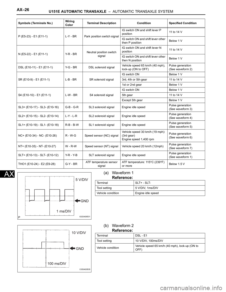
AX(a) Waveform 1
Reference:
(b) Waveform 2
Reference:
P (E5-23) - E1 (E11-1) L-Y - BR Park position switch signalIG switch ON and shift lever P
position11 to 14 V
IG switch ON and shift lever other
then P positionBelow 1 V
N (E5-22) - E1 (E11-1) Y-R - BRNeutral position switch
signalIG switch ON and shift lever N
position11 to 14 V
IG switch ON and shift lever other
then N positionBelow 1 V
DSL (E10-11) - E1 (E11-1) Y-G - BR DSL solenoid signalVehicle speed 65 km/h (40 mph),
lock-up (ON to OFF)Pulse generation
(See waveform 2)
SR (E10-9) - E1 (E11-1) L-B - BR SR solenoid signalIG switch ON Below 1 V
3rd, 4th or 5th gear 11 to 14 V
1st or 2nd gear Below 1 V
S4 (E10-10) - E1 (E11-1) L-W - BR S4 solenoid signalIG switch ON Below 1 V
5th gear 11 to 14 V
Except 5th gear Below 1 V
SL3+ (E10-17) - SL3- (E10-16) G-B - G-R SL3 solenoid signal Engine idle speedPulse generation
(See waveform 3)
SL2+ (E10-15) - SL2- (E10-14) L-Y - L-R SL2 solenoid signal Engine idle speedPulse generation
(See waveform 4)
SL1+ (E10-19) - SL1- (E10-18) R-B - B-W SL1 solenoid signal Engine idle speedPulse generation
(See waveform 5)
NC+ (E10-34) - NC- (E10-26) R - W-G Speed sensor (NC) signalVehicle speed 30 km/h (19 mph):
(3rd gear)
Engine speed 1,400 rpmPulse generation
(See waveform 6)
NT+ (E10-35) - NT- (E10-27) W - R-W Speed sensor (NT) signal Vehicle speed 20 km/h (12mph)Pulse generation
(See waveform 7)
SLT+ (E10-13) - SLT- (E10-12) Y-R - Y-B SLT solenoid signal Engine idle speedPulse generation
(See waveform 1)
THO1 (E10-24) - E2 (E9-28) G-Y - BRATF temperature sensor
signalATF temperature: 115
C (239F)
or moreBelow 1.5 V Symbols (Terminals No.)Wiring
ColorTerminal Description Condition Specified Condition
G023426E01
Terminal SLT+ - SLT-
Tool setting 5 V/DIV, 1ms/DIV
Vehicle condition Engine idle speed
C053420E05
Terminal DSL - E1
Tool setting 10 V/DIV, 100ms/DIV
Vehicle conditionVehicle speed 65 km/h (40 mph), lock-up (ON to
OFF)
Page 1532 of 3000
U151E AUTOMATIC TRANSAXLE – AUTOMATIC TRANSAXLE SYSTEMAX–27
AX
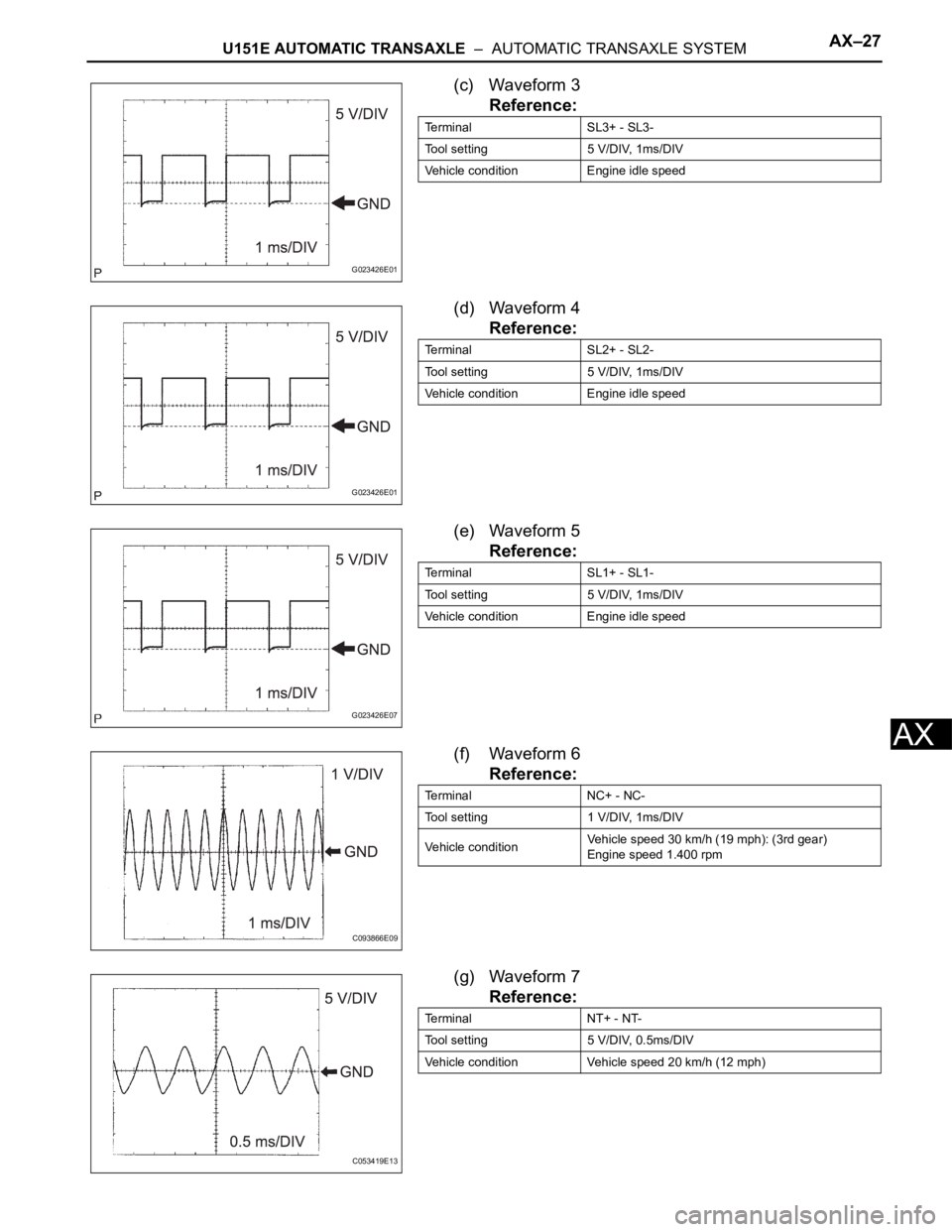
(c) Waveform 3
Reference:
(d) Waveform 4
Reference:
(e) Waveform 5
Reference:
(f) Waveform 6
Reference:
(g) Waveform 7
Reference:
G023426E01
Terminal SL3+ - SL3-
Tool setting 5 V/DIV, 1ms/DIV
Vehicle condition Engine idle speed
G023426E01
Terminal SL2+ - SL2-
Tool setting 5 V/DIV, 1ms/DIV
Vehicle condition Engine idle speed
G023426E07
Terminal SL1+ - SL1-
Tool setting 5 V/DIV, 1ms/DIV
Vehicle condition Engine idle speed
C093866E09
Terminal NC+ - NC-
Tool setting 1 V/DIV, 1ms/DIV
Vehicle conditionVehicle speed 30 km/h (19 mph): (3rd gear)
Engine speed 1.400 rpm
C053419E13
Terminal NT+ - NT-
Tool setting 5 V/DIV, 0.5ms/DIV
Vehicle condition Vehicle speed 20 km/h (12 mph)
Page 1533 of 3000
AX–28U151E AUTOMATIC TRANSAXLE – AUTOMATIC TRANSAXLE SYSTEM
AX
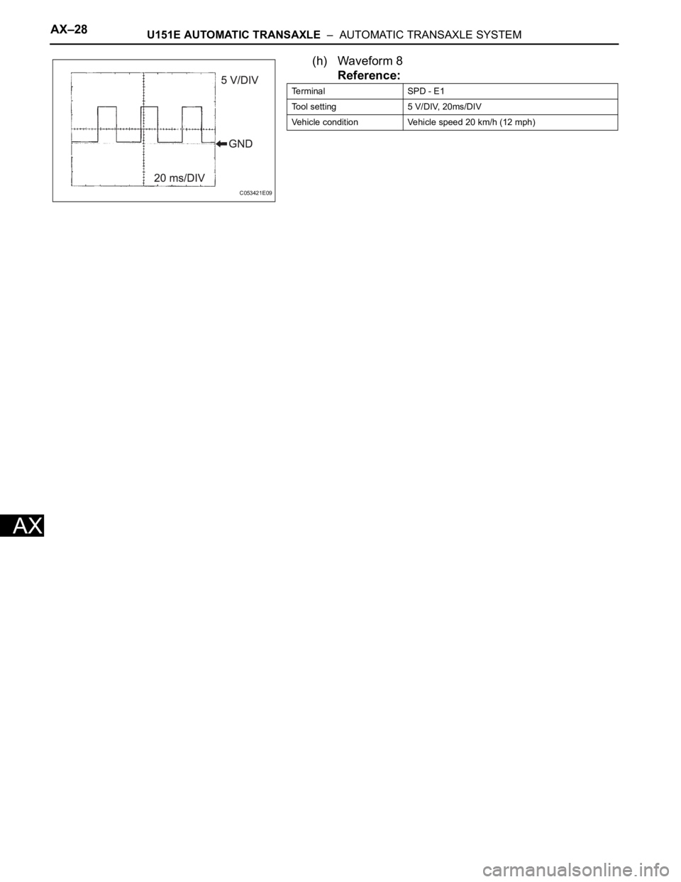
(h) Waveform 8
Reference:
C053421E09
Terminal SPD - E1
Tool setting 5 V/DIV, 20ms/DIV
Vehicle condition Vehicle speed 20 km/h (12 mph)
Page 1534 of 3000
AX–146U151E AUTOMATIC TRANSAXLE – SHIFT LEVER
AX
REMOVAL
1. DISCONNECT BATTERY NEGATIVE TERMINAL
2. REMOVE FRONT DOOR SCUFF PLATE LH
HINT:
(See page IP-6)
3. REMOVE FRONT DOOR SCUFF PLATE RH
HINT:
(See page IP-6)
4. REMOVE COWL SIDE TRIM BOARD LH
HINT:
(See page IP-6)
5. REMOVE COWL SIDE TRIM BOARD RH
HINT:
(See page IP-6)
6. REMOVE INSTRUMENT PANEL FINISH PANEL SUB-
ASSEMBLY LOWER LH
HINT:
(See page IP-6)
7. REMOVE GLOVE COMPARTMENT DOOR STOPPER
SUB-ASSEMBLY
HINT:
(See page IP-7)
8. REMOVE GLOVE COMPARTMENT DOOR
ASSEMBLY
HINT:
(See page IP-7)
9. REMOVE FLOOR CARPET COVER CENTER LH
HINT:
(See page IP-8)
10. REMOVE FLOOR CARPET COVER CENTER RH
HINT:
(See page IP-8)
11. REMOVE INSTRUMENT CLUSTER FINISH PANEL
CENTER NO.1
HINT:
(See page IP-8)
12. REMOVE INSTRUMENT CLUSTER FINISH PANEL
CENTER NO.2
HINT:
(See page IP-8)
Page 1535 of 3000
U151E AUTOMATIC TRANSAXLE – SHIFT LEVERAX–147
AX
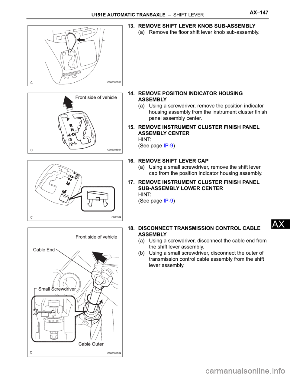
13. REMOVE SHIFT LEVER KNOB SUB-ASSEMBLY
(a) Remove the floor shift lever knob sub-assembly.
14. REMOVE POSITION INDICATOR HOUSING
ASSEMBLY
(a) Using a screwdriver, remove the position indicator
housing assembly from the instrument cluster finish
panel assembly center.
15. REMOVE INSTRUMENT CLUSTER FINISH PANEL
ASSEMBLY CENTER
HINT:
(See page IP-9)
16. REMOVE SHIFT LEVER CAP
(a) Using a small screwdriver, remove the shift lever
cap from the position indicator housing assembly.
17. REMOVE INSTRUMENT CLUSTER FINISH PANEL
SUB-ASSEMBLY LOWER CENTER
HINT:
(See page IP-9)
18. DISCONNECT TRANSMISSION CONTROL CABLE
ASSEMBLY
(a) Using a screwdriver, disconnect the cable end from
the shift lever assembly.
(b) Using a small screwdriver, disconnect the outer of
transmission control cable assembly from the shift
lever assembly.
C086302E01
C086303E01
C086304
C086305E04
Page 1536 of 3000
AX–148U151E AUTOMATIC TRANSAXLE – SHIFT LEVER
AX
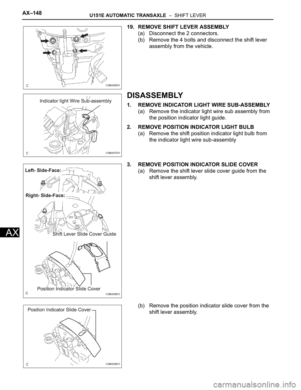
19. REMOVE SHIFT LEVER ASSEMBLY
(a) Disconnect the 2 connectors.
(b) Remove the 4 bolts and disconnect the shift lever
assembly from the vehicle.
DISASSEMBLY
1. REMOVE INDICATOR LIGHT WIRE SUB-ASSEMBLY
(a) Remove the indicator light wire sub assembly from
the position indicator light guide.
2. REMOVE POSITION INDICATOR LIGHT BULB
(a) Remove the shift position indicator light bulb from
the indicator light wire sub-assembly
3. REMOVE POSITION INDICATOR SLIDE COVER
(a) Remove the shift lever slide cover guide from the
shift lever assembly.
(b) Remove the position indicator slide cover from the
shift lever assembly.
C086306E01
C086307E01
C086308E01
C086309E01
Page 1537 of 3000
U151E AUTOMATIC TRANSAXLE – SHIFT LEVERAX–149
AX
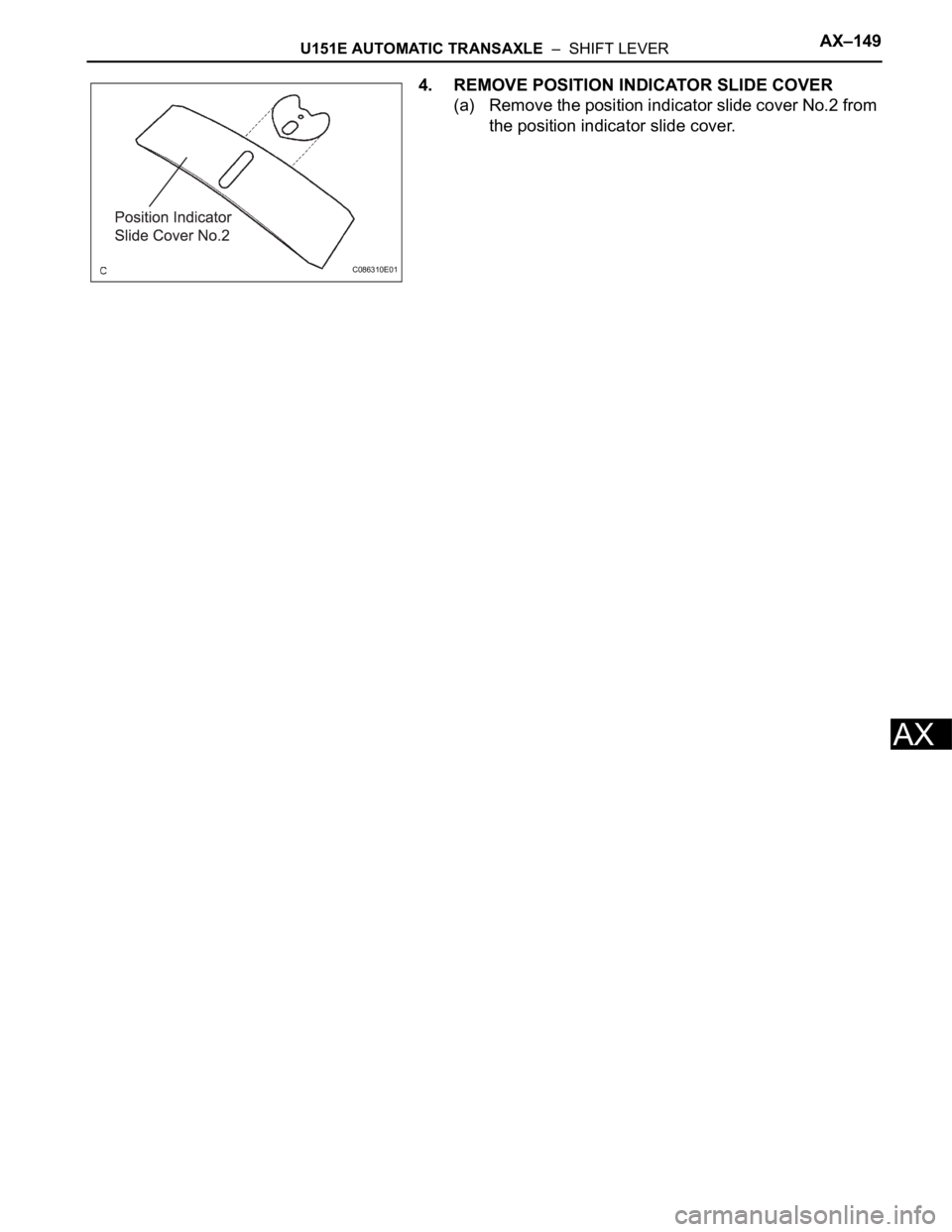
4. REMOVE POSITION INDICATOR SLIDE COVER
(a) Remove the position indicator slide cover No.2 from
the position indicator slide cover.
C086310E01
Page 1538 of 3000
AX–150U151E AUTOMATIC TRANSAXLE – SHIFT LEVER
AX
ADJUSTMENT
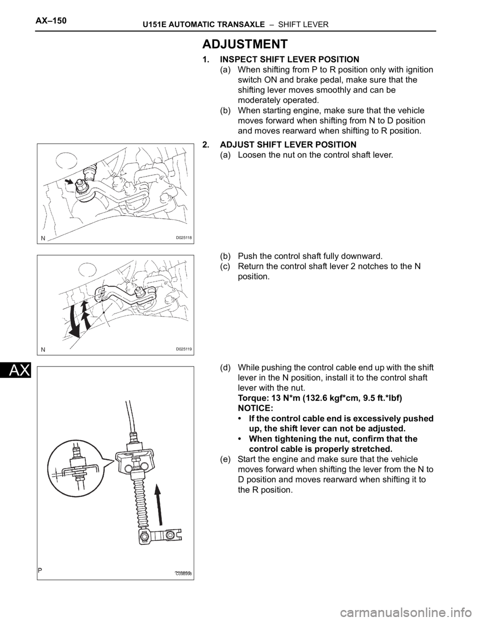
1. INSPECT SHIFT LEVER POSITION
(a) When shifting from P to R position only with ignition
switch ON and brake pedal, make sure that the
shifting lever moves smoothly and can be
moderately operated.
(b) When starting engine, make sure that the vehicle
moves forward when shifting from N to D position
and moves rearward when shifting to R position.
2. ADJUST SHIFT LEVER POSITION
(a) Loosen the nut on the control shaft lever.
(b) Push the control shaft fully downward.
(c) Return the control shaft lever 2 notches to the N
position.
(d) While pushing the control cable end up with the shift
lever in the N position, install it to the control shaft
lever with the nut.
Torque: 13 N*m (132.6 kgf*cm, 9.5 ft.*lbf)
NOTICE:
• If the control cable end is excessively pushed
up, the shift lever can not be adjusted.
• When tightening the nut, confirm that the
control cable is properly stretched.
(e) Start the engine and make sure that the vehicle
moves forward when shifting the lever from the N to
D position and moves rearward when shifting it to
the R position.
D025118
D025119
C098998
Page 1539 of 3000
U151E AUTOMATIC TRANSAXLE – SHIFT LEVERAX–151
AX
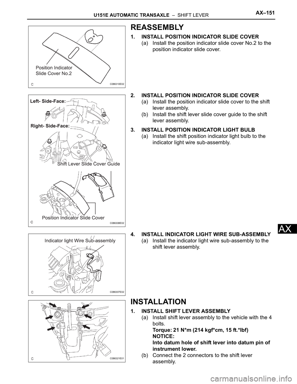
REASSEMBLY
1. INSTALL POSITION INDICATOR SLIDE COVER
(a) Install the position indicator slide cover No.2 to the
position indicator slide cover.
2. INSTALL POSITION INDICATOR SLIDE COVER
(a) Install the position indicator slide cover to the shift
lever assembly.
(b) Install the shift lever slide cover guide to the shift
lever assembly.
3. INSTALL POSITION INDICATOR LIGHT BULB
(a) Install the shift position indicator light bulb to the
indicator light wire sub-assembly.
4. INSTALL INDICATOR LIGHT WIRE SUB-ASSEMBLY
(a) Install the indicator light wire sub-assembly to the
shift lever assembly.
INSTALLATION
1. INSTALL SHIFT LEVER ASSEMBLY
(a) Install shift lever assembly to the vehicle with the 4
bolts.
Torque: 21 N*m (214 kgf*cm, 15 ft.*lbf)
NOTICE:
Into datum hole of shift lever into datum pin of
instrument lower.
(b) Connect the 2 connectors to the shift lever
assembly.
C086310E02
C086308E02
C086307E02
C086321E01
Page 1540 of 3000
AX–152U151E AUTOMATIC TRANSAXLE – SHIFT LEVER
AX
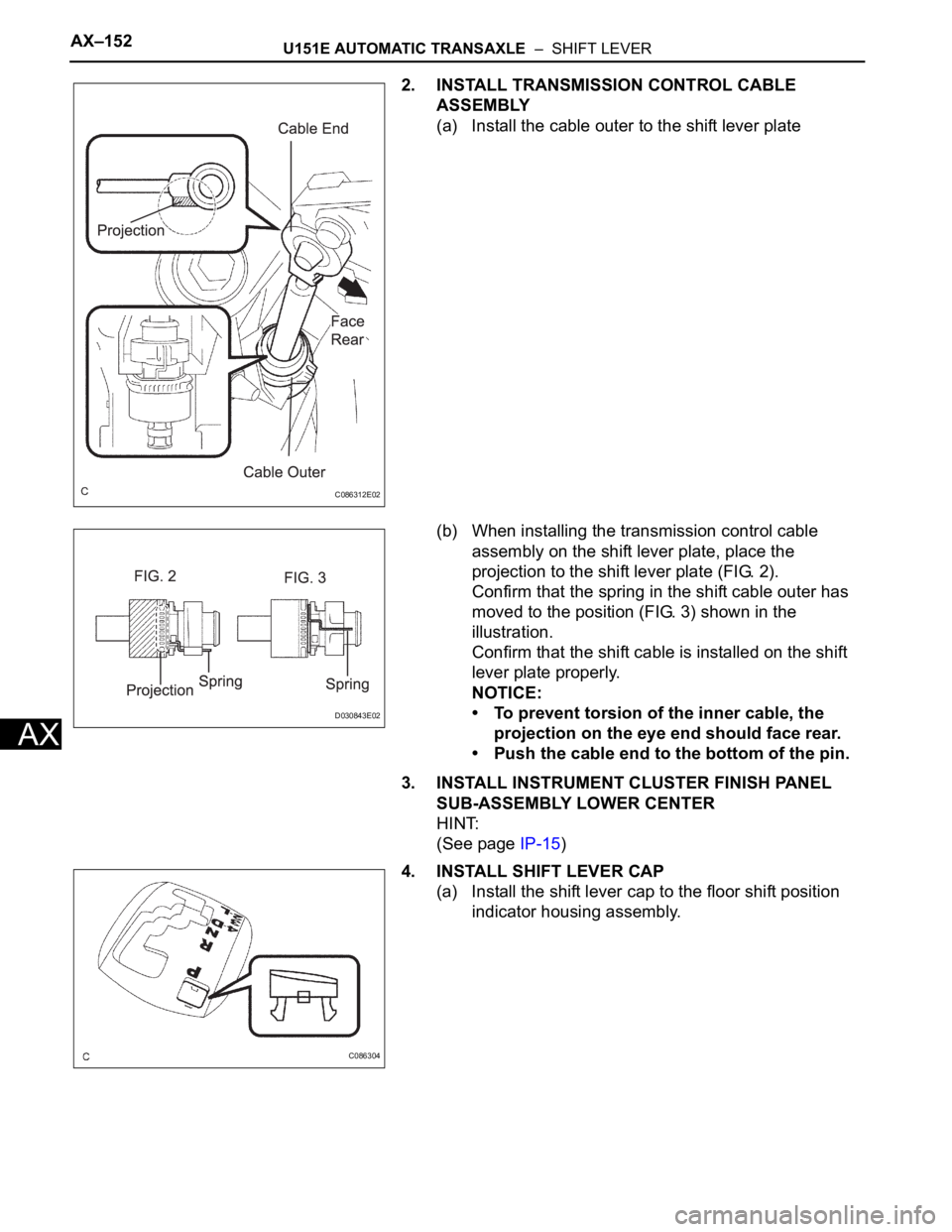
2. INSTALL TRANSMISSION CONTROL CABLE
ASSEMBLY
(a) Install the cable outer to the shift lever plate
(b) When installing the transmission control cable
assembly on the shift lever plate, place the
projection to the shift lever plate (FIG. 2).
Confirm that the spring in the shift cable outer has
moved to the position (FIG. 3) shown in the
illustration.
Confirm that the shift cable is installed on the shift
lever plate properly.
NOTICE:
• To prevent torsion of the inner cable, the
projection on the eye end should face rear.
• Push the cable end to the bottom of the pin.
3. INSTALL INSTRUMENT CLUSTER FINISH PANEL
SUB-ASSEMBLY LOWER CENTER
HINT:
(See page IP-15)
4. INSTALL SHIFT LEVER CAP
(a) Install the shift lever cap to the floor shift position
indicator housing assembly.
C086312E02
D030843E02
C086304