TOYOTA SIENNA 2007 Service Repair Manual
Manufacturer: TOYOTA, Model Year: 2007, Model line: SIENNA, Model: TOYOTA SIENNA 2007Pages: 3000, PDF Size: 52.26 MB
Page 2581 of 3000
BC–198BRAKE CONTROL – YAW RATE AND DECELERATION SENSOR
BC
INSTALLATION
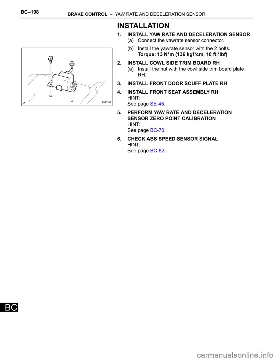
1. INSTALL YAW RATE AND DECELERATION SENSOR
(a) Connect the yawrate sensor connector.
(b) Install the yawrate sensor with the 2 bolts.
Torque: 13 N*m (136 kgf*cm, 10 ft.*lbf)
2. INSTALL COWL SIDE TRIM BOARD RH
(a) Install the nut with the cowl side trim board plate
RH.
3. INSTALL FRONT DOOR SCUFF PLATE RH
4. INSTALL FRONT SEAT ASSEMBLY RH
HINT:
See page SE-45.
5. PERFORM YAW RATE AND DECELERATION
SENSOR ZERO POINT CALIBRATION
HINT:
See page BC-70.
6. CHECK ABS SPEED SENSOR SIGNAL
HINT:
See page BC-82.
F045357
Page 2582 of 3000
BRAKE CONTROL – ANTI-LOCK BRAKE SYSTEMBC–39
BC
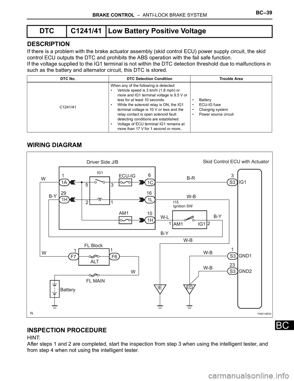
DESCRIPTION
If there is a problem with the brake actuator assembly (skid control ECU) power supply circuit, the skid
control ECU outputs the DTC and prohibits the ABS operation with the fail safe function.
If the voltage supplied to the IG1 terminal is not within the DTC detection threshold due to malfunctions in
such as the battery and alternator circuit, this DTC is stored.
WIRING DIAGRAM
INSPECTION PROCEDURE
HINT:
After steps 1 and 2 are completed, start the inspection from step 3 when using the intelligent tester, and
from step 4 when not using the intelligent tester.
DTC C1241/41 Low Battery Positive Voltage
DTC No. DTC Detection Condition Trouble Area
C1241/41When any of the following is detected:
• Vehicle speed is 3 km/h (1.8 mph) or
more and IG1 terminal voltage is 9.5 V or
less for at least 10 seconds.
• While the solenoid relay is ON, the IG1
terminal voltage is 10 V or less and the
relay contact is open solenoid fault
detecting conditions are established.
• Voltage of ECU terminal IG1 remains at
more than 17 V for 1 second or more..• Battery
•ECU-IG fuse
• Charging system
• Power source circuit
F045116E05
Page 2583 of 3000
BC–40BRAKE CONTROL – ANTI-LOCK BRAKE SYSTEM
BC
(a) Check the battery voltage.
Standard voltage:
11 to 14 V
NG
OK
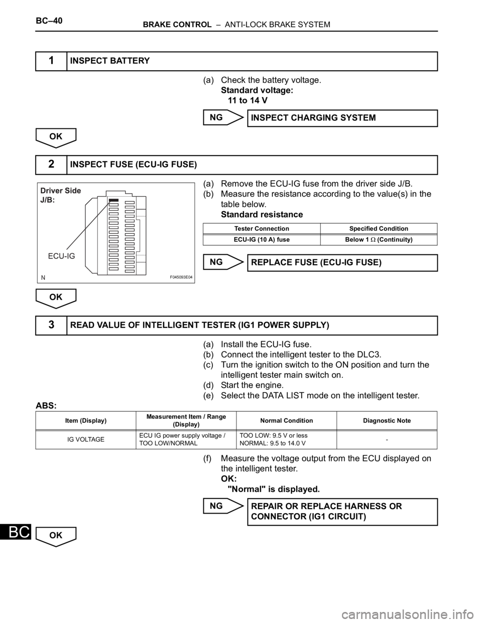
(a) Remove the ECU-IG fuse from the driver side J/B.
(b) Measure the resistance according to the value(s) in the
table below.
Standard resistance
NG
OK
(a) Install the ECU-IG fuse.
(b) Connect the intelligent tester to the DLC3.
(c) Turn the ignition switch to the ON position and turn the
intelligent tester main switch on.
(d) Start the engine.
(e) Select the DATA LIST mode on the intelligent tester.
ABS:
(f) Measure the voltage output from the ECU displayed on
the intelligent tester.
OK:
"Normal" is displayed.
NG
OK
1INSPECT BATTERY
INSPECT CHARGING SYSTEM
2INSPECT FUSE (ECU-IG FUSE)
F045093E04
Tester Connection Specified Condition
ECU-IG (10 A) fuse Below 1
(Continuity)
REPLACE FUSE (ECU-IG FUSE)
3READ VALUE OF INTELLIGENT TESTER (IG1 POWER SUPPLY)
Item (Display)Measurement Item / Range
(Display)Normal Condition Diagnostic Note
IG VOLTAGEECU IG power supply voltage /
TOO LOW/NORMALTOO LOW: 9.5 V or less
NORMAL: 9.5 to 14.0 V-
REPAIR OR REPLACE HARNESS OR
CONNECTOR (IG1 CIRCUIT)
Page 2584 of 3000
BRAKE CONTROL – ANTI-LOCK BRAKE SYSTEMBC–41
BC
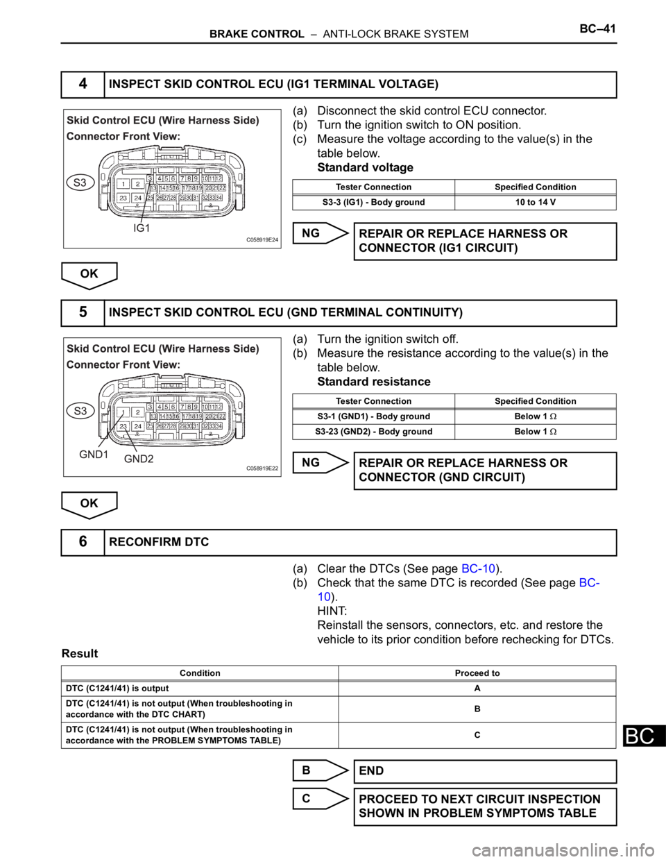
(a) Disconnect the skid control ECU connector.
(b) Turn the ignition switch to ON position.
(c) Measure the voltage according to the value(s) in the
table below.
Standard voltage
NG
OK
(a) Turn the ignition switch off.
(b) Measure the resistance according to the value(s) in the
table below.
Standard resistance
NG
OK
(a) Clear the DTCs (See page BC-10).
(b) Check that the same DTC is recorded (See page BC-
10).
HINT:
Reinstall the sensors, connectors, etc. and restore the
vehicle to its prior condition before rechecking for DTCs.
Result
B
C
4INSPECT SKID CONTROL ECU (IG1 TERMINAL VOLTAGE)
C058919E24
Tester Connection Specified Condition
S3-3 (IG1) - Body ground 10 to 14 V
REPAIR OR REPLACE HARNESS OR
CONNECTOR (IG1 CIRCUIT)
5INSPECT SKID CONTROL ECU (GND TERMINAL CONTINUITY)
C058919E22
Tester Connection Specified Condition
S3-1 (GND1) - Body ground Below 1
S3-23 (GND2) - Body ground Below 1
REPAIR OR REPLACE HARNESS OR
CONNECTOR (GND CIRCUIT)
6RECONFIRM DTC
Condition Proceed to
DTC (C1241/41) is outputA
DTC (C1241/41) is not output (When troubleshooting in
accordance with the DTC CHART)B
DTC (C1241/41) is not output (When troubleshooting in
accordance with the PROBLEM SYMPTOMS TABLE)C
END
PROCEED TO NEXT CIRCUIT INSPECTION
SHOWN IN PROBLEM SYMPTOMS TABLE
Page 2585 of 3000

BC–42BRAKE CONTROL – ANTI-LOCK BRAKE SYSTEM
BC
A
REPLACE BRAKE ACTUATOR ASSEMBLY
Page 2586 of 3000
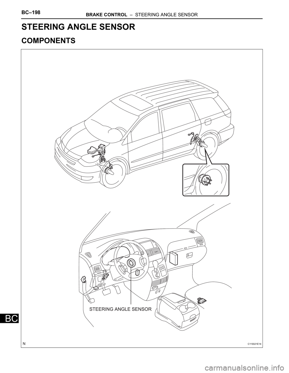
BC–198BRAKE CONTROL – STEERING ANGLE SENSOR
BC
BRAKE
BRAKE CONTROL
STEERING ANGLE SENSOR
COMPONENTS
C119321E14
Page 2587 of 3000
BRAKE CONTROL – STEERING ANGLE SENSORBC–199
BC
REMOVAL
1. PRECAUTION
HINT:
See page RS-1
2. SEPARATE BATTERY NEGATIVE TERMINAL
3. PLACE FRONT WHEELS FACING STRAIGHT AHEAD
4. REMOVE HORN BUTTON ASSEMBLY (See page RS-
424)
5. REMOVE STEERING WHEEL ASSEMBLY (See page
SR-6)
6. REMOVE STEERING COLUMN COVER LWR (See
page RS-434)
7. REMOVE SPIRAL CABLE SUB-ASSEMBLY (See page
RS-434)
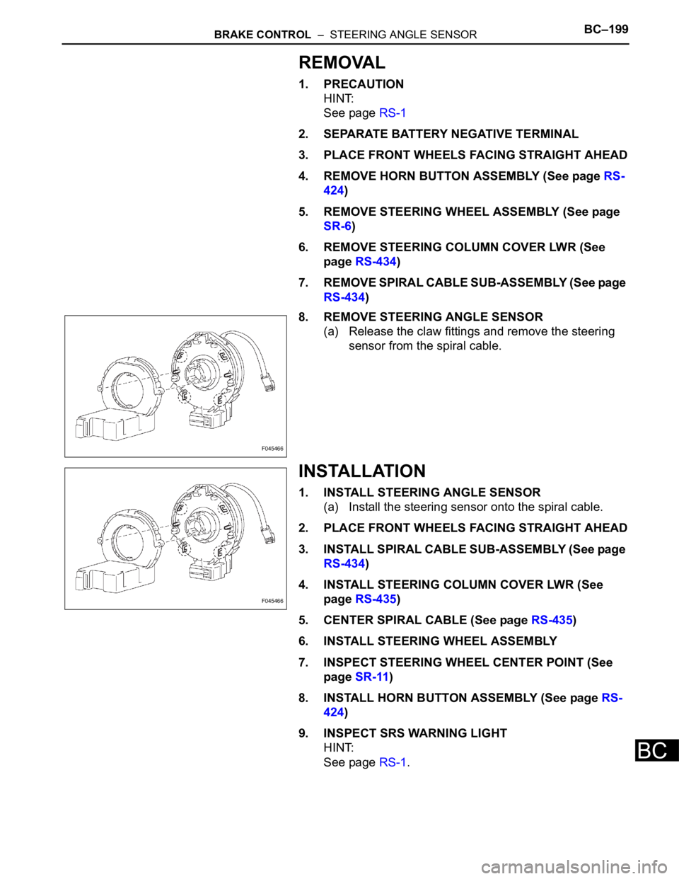
8. REMOVE STEERING ANGLE SENSOR
(a) Release the claw fittings and remove the steering
sensor from the spiral cable.
INSTALLATION
1. INSTALL STEERING ANGLE SENSOR
(a) Install the steering sensor onto the spiral cable.
2. PLACE FRONT WHEELS FACING STRAIGHT AHEAD
3. INSTALL SPIRAL CABLE SUB-ASSEMBLY (See page
RS-434)
4. INSTALL STEERING COLUMN COVER LWR (See
page RS-435)
5. CENTER SPIRAL CABLE (See page RS-435)
6. INSTALL STEERING WHEEL ASSEMBLY
7. INSPECT STEERING WHEEL CENTER POINT (See
page SR-11)
8. INSTALL HORN BUTTON ASSEMBLY (See page RS-
424)
9. INSPECT SRS WARNING LIGHT
HINT:
See page RS-1.
F045466
F045466
Page 2588 of 3000

BRAKE – BRAKE PEDALBR–13
BR
REASSEMBLY
1. INSTALL BRAKE PEDAL PAD
(a) Install the brake pedal pad to the brake pedal sub-
assembly.
2. INSTALL PUSH ROD PIN
(a) Apply lithium soap base glycol grease to inside
surface of 2 new push rod bushes.
(b) Install the 2 new push rod bushes.
(c) Install the 2 push rod pins with the 2 plate to the
brake pedal.
(d) Using needle-nose pliers, install the 2 new E-rings
to the 2 push rod pins.
NOTICE:
Install the E-ring securely to the grooves of the
push rod pin.
3. INSTALL BRAKE PEDAL BUSH
(a) Apply lithium soap base glycol grease to inside
surface of 4 new brake pedal bushes.
(b) Install the 4 brake pedal bushes to the brake pedal.
4. INSTALL BRAKE PEDAL SHAFT COLLAR
(a) Apply the lithium soap base glycol grease to inside
surface of 2 brake pedal shaft collars.
(b) Install the 2 brake pedal shaft collars to the brake
pedal.
5. INSTALL BRAKE PEDAL
(a) Install the 2 brake pedal shafts, 2 nuts, brake pedal
and brake pedal bracket No. 3 to the brake pedal
support sub-assembly.
6. INSTALL STOP LIGHT SWITCH CUSHION
(a) Install the stop light switch cushion to the brake
pedal sub-assembly.
7. INSTALL STOP LIGHT SWITCH ASSEMBLY
(a) Install the stop light switch mounting adjuster to the
brake pedal support sub-assembly.
(b) Install the stop light switch assembly until the body
hits the cushion.
(c) Make a quarter turn clockwise to install the stop light
switch assembly.
NOTICE:
The turning torque for installing the stop light
switch assembly.
Torque: 1.5 N*m (15 kgf*cm, 13 in.*lbf) or less
HINT:
Due to the inverse screw structure, if the stop light
switch assembly is turned clockwise, the stop light
switch assembly moves in the direction to be pulled
out.
Page 2589 of 3000
BR–14BRAKE – BRAKE PEDAL
BR
INSTALLATION
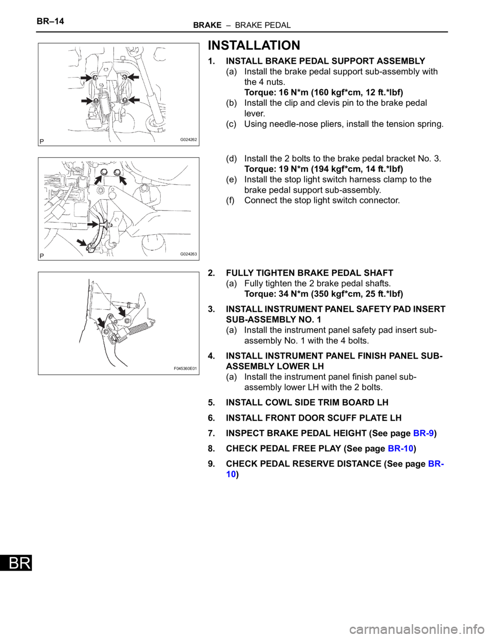
1. INSTALL BRAKE PEDAL SUPPORT ASSEMBLY
(a) Install the brake pedal support sub-assembly with
the 4 nuts.
Torque: 16 N*m (160 kgf*cm, 12 ft.*lbf)
(b) Install the clip and clevis pin to the brake pedal
lever.
(c) Using needle-nose pliers, install the tension spring.
(d) Install the 2 bolts to the brake pedal bracket No. 3.
Torque: 19 N*m (194 kgf*cm, 14 ft.*lbf)
(e) Install the stop light switch harness clamp to the
brake pedal support sub-assembly.
(f) Connect the stop light switch connector.
2. FULLY TIGHTEN BRAKE PEDAL SHAFT
(a) Fully tighten the 2 brake pedal shafts.
Torque: 34 N*m (350 kgf*cm, 25 ft.*lbf)
3. INSTALL INSTRUMENT PANEL SAFETY PAD INSERT
SUB-ASSEMBLY NO. 1
(a) Install the instrument panel safety pad insert sub-
assembly No. 1 with the 4 bolts.
4. INSTALL INSTRUMENT PANEL FINISH PANEL SUB-
ASSEMBLY LOWER LH
(a) Install the instrument panel finish panel sub-
assembly lower LH with the 2 bolts.
5. INSTALL COWL SIDE TRIM BOARD LH
6. INSTALL FRONT DOOR SCUFF PLATE LH
7. INSPECT BRAKE PEDAL HEIGHT (See page BR-9)
8. CHECK PEDAL FREE PLAY (See page BR-10)
9. CHECK PEDAL RESERVE DISTANCE (See page BR-
10)
G024262
G024263
F045360E01
Page 2590 of 3000
BR–16BRAKE – BRAKE MASTER CYLINDER
BR
DISASSEMBLY
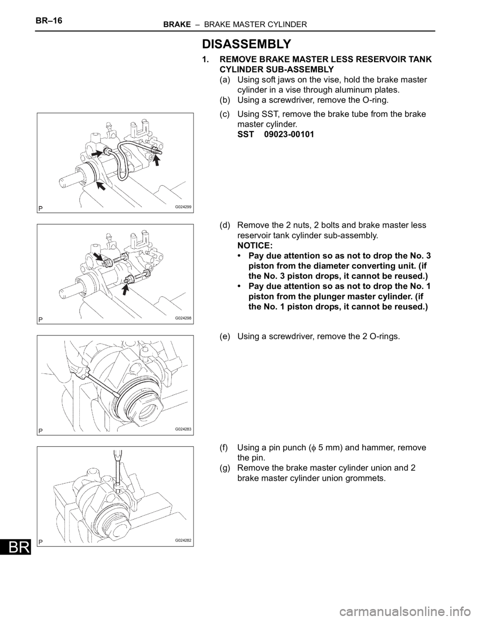
1. REMOVE BRAKE MASTER LESS RESERVOIR TANK
CYLINDER SUB-ASSEMBLY
(a) Using soft jaws on the vise, hold the brake master
cylinder in a vise through aluminum plates.
(b) Using a screwdriver, remove the O-ring.
(c) Using SST, remove the brake tube from the brake
master cylinder.
SST 09023-00101
(d) Remove the 2 nuts, 2 bolts and brake master less
reservoir tank cylinder sub-assembly.
NOTICE:
• Pay due attention so as not to drop the No. 3
piston from the diameter converting unit. (if
the No. 3 piston drops, it cannot be reused.)
• Pay due attention so as not to drop the No. 1
piston from the plunger master cylinder. (if
the No. 1 piston drops, it cannot be reused.)
(e) Using a screwdriver, remove the 2 O-rings.
(f) Using a pin punch (
5 mm) and hammer, remove
the pin.
(g) Remove the brake master cylinder union and 2
brake master cylinder union grommets.
G024299
G024298
G024283
G024282