oil pressure TOYOTA SIENNA 2007 Service Service Manual
[x] Cancel search | Manufacturer: TOYOTA, Model Year: 2007, Model line: SIENNA, Model: TOYOTA SIENNA 2007Pages: 3000, PDF Size: 52.26 MB
Page 1299 of 3000
2GR-FE LUBRICATION – LUBRICATION SYSTEMLU–1
LU
LUBRICATION SYSTEM
ON-VEHICLE INSPECTION
1. CHECK ENGINE OIL LEVEL
(a) Warm up the engine, stop it and wait 5 minutes. The
oil level should be between the dipstick's low level
mark and full level mark.
If the engine oil level is low, check for leakage and
add oil up to the full level mark.
NOTICE:
Do not add engine oil above the full level mark.
2. CHECK ENGINE OIL
(a) Check the engine oil for deterioration, water
contamination, discoloring or thinning.
If the oil is bad, replace the engine oil and engine oil
filter.
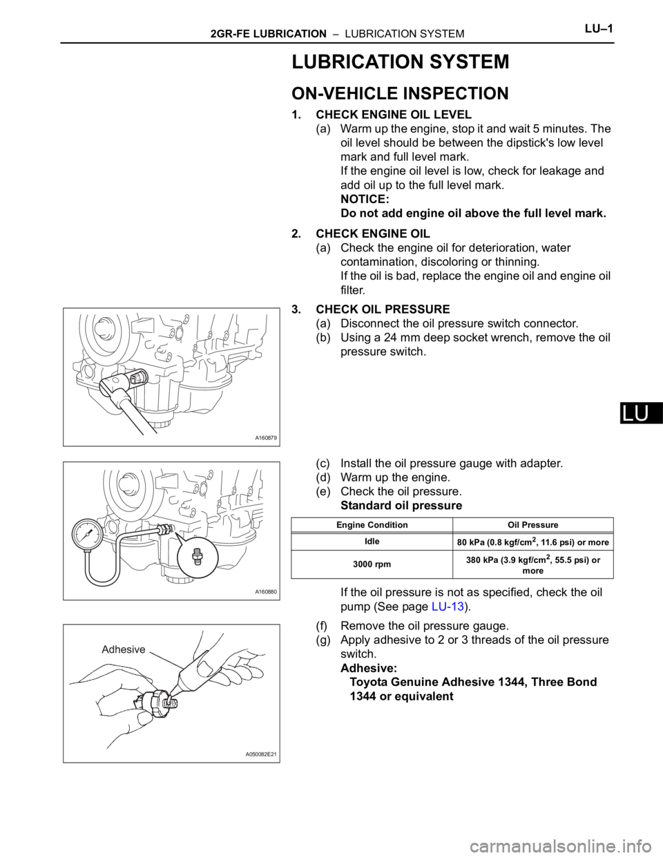
3. CHECK OIL PRESSURE
(a) Disconnect the oil pressure switch connector.
(b) Using a 24 mm deep socket wrench, remove the oil
pressure switch.
(c) Install the oil pressure gauge with adapter.
(d) Warm up the engine.
(e) Check the oil pressure.
Standard oil pressure
If the oil pressure is not as specified, check the oil
pump (See page LU-13).
(f) Remove the oil pressure gauge.
(g) Apply adhesive to 2 or 3 threads of the oil pressure
switch.
Adhesive:
Toyota Genuine Adhesive 1344, Three Bond
1344 or equivalent
A160879
A160880
Engine Condition Oil Pressure
Idle
80 kPa (0.8 kgf/cm
2, 11.6 psi) or more
3000 rpm380 kPa (3.9 kgf/cm
2, 55.5 psi) or
more
A050082E21
Page 1300 of 3000
LU–22GR-FE LUBRICATION – LUBRICATION SYSTEM
LU
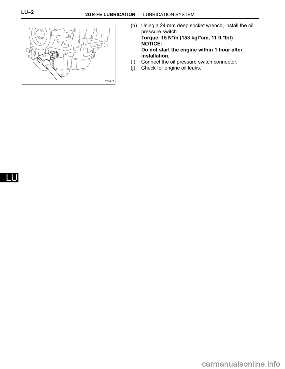
(h) Using a 24 mm deep socket wrench, install the oil
pressure switch.
Torque: 15 N*m (153 kgf*cm, 11 ft.*lbf)
NOTICE:
Do not start the engine within 1 hour after
installation.
(i) Connect the oil pressure switch connector.
(j) Check for engine oil leaks.
A160879
Page 1317 of 3000
IG–82GR-FE IGNITION – IGNITION COIL AND SPARK PLUG
IG
(2) Remove the spark plugs.
(3) Visually check the spark plug.
If the electrode is dry, the spark plug is
functioning properly. If the electrode is damp,
proceed to the next step.
(c) Check the spark plug for any damage to its threads
and insulator. If there is damage, replace the spark
plug.
Recommended spark plug
NOTICE:
Use only the listed spark plug or equivalent to
ensure engine performance and smooth
driveability.
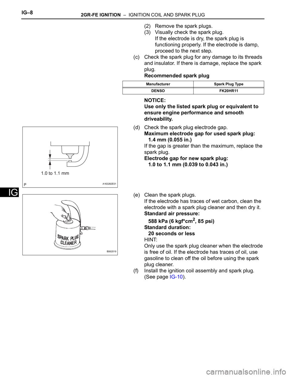
(d) Check the spark plug electrode gap.
Maximum electrode gap for used spark plug:
1.4 mm (0.055 in.)
If the gap is greater than the maximum, replace the
spark plug.
Electrode gap for new spark plug:
1.0 to 1.1 mm (0.039 to 0.043 in.)
(e) Clean the spark plugs.
If the electrode has traces of wet carbon, clean the
electrode with a spark plug cleaner and then dry it.
Standard air pressure:
588 kPa (6 kgf*cm
2, 85 psi)
Standard duration:
20 seconds or less
HINT:
Only use the spark plug cleaner when the electrode
is free of oil. If the electrode has traces of oil, use
gasoline to clean off the oil before using the spark
plug cleaner.
(f) Install the ignition coil assembly and spark plug.
(See page IG-10).
Manufacturer Spark Plug Type
DENSO FK20HR11
A163282E01
B062019
Page 1351 of 3000
CH–162GR-FE CHARGING – GENERATOR
CH
REMOVAL
1. REMOVE V-BANK COVER SUB-ASSEMBLY (See
page EM-28)
2. REMOVE FRONT WHEEL RH
3. REMOVE NO. 1 ENGINE UNDER COVER (See page
EM-26)
4. REMOVE FRONT FENDER APRON SEAL RH (See
page EM-26)
5. DRAIN ENGINE COOLANT (See page CO-6)
6. REMOVE NO. 2 AIR CLEANER INLET (See page EM-
28)
7. REMOVE BATTERY (See page EM-26)
8. REMOVE FRONT BUMPER ASSEMBLY (See page
ET-3)
9. REMOVE FRONT BUMPER ENERGY ABSORBER
10. REMOVE NO. 1 AIR CLEANER INLET (See page EM-
28)
11. DISCONNECT RADIATOR RESERVE TANK HOSE OR
PIPE (See page CO-28)
12. DISCONNECT NO. 1 RADIATOR HOSE (See page CO-
28)
13. DISCONNECT NO. 2 RADIATOR HOSE (See page CO-
29)
14. REMOVE HOOD LOCK RELEASE LEVER
PROTECTOR (See page CO-29)
15. REMOVE HOOD LOCK ASSEMBLY (See page CO-29)
16. REMOVE HOOD LOCK SUPPORT SUB-ASSEMBLY
(See page CO-29)
17. DISCONNECT COOLING FAN ECU CONNECTOR
(See page CO-30)
18. REMOVE RADIATOR UPPER SUPPORT SUB-
ASSEMBLY (See page CO-30)
19. DISCONNECT NO. 2 OIL COOLER OUTLET TUBE
SUB-ASSEMBLY (See page CO-31)
20. REMOVE HEADLIGHT ASSEMBLY RH (See page LI-
69)
21. REMOVE RADIATOR SIDE DEFLECTOR RH (See
page CO-31)
22. REMOVE HEADLIGHT BRACKET RH (See page CO-
32)
23. REMOVE PRESSURE FEED TUBE ASSEMBLY (See
page CO-32)
Page 1356 of 3000
CH–162GR-FE CHARGING – GENERATOR
CH
REMOVAL
1. REMOVE V-BANK COVER SUB-ASSEMBLY (See
page EM-28)
2. REMOVE FRONT WHEEL RH
3. REMOVE NO. 1 ENGINE UNDER COVER (See page
EM-26)
4. REMOVE FRONT FENDER APRON SEAL RH (See
page EM-26)
5. DRAIN ENGINE COOLANT (See page CO-6)
6. REMOVE NO. 2 AIR CLEANER INLET (See page EM-
28)
7. REMOVE BATTERY (See page EM-26)
8. REMOVE FRONT BUMPER ASSEMBLY (See page
ET-3)
9. REMOVE FRONT BUMPER ENERGY ABSORBER
10. REMOVE NO. 1 AIR CLEANER INLET (See page EM-
28)
11. DISCONNECT RADIATOR RESERVE TANK HOSE OR
PIPE (See page CO-28)
12. DISCONNECT NO. 1 RADIATOR HOSE (See page CO-
28)
13. DISCONNECT NO. 2 RADIATOR HOSE (See page CO-
29)
14. REMOVE HOOD LOCK RELEASE LEVER
PROTECTOR (See page CO-29)
15. REMOVE HOOD LOCK ASSEMBLY (See page CO-29)
16. REMOVE HOOD LOCK SUPPORT SUB-ASSEMBLY
(See page CO-29)
17. DISCONNECT COOLING FAN ECU CONNECTOR
(See page CO-30)
18. REMOVE RADIATOR UPPER SUPPORT SUB-
ASSEMBLY (See page CO-30)
19. DISCONNECT NO. 2 OIL COOLER OUTLET TUBE
SUB-ASSEMBLY (See page CO-31)
20. REMOVE HEADLIGHT ASSEMBLY RH (See page LI-
69)
21. REMOVE RADIATOR SIDE DEFLECTOR RH (See
page CO-31)
22. REMOVE HEADLIGHT BRACKET RH (See page CO-
32)
23. REMOVE PRESSURE FEED TUBE ASSEMBLY (See
page CO-32)
Page 1368 of 3000
CH–282GR-FE CHARGING – GENERATOR
CH
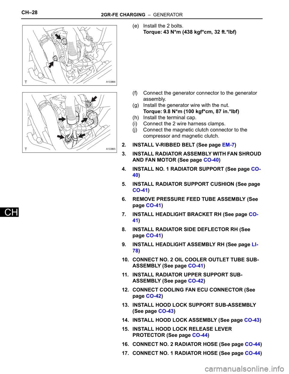
(e) Install the 2 bolts.
Torque: 43 N*m (438 kgf*cm, 32 ft.*lbf)
(f) Connect the generator connector to the generator
assembly.
(g) Install the generator wire with the nut.
Torque: 9.8 N*m (100 kgf*cm, 87 in.*lbf)
(h) Install the terminal cap.
(i) Connect the 2 wire harness clamps.
(j) Connect the magnetic clutch connector to the
compressor and magnetic clutch.
2. INSTALL V-RIBBED BELT (See page EM-7)
3. INSTALL RADIATOR ASSEMBLY WITH FAN SHROUD
AND FAN MOTOR (See page CO-40)
4. INSTALL NO. 1 RADIATOR SUPPORT (See page CO-
40)
5. INSTALL RADIATOR SUPPORT CUSHION (See page
CO-41)
6. REMOVE PRESSURE FEED TUBE ASSEMBLY (See
page CO-41)
7. INSTALL HEADLIGHT BRACKET RH (See page CO-
41)
8. INSTALL RADIATOR SIDE DEFLECTOR RH (See
page CO-41)
9. INSTALL HEADLIGHT ASSEMBLY RH (See page LI-
78)
10. CONNECT NO. 2 OIL COOLER OUTLET TUBE SUB-
ASSEMBLY (See page CO-41)
11. INSTALL RADIATOR UPPER SUPPORT SUB-
ASSEMBLY (See page CO-42)
12. CONNECT COOLING FAN ECU CONNECTOR (See
page CO-42)
13. INSTALL HOOD LOCK SUPPORT SUB-ASSEMBLY
(See page CO-43)
14. INSTALL HOOD LOCK ASSEMBLY (See page CO-43)
15. INSTALL HOOD LOCK RELEASE LEVER
PROTECTOR (See page CO-44)
16. CONNECT NO. 2 RADIATOR HOSE (See page CO-44)
17. CONNECT NO. 1 RADIATOR HOSE (See page CO-44)
A133866
A133865
Page 1377 of 3000
CH–282GR-FE CHARGING – GENERATOR
CH
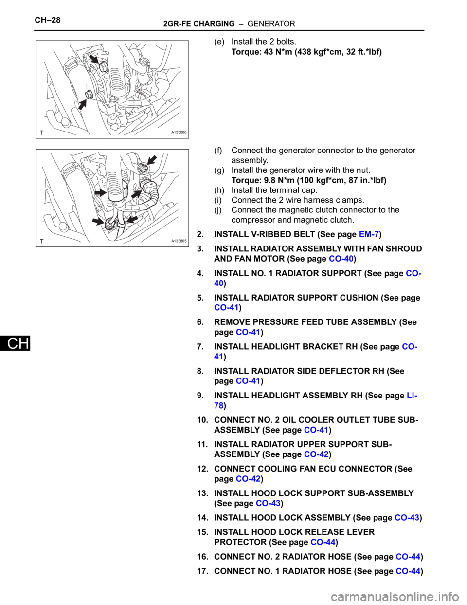
(e) Install the 2 bolts.
Torque: 43 N*m (438 kgf*cm, 32 ft.*lbf)
(f) Connect the generator connector to the generator
assembly.
(g) Install the generator wire with the nut.
Torque: 9.8 N*m (100 kgf*cm, 87 in.*lbf)
(h) Install the terminal cap.
(i) Connect the 2 wire harness clamps.
(j) Connect the magnetic clutch connector to the
compressor and magnetic clutch.
2. INSTALL V-RIBBED BELT (See page EM-7)
3. INSTALL RADIATOR ASSEMBLY WITH FAN SHROUD
AND FAN MOTOR (See page CO-40)
4. INSTALL NO. 1 RADIATOR SUPPORT (See page CO-
40)
5. INSTALL RADIATOR SUPPORT CUSHION (See page
CO-41)
6. REMOVE PRESSURE FEED TUBE ASSEMBLY (See
page CO-41)
7. INSTALL HEADLIGHT BRACKET RH (See page CO-
41)
8. INSTALL RADIATOR SIDE DEFLECTOR RH (See
page CO-41)
9. INSTALL HEADLIGHT ASSEMBLY RH (See page LI-
78)
10. CONNECT NO. 2 OIL COOLER OUTLET TUBE SUB-
ASSEMBLY (See page CO-41)
11. INSTALL RADIATOR UPPER SUPPORT SUB-
ASSEMBLY (See page CO-42)
12. CONNECT COOLING FAN ECU CONNECTOR (See
page CO-42)
13. INSTALL HOOD LOCK SUPPORT SUB-ASSEMBLY
(See page CO-43)
14. INSTALL HOOD LOCK ASSEMBLY (See page CO-43)
15. INSTALL HOOD LOCK RELEASE LEVER
PROTECTOR (See page CO-44)
16. CONNECT NO. 2 RADIATOR HOSE (See page CO-44)
17. CONNECT NO. 1 RADIATOR HOSE (See page CO-44)
A133866
A133865
Page 1393 of 3000
AX–16U151E AUTOMATIC TRANSAXLE – AUTOMATIC TRANSAXLE SYSTEM
AX
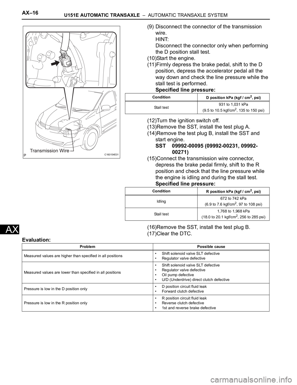
(9) Disconnect the connector of the transmission
wire.
HINT:
Disconnect the connector only when performing
the D position stall test.
(10)Start the engine.
(11)Firmly depress the brake pedal, shift to the D
position, depress the accelerator pedal all the
way down and check the line pressure while the
stall test is performed.
Specified line pressure:
(12)Turn the ignition switch off.
(13)Remove the SST, install the test plug A.
(14)Remove the test plug B, install the SST and
start engine.
SST 09992-00095 (09992-00231, 09992-
00271)
(15)Connect the transmission wire connector,
depress the brake pedal firmly, shift to the R
position and check that the line pressure while
the engine is idling and during the stall test.
Specified line pressure:
(16)Remove the SST, install the test plug B.
(17)Clear the DTC.
Evaluation:
C160154E01
Condition
D position kPa (kgf / cm2, psi)
Stall test931 to 1,031 kPa
(9.5 to 10.5 kgf/cm
2, 135 to 150 psi)
Condition
R position kPa (kgf / cm
2, psi)
Idling672 to 742 kPa
(6.9 to 7.6 kgf/cm
2, 97 to 108 psi)
Stall test1,768 to 1,968 kPa
(18.0 to 20.1 kgf/cm
2, 256 to 285 psi)
Problem Possible cause
Measured values are higher than specified in all positions• Shift solenoid valve SLT defective
• Regulator valve defective
Measured values are lower than specified in all positions• Shift solenoid valve SLT defective
• Regulator valve defective
• Oil pump defective
• U/D (Underdrive) direct clutch defective
Pressure is low in the D position only• D position circuit fluid leak
• Forward clutch defective
Pressure is low in the R position only• R position circuit fluid leak
• Reverse clutch defective
• 1st and reverse brake defective
Page 1483 of 3000
U151E AUTOMATIC TRANSAXLE – AUTOMATIC TRANSAXLE SYSTEMAX–117
AX
SYSTEM DESCRIPTION
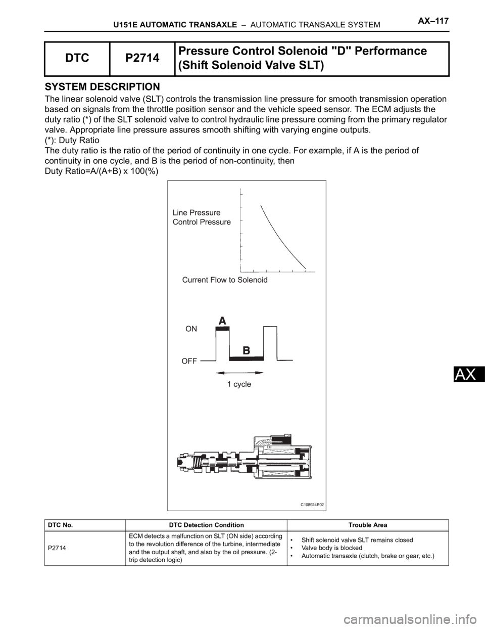
The linear solenoid valve (SLT) controls the transmission line pressure for smooth transmission operation
based on signals from the throttle position sensor and the vehicle speed sensor. The ECM adjusts the
duty ratio (*) of the SLT solenoid valve to control hydraulic line pressure coming from the primary regulator
valve. Appropriate line pressure assures smooth shifting with varying engine outputs.
(*): Duty Ratio
The duty ratio is the ratio of the period of continuity in one cycle. For example, if A is the period of
continuity in one cycle, and B is the period of non-continuity, then
Duty Ratio=A/(A+B) x 100(%)
DTC P2714Pressure Control Solenoid "D" Performance
(Shift Solenoid Valve SLT)
DTC No. DTC Detection Condition Trouble Area
P2714ECM detects a malfunction on SLT (ON side) according
to the revolution difference of the turbine, intermediate
and the output shaft, and also by the oil pressure. (2-
trip detection logic)• Shift solenoid valve SLT remains closed
• Valve body is blocked
• Automatic transaxle (clutch, brake or gear, etc.)
C108924E02
Page 1484 of 3000
AX–118U151E AUTOMATIC TRANSAXLE – AUTOMATIC TRANSAXLE SYSTEM
AX
MONITOR DESCRIPTION
In any forward position, when the difference between the revolutions of the turbine, Intermediate and
output shaft exceeds the specified value (varies with Intermediate, output speed) determined by the ECM,
the ECM illuminates the MIL and store the DTC.
When shift solenoid valve SLT remains on, the oil pressure goes down and the clutch engagement force
decreases.
NOTICE:
If you continue driving under these conditions, the clutch will burn out and the vehicle will no
longer be drivable.
MONITOR STRATEGY
TYPICAL ENABLING CONDITIONS
ON malfunction:
ON malfunction (A):
Related DTCs P2714: Shift solenoid valve SLT/ON malfunction
Required sensors/ComponentsShift solenoid valve SLT, Speed sensor (NT), Speed sensor (NC),
Crankshaft position sensor (NE)
Frequency of operation Continuous
Duration 0.5 sec.
MIL operation 2 driving cycles
Sequence of operation None
The monitor will run whenever this DTC is not present. None
Transmission range"D"
TFT (Transmission fluid temperature) -20
C (-4F) or more
TFT sensor circuitNot circuit malfunction
Turbine speed sensor circuit Not circuit malfunction
Intermediate shaft speed sensor circuit Not circuit malfunction
Output speed sensor circuitNot circuit malfunction
Shift solenoid valve SL1 circuit Not circuit malfunction
Shift solenoid valve SL2 circuit Not circuit malfunction
Shift solenoid valve SL3 circuit Not circuit malfunction
Shift solenoid valve S4 circuit Not circuit malfunction
Shift solenoid valve SR circuit Not circuit malfunction
Shift solenoid valve DSL circuit Not circuit malfunction
Shift solenoid valve SLT circuit Not circuit malfunction
Electronic throttle systemNot circuit malfunction
ECM selected gear 1st
Temporary MAIN gear 1st or 2nd or 3rd or 4th
NT - NC x Temporary MAIN gear ratio
NT: Input (turbine) speed
NC: Intermediate shaft speed100 rpm or more at Intermediate shaft speed 1,000 rpm
Temporary U/D gear Low
NC - NO x Temporary U/D gear ratio
NO: Output speed300 rpm or more at Output speed 1,000 rpm
TT
TT: Turbine Torque900 Nm or more
NT 250 rpm or more
NC 250 rpm or more
NO 250 rpm or more