engine oil TOYOTA SIENNA 2007 Service Workshop Manual
[x] Cancel search | Manufacturer: TOYOTA, Model Year: 2007, Model line: SIENNA, Model: TOYOTA SIENNA 2007Pages: 3000, PDF Size: 52.26 MB
Page 511 of 3000
2GR-FE ENGINE CONTROL SYSTEM – SFI SYSTEMES–205
ES
When multiple DTCs for misfiring cylinders are set, but DTC P0300 is not set, it indicates that misfires
have been detected in different cylinders at different times. DTC P0300 is only set when several misfiring
cylinders are detected at the same time.
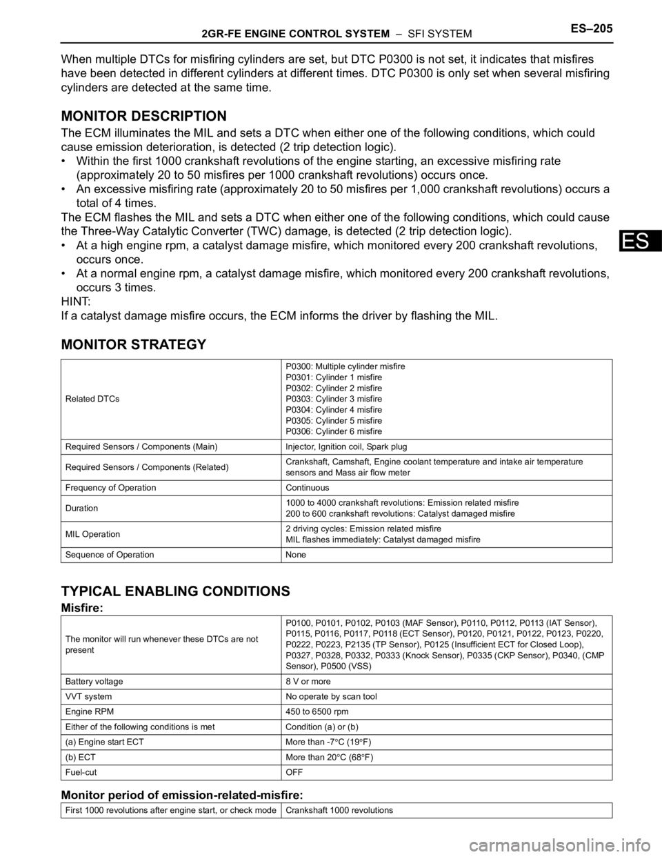
MONITOR DESCRIPTION
The ECM illuminates the MIL and sets a DTC when either one of the following conditions, which could
cause emission deterioration, is detected (2 trip detection logic).
• Within the first 1000 crankshaft revolutions of the engine starting, an excessive misfiring rate
(approximately 20 to 50 misfires per 1000 crankshaft revolutions) occurs once.
• An excessive misfiring rate (approximately 20 to 50 misfires per 1,000 crankshaft revolutions) occurs a
total of 4 times.
The ECM flashes the MIL and sets a DTC when either one of the following conditions, which could cause
the Three-Way Catalytic Converter (TWC) damage, is detected (2 trip detection logic).
• At a high engine rpm, a catalyst damage misfire, which monitored every 200 crankshaft revolutions,
occurs once.
• At a normal engine rpm, a catalyst damage misfire, which monitored every 200 crankshaft revolutions,
occurs 3 times.
HINT:
If a catalyst damage misfire occurs, the ECM informs the driver by flashing the MIL.
MONITOR STRATEGY
TYPICAL ENABLING CONDITIONS
Misfire:
Monitor period of emission-related-misfire:
Related DTCsP0300: Multiple cylinder misfire
P0301: Cylinder 1 misfire
P0302: Cylinder 2 misfire
P0303: Cylinder 3 misfire
P0304: Cylinder 4 misfire
P0305: Cylinder 5 misfire
P0306: Cylinder 6 misfire
Required Sensors / Components (Main) Injector, Ignition coil, Spark plug
Required Sensors / Components (Related)Crankshaft, Camshaft, Engine coolant temperature and intake air temperature
sensors and Mass air flow meter
Frequency of Operation Continuous
Duration1000 to 4000 crankshaft revolutions: Emission related misfire
200 to 600 crankshaft revolutions: Catalyst damaged misfire
MIL Operation2 driving cycles: Emission related misfire
MIL flashes immediately: Catalyst damaged misfire
Sequence of Operation None
The monitor will run whenever these DTCs are not
presentP0100, P0101, P0102, P0103 (MAF Sensor), P0110, P0112, P0113 (IAT Sensor),
P0115, P0116, P0117, P0118 (ECT Sensor), P0120, P0121, P0122, P0123, P0220,
P0222, P0223, P2135 (TP Sensor), P0125 (Insufficient ECT for Closed Loop),
P0327, P0328, P0332, P0333 (Knock Sensor), P0335 (CKP Sensor), P0340, (CMP
Sensor), P0500 (VSS)
Battery voltage 8 V or more
VVT system No operate by scan tool
Engine RPM 450 to 6500 rpm
Either of the following conditions is met Condition (a) or (b)
(a) Engine start ECT More than -7
C (19F)
(b) ECT More than 20
C (68F)
Fuel-cut OFF
First 1000 revolutions after engine start, or check mode Crankshaft 1000 revolutions
Page 517 of 3000
2GR-FE ENGINE CONTROL SYSTEM – SFI SYSTEMES–211
ES
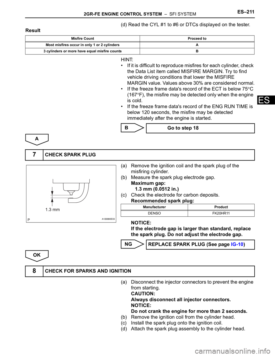
(d) Read the CYL #1 to #6 or DTCs displayed on the tester.
Result
HINT:
• If it is difficult to reproduce misfires for each cylinder, check
the Data List item called MISFIRE MARGIN. Try to find
vehicle driving conditions that lower the MISFIRE
MARGIN value. Values above 30% are considered normal.
• If the freeze frame data's record of the ECT is below 75
C
(167
F), the misfire may be detected only when the engine
is cold.
• If the freeze frame data's record of the ENG RUN TIME is
below 120 seconds, the misfire may be detected
immediately after the engine is started.
B
A
(a) Remove the ignition coil and the spark plug of the
misfiring cylinder.
(b) Measure the spark plug electrode gap.
Maximum gap:
1.3 mm (0.0512 in.)
(c) Check the electrode for carbon deposits.
Recommended spark plug:
NOTICE:
If the electrode gap is larger than standard, replace
the spark plug. Do not adjust the electrode gap.
NG
OK
(a) Disconnect the injector connectors to prevent the engine
from starting.
CAUTION:
Always disconnect all injector connectors.
NOTICE:
Do not crank the engine for more than 2 seconds.
(b) Remove the ignition coil from the cylinder head.
(c) Install the spark plug onto the ignition coil.
(d) Attach the spark plug assembly to the cylinder head.
Misfire Count Proceed to
Most misfires occur in only 1 or 2 cylinders A
3 cylinders or more have equal misfire counts B
Go to step 18
7CHECK SPARK PLUG
A126880E03
Manufacturer Product
DENSO FK20HR11
REPLACE SPARK PLUG (See page IG-10)
8CHECK FOR SPARKS AND IGNITION
Page 518 of 3000
ES–2122GR-FE ENGINE CONTROL SYSTEM – SFI SYSTEM
ES
(e) Crank the engine for less than 2 seconds and check the
spark.
OK:
Sparks jump across electrode gap.
(f) Install the ignition coil.
(g) Reconnect the injector connectors.
NG
OK
(a) Measure the cylinder compression pressure of the
misfiring cylinder (See page EM-3).
NG
OK
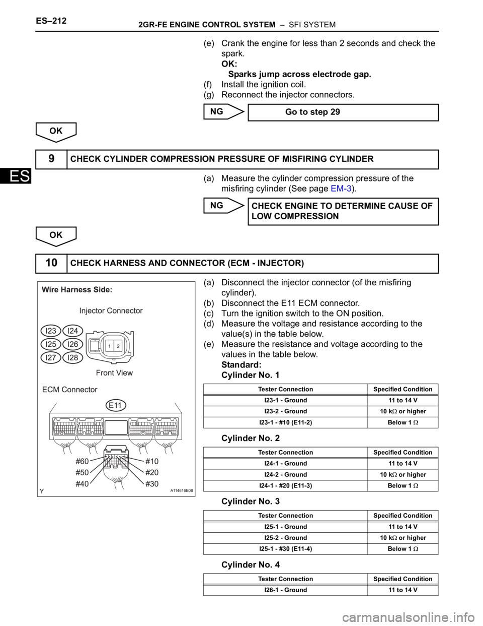
(a) Disconnect the injector connector (of the misfiring
cylinder).
(b) Disconnect the E11 ECM connector.
(c) Turn the ignition switch to the ON position.
(d) Measure the voltage and resistance according to the
value(s) in the table below.
(e) Measure the resistance and voltage according to the
values in the table below.
Standard:
Cylinder No. 1
Cylinder No. 2
Cylinder No. 3
Cylinder No. 4 Go to step 29
9CHECK CYLINDER COMPRESSION PRESSURE OF MISFIRING CYLINDER
CHECK ENGINE TO DETERMINE CAUSE OF
LOW COMPRESSION
10CHECK HARNESS AND CONNECTOR (ECM - INJECTOR)
A114616E08
Tester Connection Specified Condition
I23-1 - Ground 11 to 14 V
I23-2 - Ground 10 k
or higher
I23-1 - #10 (E11-2) Below 1
Tester Connection Specified Condition
I24-1 - Ground 11 to 14 V
I24-2 - Ground 10 k
or higher
I24-1 - #20 (E11-3) Below 1
Tester Connection Specified Condition
I25-1 - Ground 11 to 14 V
I25-2 - Ground 10 k
or higher
I25-1 - #30 (E11-4) Below 1
Tester Connection Specified Condition
I26-1 - Ground 11 to 14 V
Page 523 of 3000
2GR-FE ENGINE CONTROL SYSTEM – SFI SYSTEMES–217
ES
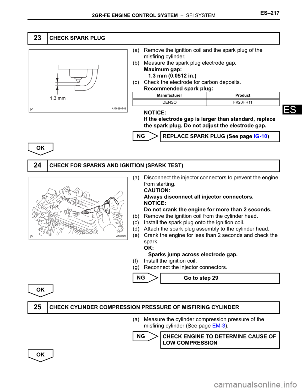
(a) Remove the ignition coil and the spark plug of the
misfiring cylinder.
(b) Measure the spark plug electrode gap.
Maximum gap:
1.3 mm (0.0512 in.)
(c) Check the electrode for carbon deposits.
Recommended spark plug:
NOTICE:
If the electrode gap is larger than standard, replace
the spark plug. Do not adjust the electrode gap.
NG
OK
(a) Disconnect the injector connectors to prevent the engine
from starting.
CAUTION:
Always disconnect all injector connectors.
NOTICE:
Do not crank the engine for more than 2 seconds.
(b) Remove the ignition coil from the cylinder head.
(c) Install the spark plug onto the ignition coil.
(d) Attach the spark plug assembly to the cylinder head.
(e) Crank the engine for less than 2 seconds and check the
spark.
OK:
Sparks jump across electrode gap.
(f) Install the ignition coil.
(g) Reconnect the injector connectors.
NG
OK
(a) Measure the cylinder compression pressure of the
misfiring cylinder (See page EM-3).
NG
OK
23CHECK SPARK PLUG
A126880E03
Manufacturer Product
DENSO FK20HR11
REPLACE SPARK PLUG (See page IG-10)
24CHECK FOR SPARKS AND IGNITION (SPARK TEST)
A136826
Go to step 29
25CHECK CYLINDER COMPRESSION PRESSURE OF MISFIRING CYLINDER
CHECK ENGINE TO DETERMINE CAUSE OF
LOW COMPRESSION
Page 525 of 3000
2GR-FE ENGINE CONTROL SYSTEM – SFI SYSTEMES–219
ES
OK
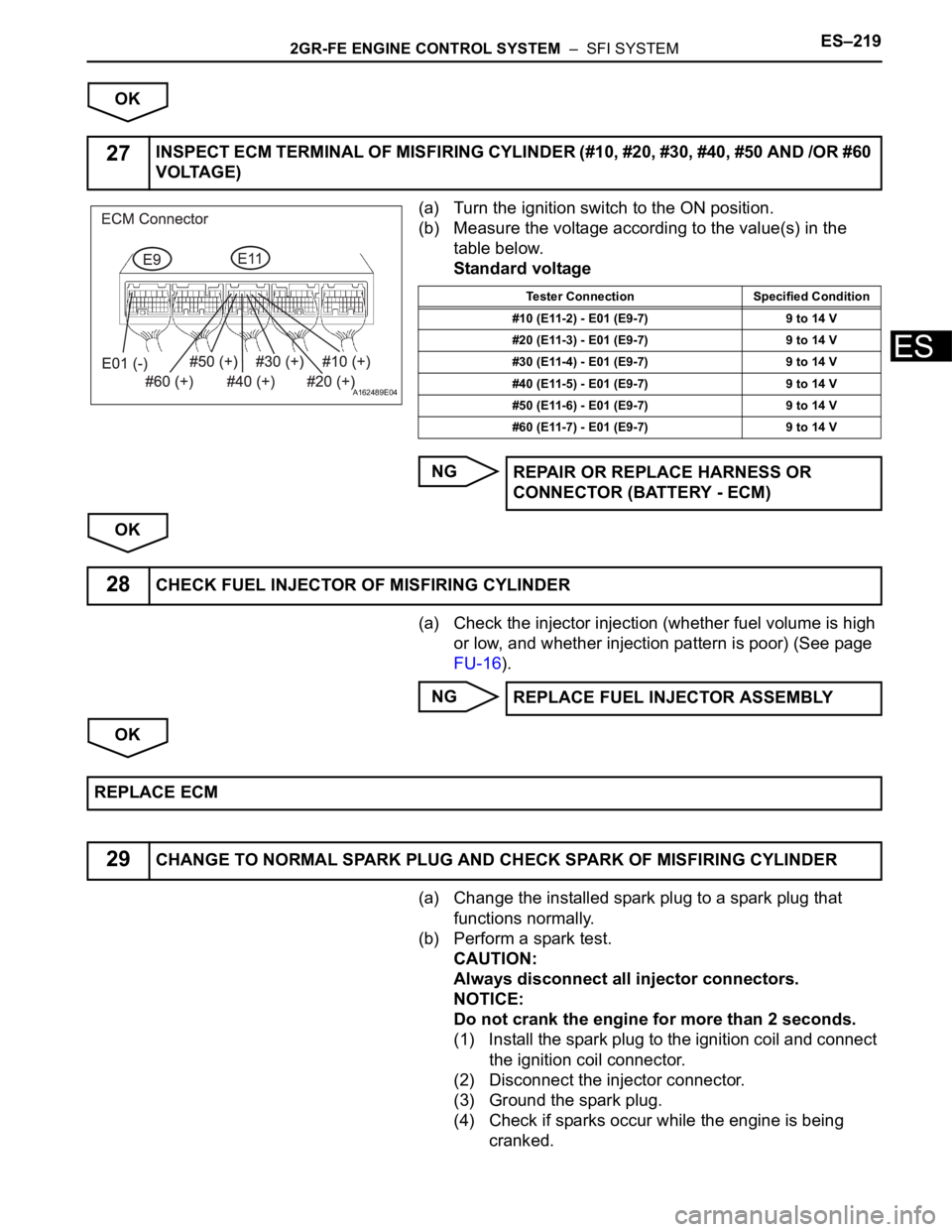
(a) Turn the ignition switch to the ON position.
(b) Measure the voltage according to the value(s) in the
table below.
Standard voltage
NG
OK
(a) Check the injector injection (whether fuel volume is high
or low, and whether injection pattern is poor) (See page
FU-16).
NG
OK
(a) Change the installed spark plug to a spark plug that
functions normally.
(b) Perform a spark test.
CAUTION:
Always disconnect all injector connectors.
NOTICE:
Do not crank the engine for more than 2 seconds.
(1) Install the spark plug to the ignition coil and connect
the ignition coil connector.
(2) Disconnect the injector connector.
(3) Ground the spark plug.
(4) Check if sparks occur while the engine is being
cranked.
27INSPECT ECM TERMINAL OF MISFIRING CYLINDER (#10, #20, #30, #40, #50 AND /OR #60
VOLTAGE)
A162489E04
Tester Connection Specified Condition
#10 (E11-2) - E01 (E9-7) 9 to 14 V
#20 (E11-3) - E01 (E9-7) 9 to 14 V
#30 (E11-4) - E01 (E9-7) 9 to 14 V
#40 (E11-5) - E01 (E9-7) 9 to 14 V
#50 (E11-6) - E01 (E9-7) 9 to 14 V
#60 (E11-7) - E01 (E9-7) 9 to 14 V
REPAIR OR REPLACE HARNESS OR
CONNECTOR (BATTERY - ECM)
28CHECK FUEL INJECTOR OF MISFIRING CYLINDER
REPLACE FUEL INJECTOR ASSEMBLY
REPLACE ECM
29CHANGE TO NORMAL SPARK PLUG AND CHECK SPARK OF MISFIRING CYLINDER
Page 526 of 3000
ES–2202GR-FE ENGINE CONTROL SYSTEM – SFI SYSTEM
ES
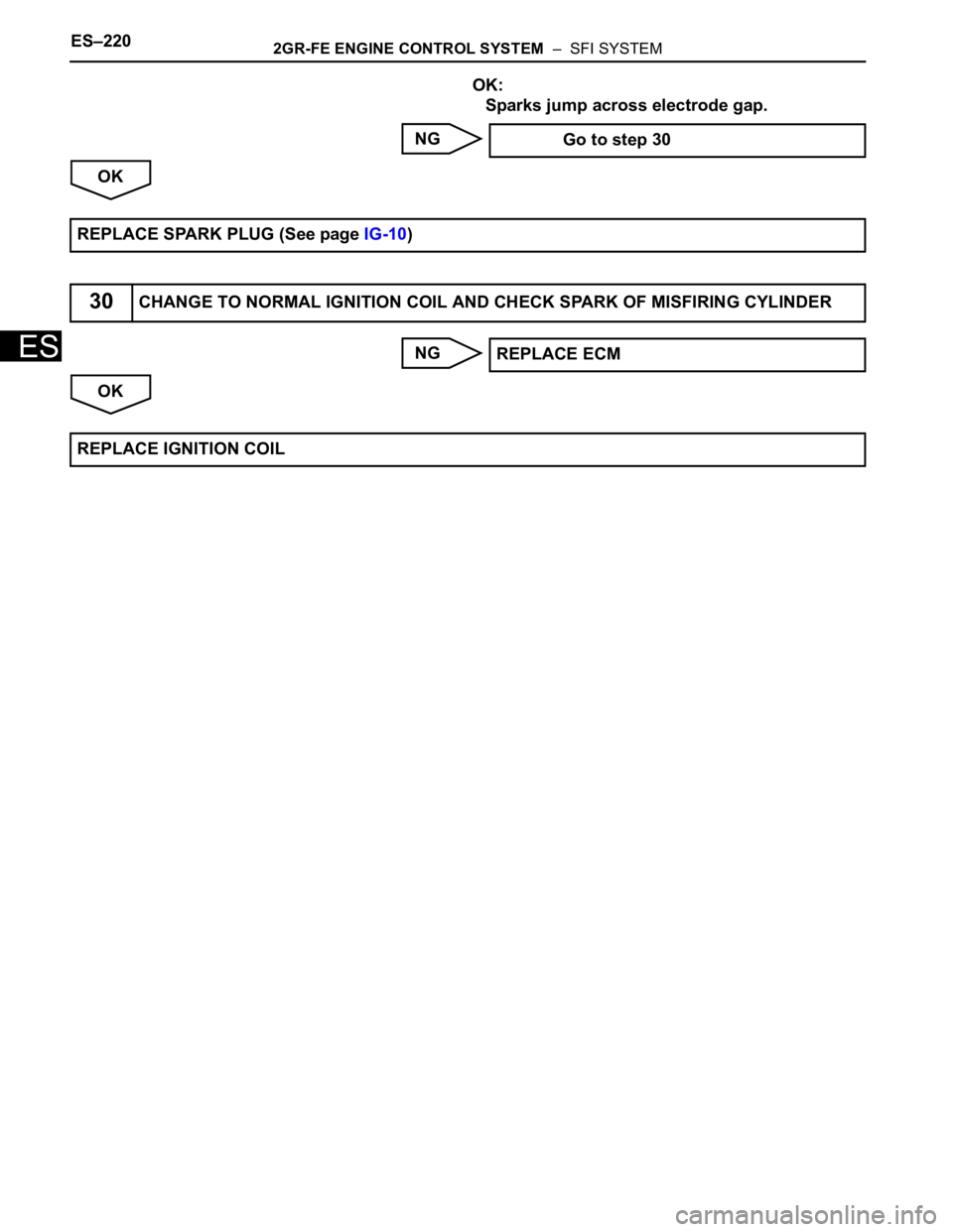
OK:
Sparks jump across electrode gap.
NG
OK
NG
OK Go to step 30
REPLACE SPARK PLUG (See page IG-10)
30CHANGE TO NORMAL IGNITION COIL AND CHECK SPARK OF MISFIRING CYLINDER
REPLACE ECM
REPLACE IGNITION COIL
Page 534 of 3000
ES–2282GR-FE ENGINE CONTROL SYSTEM – SFI SYSTEM
ES
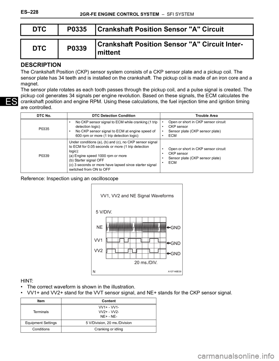
DESCRIPTION
The Crankshaft Position (CKP) sensor system consists of a CKP sensor plate and a pickup coil. The
sensor plate has 34 teeth and is installed on the crankshaft. The pickup coil is made of an iron core and a
magnet.
The sensor plate rotates as each tooth passes through the pickup coil, and a pulse signal is created. The
pickup coil generates 34 signals per engine revolution. Based on these signals, the ECM calculates the
crankshaft position and engine RPM. Using these calculations, the fuel injection time and ignition timing
are controlled.
Reference: Inspection using an oscilloscope
HINT:
• The correct waveform is shown in the illustration.
• VV1+ and VV2+ stand for the VVT sensor signal, and NE+ stands for the CKP sensor signal.
DTC P0335 Crankshaft Position Sensor "A" Circuit
DTC P0339Crankshaft Position Sensor "A" Circuit Inter-
mittent
DTC No. DTC Detection Condition Trouble Area
P0335• No CKP sensor signal to ECM while cranking (1 trip
detection logic)
• No CKP sensor signal to ECM at engine speed of
600 rpm or more (1 trip detection logic)• Open or short in CKP sensor circuit
• CKP sensor
• Sensor plate (CKP sensor plate)
•ECM
P0339Under conditions (a), (b) and (c), no CKP sensor signal
to ECM for 0.05 seconds or more (1 trip detection
logic):
(a) Engine speed 1000 rpm or more
(b) Starter signal OFF
(c) 3 seconds or more have lapsed since starter signal
switched from ON to OFF• Open or short in CKP sensor circuit
• CKP sensor
• Sensor plate (CKP sensor plate)
•ECM
Item Content
Te r m i n a l sVV1+ - VV1-
VV2+ - VV2-
NE+ - NE-
Equipment Settings 5 V/Division, 20 ms./Division
Conditions Cranking or idling
A107148E09
Page 537 of 3000
2GR-FE ENGINE CONTROL SYSTEM – SFI SYSTEMES–231
ES
INSPECTION PROCEDURE
HINT:
• If no problem is found by this diagnostic troubleshooting procedure, troubleshoot the engine
mechanical systems.
• Check the engine speed. The engine speed can be checked by using the intelligent tester. Perform the
following procedure:
(a) Connect the intelligent tester to the DLC3.
(b) Start the engine.
(c) Turn the tester on.
(d) Select the following menu items: DIAGNOSIS / ENHANCED OBD II / DATA LIST / PRIMARY /
ENGINE SPD.
The engine speed may be indicated as zero despite the engine revolving normally. This is caused
by a lack of NE signals from the Crankshaft Position (CKP) sensor. Alternatively, the engine speed
may be indicated as lower than the actual engine speed, if the CKP sensor voltage output is
insufficient.
• Read freeze frame data using the intelligent tester. The ECM records vehicle and driving condition
information as freeze frame data the moment a DTC is stored. When troubleshooting, freeze frame
data can be helpful in determining whether the vehicle was running or stopped, whether the engine
was warmed up or not, whether the air-fuel ratio was lean or rich, as well as other data recorded at the
time of a malfunction.
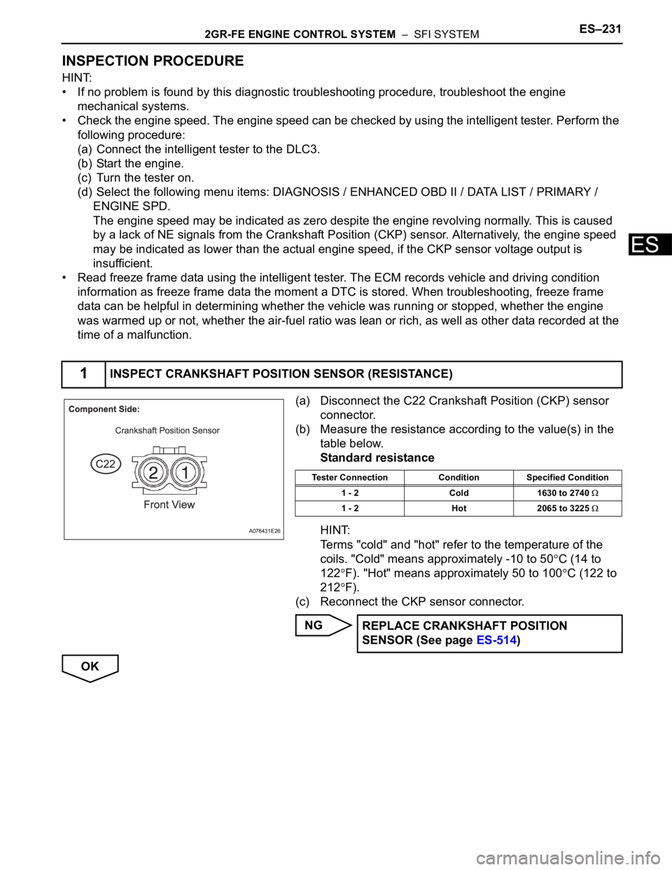
(a) Disconnect the C22 Crankshaft Position (CKP) sensor
connector.
(b) Measure the resistance according to the value(s) in the
table below.
Standard resistance
HINT:
Terms "cold" and "hot" refer to the temperature of the
coils. "Cold" means approximately -10 to 50
C (14 to
122
F). "Hot" means approximately 50 to 100C (122 to
212
F).
(c) Reconnect the CKP sensor connector.
NG
OK
1INSPECT CRANKSHAFT POSITION SENSOR (RESISTANCE)
A078431E26
Tester Connection Condition Specified Condition
1 - 2 Cold 1630 to 2740
1 - 2 Hot 2065 to 3225
REPLACE CRANKSHAFT POSITION
SENSOR (See page ES-514)
Page 540 of 3000
ES–2342GR-FE ENGINE CONTROL SYSTEM – SFI SYSTEM
ES
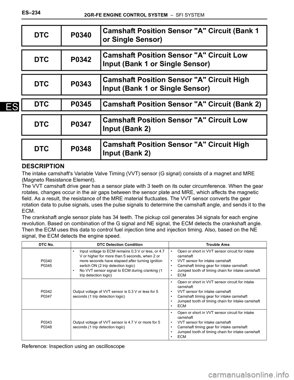
DESCRIPTION
The intake camshaft's Variable Valve Timing (VVT) sensor (G signal) consists of a magnet and MRE
(Magneto Resistance Element).
The VVT camshaft drive gear has a sensor plate with 3 teeth on its outer circumference. When the gear
rotates, changes occur in the air gaps between the sensor plate and MRE, which affects the magnetic
field. As a result, the resistance of the MRE material fluctuates. The VVT sensor converts the gear
rotation data to pulse signals, uses the pulse signals to determine the camshaft angle, and sends it to the
ECM.
The crankshaft angle sensor plate has 34 teeth. The pickup coil generates 34 signals for each engine
revolution. Based on combination of the G signal and NE signal, the ECM detects the crankshaft angle.
Then the ECM uses this data to control fuel injection time and injection timing. Also, based on the NE
signal, the ECM detects the engine speed.
Reference: Inspection using an oscilloscope
DTC P0340Camshaft Position Sensor "A" Circuit (Bank 1
or Single Sensor)
DTC P0342Camshaft Position Sensor "A" Circuit Low
Input (Bank 1 or Single Sensor)
DTC P0343Camshaft Position Sensor "A" Circuit High
Input (Bank 1 or Single Sensor)
DTC P0345 Camshaft Position Sensor "A" Circuit (Bank 2)
DTC P0347Camshaft Position Sensor "A" Circuit Low
Input (Bank 2)
DTC P0348Camshaft Position Sensor "A" Circuit High
Input (Bank 2)
DTC No. DTC Detection Condition Trouble Area
P0340
P0345• Input voltage to ECM remains 0.3 V or less, or 4.7
V or higher for more than 5 seconds, when 2 or
more seconds have elapsed after turning ignition
switch ON (2 trip detection logic)
• No VVT sensor signal to ECM during cranking (1
trip detection logic)• Open or short in VVT sensor circuit for intake
camshaft
• VVT sensor for intake camshaft
• Camshaft timing gear for intake camshaft
• Jumped tooth of timing chain for intake camshaft
•ECM
P0342
P0347Output voltage of VVT sensor is 0.3 V or less for 5
seconds (1 trip detection logic)• Open or short in VVT sensor circuit for intake
camshaft
• VVT sensor for intake camshaft
• Camshaft timing gear for intake camshaft
• Jumped tooth of timing chain for intake camshaft
•ECM
P0343
P0348Output voltage of VVT sensor is 4.7 V or more for 5
seconds (1 trip detection logic)• Open or short in VVT sensor circuit for intake
camshaft
• VVT sensor for intake camshaft
• Camshaft timing gear for intake camshaft
• Jumped tooth of timing chain for intake camshaft
•ECM
Page 547 of 3000
2GR-FE ENGINE CONTROL SYSTEM – SFI SYSTEMES–241
ES
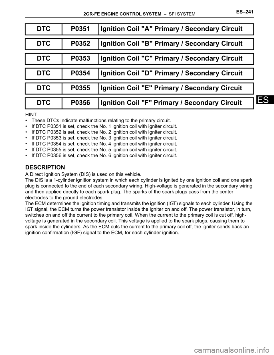
HINT:
• These DTCs indicate malfunctions relating to the primary circuit.
• If DTC P0351 is set, check the No. 1 ignition coil with igniter circuit.
• If DTC P0352 is set, check the No. 2 ignition coil with igniter circuit.
• If DTC P0353 is set, check the No. 3 ignition coil with igniter circuit.
• If DTC P0354 is set, check the No. 4 ignition coil with igniter circuit.
• If DTC P0355 is set, check the No. 5 ignition coil with igniter circuit.
• If DTC P0356 is set, check the No. 6 ignition coil with igniter circuit.
DESCRIPTION
A Direct Ignition System (DIS) is used on this vehicle.
The DIS is a 1-cylinder ignition system in which each cylinder is ignited by one ignition coil and one spark
plug is connected to the end of each secondary wiring. High-voltage is generated in the secondary wiring
and then applied directly to each spark plug. The sparks of the spark plugs pass from the center
electrodes to the ground electrodes.
The ECM determines the ignition timing and transmits the ignition (IGT) signals to each cylinder. Using the
IGT signal, the ECM turns the power transistor inside the igniter on and off. The power transistor, in turn,
switches on and off the current to the primary coil. When the current to the primary coil is cut off, high-
voltage is generated in the secondary coil. This voltage is applied to the spark plugs, causing them to
spark inside the cylinders. As the ECM cuts the current to the primary coil off, the igniter sends back an
ignition confirmation (IGF) signal to the ECM, for each cylinder ignition.
DTC P0351 Ignition Coil "A" Primary / Secondary Circuit
DTC P0352 Ignition Coil "B" Primary / Secondary Circuit
DTC P0353 Ignition Coil "C" Primary / Secondary Circuit
DTC P0354 Ignition Coil "D" Primary / Secondary Circuit
DTC P0355 Ignition Coil "E" Primary / Secondary Circuit
DTC P0356 Ignition Coil "F" Primary / Secondary Circuit