differential TOYOTA SIENNA 2007 Service Manual Online
[x] Cancel search | Manufacturer: TOYOTA, Model Year: 2007, Model line: SIENNA, Model: TOYOTA SIENNA 2007Pages: 3000, PDF Size: 52.26 MB
Page 2002 of 3000

AX–286U151F AUTOMATIC TRANSAXLE – DIFFERENTIAL CASE
AX
9. INSTALL TRANSAXLE HOUSING OIL SEAL
(a) Wind a vinyl tape around SST at the place 6.0 mm
(0.236 in.) above from the bottom end until the
thickness of the wound tape is about 5.0 mm (0.197
in.).
SST 09950-60020 (09951-00730)
NOTICE:
Remove foreign matter such as grease on the
SST before winding the tape.
(b) Coat the rip of oil seal with a little MP grease.
(c) Using SST, install a new oil seal.
SST 09950-60020 (09951-00730), 09950-70010
(09951-07150)
Standard press in depth:
5.5 - 6.5 mm (0.217 - 0.256 in.)
NOTICE:
Stop pressing when the would vinyl tape is
contact with the transaxle housing.
D003809E02
D025615E01
Page 2005 of 3000

TRANSFER – TRANSFER UNITTF–15
TF
(b) Using a plastic hammer, remove the transfer
extension housing sub- assembly from the transfer
case.
12. INSPECT PRELOAD
(a) Using SST(s) and a torque wrench, check the initial
torque with the backlash range.
SST 09326-20011
Torque: 0.9 to 1.4 N*m (9 to 14 kgf*cm, 8.0 to
12.4 in.*lbf)
HINT:
Use a torque wrench with a fulcrum length of 160
mm (6.30 in.)
(b) Using SST(s) and a torque wrench, check the initial
torque while the driven pinion is in contact with the
ring gear face.
SST 09326-20011
Torque: Preload
+ 0.15 to 0.30 N*m (+ 1.6 to 3.1 kgf*cm, +
1.3 to 2.7 in.*lbf)
HINT:
Use a torque wrench with a fulcrum length of 160
mm (6.30 in.)
13. REMOVE CTR DIFFERENTIAL LOCK SLEEVE
(a) Using snap ring pliers, remove the shaft snap ring.
(b) Using SST(s), remove the CTR differential lock
sleeve.
SST 09308-00010
C082791
C083635E01
C083637
C083638E01
Page 2006 of 3000

TF–16TRANSFER – TRANSFER UNIT
TF
14. REMOVE O-RING
(a) Using a screwdriver with the tip protected by vinyl
tape, remove the O-ring from the CTR differential
lock sleeve.
NOTICE:
Be careful not to damage the lock sleeve's
groove for the O-ring.
15. REMOVE TRANSFER CASE OIL SEAL
(a) Using SST(s), remove the transfer case oil seal
from the case.
SST 09308-00010
NOTICE:
Be careful not to damage the oil-seal-fitted
surface of the case.
16. REMOVE TRANSFER RH BEARING RETAINER OIL
SEAL
(a) Using SST(s), remove the transfer RH bearing
retainer oil seal from the transfer RH bearing
retainer sub-assembly.
SST 09308-00010
NOTICE:
Be careful not to damage the oil-seal-fitted
surface of the retainer.
17. REMOVE TRANSFER RH BEARING RETAINER SUB-
ASSEMBLY
(a) Remove the 7 bolts from the transfer RH bearing
retainer sub-assembly.
C050311
C083630E02
C082980E01
C083509
Page 2007 of 3000

TRANSFER – TRANSFER UNITTF–17
TF
(b) Using SST, make a clearance between the transfer
RH bearing retainer sub-assembly and the transfer
case.
SST 09950-00020
(c) Remove the SST.
(d) Using SST, remove the transfer RH bearing retainer
sub-assembly from the transfer case.
SST 09520-10021
18. REMOVE O-RING
(a) Using a screwdriver with the tip protected by vinyl
tape, remove the 2 O-rings from the transfer RH
bearing retainer sub-assembly.
NOTICE:
Be careful not to damage the retainer's grooves
for the O-rings.
19. REMOVE CENTER DIFFERENTIAL CASE TAPERED
ROLLER BEARING
(a) Fix the transfer RH bearing retainer sub-assembly
in a vise.
(b) Using SST(s), remove the center differential case
tapered roller bearing RH outer race, transfer ring
gear mounting case washer No. 2 and right bearing
retainer oil seal No. 2 from the transfer RH bearing
retainer sub-assembly.
SST 09308-00010
NOTICE:
Be careful not to damage the oil-seal-fitted
surface of the transfer RH bearing retainer sub-
assembly.
C149592E01
C082981E06
C050313
C083639E01
Page 2008 of 3000

TF–18TRANSFER – TRANSFER UNIT
TF
20. REMOVE SIDE GEAR SHAFT HOLDER BEARING
(a) Using snap ring pliers, remove the side gear shaft
holder hole snap ring.
(b) Remove the side gear shaft holder bearing from the
transfer RH bearing retainer sub-assembly.
21. REMOVE TRANSFER RING GEAR MOUNTING CASE
(a) Remove the transfer ring gear mounting case from
the transfer case.
22. REMOVE CENTER DIFFERENTIAL CASE TAPERED
ROLLER BEARING
(a) Using SST(s), remove the inner race of the center
differential case tapered roller bearing from the
transfer ring gear mounting case.
NOTICE:
Apply grease to the screw thread and tip of the
SST(s) before use.
(b) When the roller comes off due to deformation of the
gauge, completely remove the roller and remaining
inner races of the center differential case tapered
roller bearing from the transfer ring gear mounting
case.
NOTICE:
Apply grease to the screw thread and tip of the
SST(s) before use.
(c) Using SST(s), remove the inner race of the center
differential case tapered roller bearing from the
transfer ring gear mounting case.
NOTICE:
Apply grease to the screw thread and tip of the
SST(s) before use.
C083640
C067673
C083641E01
C083642E01
C083643E01
Page 2009 of 3000

TRANSFER – TRANSFER UNITTF–19
TF
(d) When the roller comes off due to deformation of the
gauge, completely remove the roller and remaining
inner races of the center differential case tapered
roller bearing from the transfer ring gear mounting
case.
NOTICE:
Apply grease to the screw thread and tip of the
SST(s) before use.
23. REMOVE RING GEAR
(a) Put matchmarks on the transfer ring gear mounting
case and the ring gear.
(b) Remove the 12 bolts.
(c) Using a plastic hammer, remove the ring gear by
tapping around its periphery.
NOTICE:
Do not damage the teeth of the ring gear.
24. REMOVE TRANSFER GEAR NUT
(a) Using SST(s) and a hammer, unstake the transfer
gear nut.
SST 09930-00010
(b) Using SST(s), remove the transfer gear nut.
C083644E01
C083645E01
C067677
C082795E01
C082984E01
Page 2010 of 3000

TF–20TRANSFER – TRANSFER UNIT
TF
(c) Using a press, remove the driven pinion, transfer
driven pinion rear bearing inner race and transfer
pinion bearing spacer.
NOTICE:
• Put shop cloths around to help prevent the
driven pinion from bearing dropped.
• Place something like wood blocks under the
case to keep it level.
25. REMOVE TRANSFER DRIVEN PINION FRONT
BEARING
(a) Using SST(s) and a press, remove the transfer
driven pinion front bearing inner race from the
driven pinion.
SST 09950-00020
26. REMOVE CENTER DIFFERENTIAL CASE TAPERED
ROLLER BEARING
(a) Using a brass bar and a hammer, lightly strike the
center differential case tapered roller bearing LH
outer race at 2 positions to remove it from the
transfer case.
27. REMOVE TRANSFER OUTPUT WASHER
(a) Remove the ring gear mounting case plate washer
from the transfer case.
28. REMOVE CENTER DIFFERENTIAL CASE TAPERED
ROLLER BEARING
(a) Using brass bar and a hammer, lightly strike the
transfer driven pinion front bearing outer race at 2
points to remove it from the transfer case.
29. REMOVE RING GEAR MOUNTING CASE PLATE
WA S HE R
(a) Remove the transfer output washer from the
transfer case.
30. REMOVE TRANSFER DRIVEN PINION REAR
BEARING
(a) Using a brass bar and a hammer, lightly strike the
transfer driven pinion rear bearing outer race at 2
points to remove it from the transfer case.
C082796
C083646E01
C050329
C082781
C050331
Page 2011 of 3000

TRANSFER – TRANSFER UNITTF–21
TF
INSPECTION
1. INSPECT PRELOAD
(a) Using SST(s) and a torque wrench, check the initial
torque within the backlash range.
SST 09326-20011
Torque: 0.9 to 1.4 N*m (9 to 14 kgf*cm, 8.0 to
12.4 in.*lbf)
HINT:
Use a torque wrench with a fulcrum length of 160
mm (6.30 in.).
(b) Using SST(s) and a torque wrench, check the initial
torque while the driven pinion is in contact with the
ring gear face.
SST 09326-20011
Torque: Preload
+0.15 to 0.30 N*m (+1.6 to 3.1 kgf*cm,
+1.3 to 2.7 in.*lbf)
HINT:
Use a torque wrench with a fulcrum length of 160
mm (6.30 in.).
2. INSPECT DIFFERENTIAL RING GEAR BACKLASH
(a) Set the dial gauge perpendicular to the tooth face of
the ring gear, fix the driven pinion and inspect the
backlash while moving the gear.
Backlash:
0.10 to 0.15 mm (0.0039 to 0.0059 in.)
NOTICE:
Inspect it at 3 points or more on the gear's
periphery.
3. INSPECT TOOTH CONTACT BETWEEN RING GEAR
AND DRIVE PINION
(a) Apply red lead primer thinly and uniformly to both
faces of the ring gear and rotate several times.
NOTICE:
Inspect the tooth contact on the ring gear at 4
places or more.
4. INSPECT RUNOUT OF TRANSFER RING GEAR
MOUNTING CASE
(a) Using a dial gauge check the transfer ring gear
mounting case runout.
Maximum runout:
0.03 mm (0.0012 in.)
C083635E05
C050309
C050346
C099000
Page 2012 of 3000

TF–22TRANSFER – TRANSFER UNIT
TF
REASSEMBLY
1. INSTALL TRANSFER DRIVEN PINION REAR
BEARING
(a) Using SST(s) and a press, install the transfer driven
pinion rear bearing outer race to the transfer case.
SST 09950-60010 (09951-00620), 09950-70010
(09951-07150)
NOTICE:
Place something like wood blocks under the
case to keep its level.
2. INSTALL TRANSFER OUTPUT WASHER
(a) Install the transfer output washer to the transfer
case.
HINT:
Reuse the washer.
3. INSTALL TRANSFER DRIVEN PINION FRONT
BEARING
(a) Install the transfer driven pinion front bearing outer
race to the transfer case with SST(s), bolt and nut.
SST 09950-60020 (09951-00750, 09951-00770,
09951-00810), 09316-60011 (09316-00061)
4. INSTALL RING GEAR MOUNTING CASE PLATE
WA S HE R
(a) Install the ring gear mounting case plate washer to
the transfer case.
HINT:
Reuse the washer.
5. INSTALL CENTER DIFFERENTIAL CASE TAPERED
ROLLER BEARING
(a) Using SST(s) and a press, install the center
differential case tapered roller bearing LH outer race
to the transfer case.
SST 09950-70010 (09951-07200), 09316-60011
(09316-00021)
6. INSTALL TRANSFER DRIVEN PINION FRONT
BEARING
(a) Using SST(s) and a press, install the transfer driven
pinion front bearing inner race to the driven pinion.
C082982E01
C083647E01
C083648E01
C083649E01
Page 2014 of 3000
TF–24TRANSFER – TRANSFER UNIT
TF
(d) If the preload is insufficient, even though the
tightening torque of the transfer gear nut exceeds
the maximum of the standard value., loosen the
transfer gear nut and apply gear oil SAE 90 (GL-5)
to the transfer gear nut and the screw thread and
the base of driven pinion. And then repeat the
preceding operation . If the tightening torque is
bearing spacer with anew one and adjust it.
Torque: 378 N*m (3.855 kgf*cm, 279 ft.*lbf)
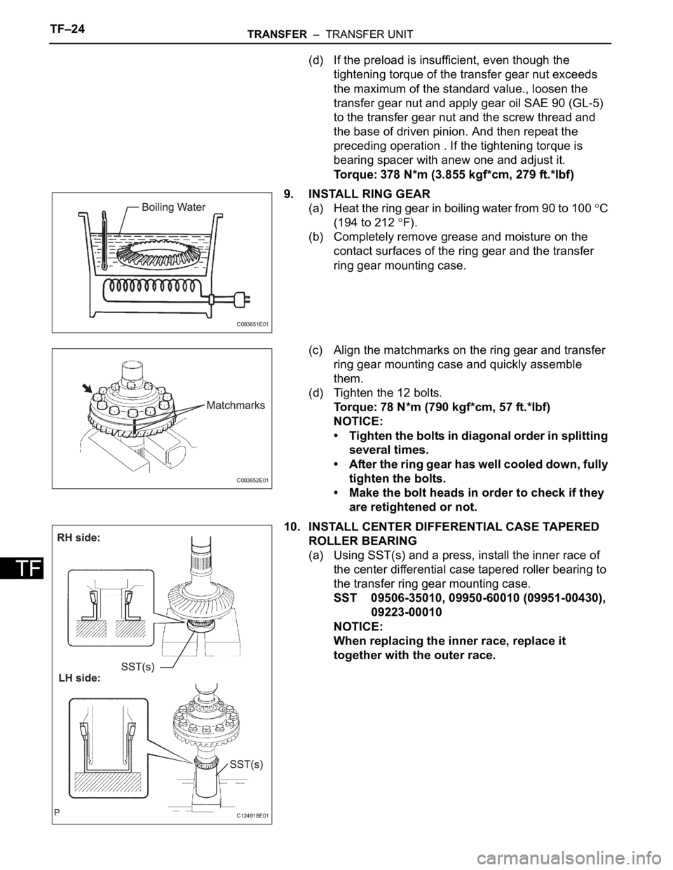
9. INSTALL RING GEAR
(a) Heat the ring gear in boiling water from 90 to 100
C
(194 to 212
F).
(b) Completely remove grease and moisture on the
contact surfaces of the ring gear and the transfer
ring gear mounting case.
(c) Align the matchmarks on the ring gear and transfer
ring gear mounting case and quickly assemble
them.
(d) Tighten the 12 bolts.
Torque: 78 N*m (790 kgf*cm, 57 ft.*lbf)
NOTICE:
• Tighten the bolts in diagonal order in splitting
several times.
• After the ring gear has well cooled down, fully
tighten the bolts.
• Make the bolt heads in order to check if they
are retightened or not.
10. INSTALL CENTER DIFFERENTIAL CASE TAPERED
ROLLER BEARING
(a) Using SST(s) and a press, install the inner race of
the center differential case tapered roller bearing to
the transfer ring gear mounting case.
SST 09506-35010, 09950-60010 (09951-00430),
09223-00010
NOTICE:
When replacing the inner race, replace it
together with the outer race.
C083651E01
C083652E01
C124918E01