VAUXHALL COMBO 2014 Owner's Manual
Manufacturer: VAUXHALL, Model Year: 2014, Model line: COMBO, Model: VAUXHALL COMBO 2014Pages: 187, PDF Size: 4.15 MB
Page 131 of 187

Vehicle care129
If the cooling system is cold, the
coolant level should be between the
MIN and MAX mark. Top up if the
level is low.
9 Warning
Allow the engine to cool before
opening the cap. Carefully open
the cap, relieving the pressure
slowly.
To top up use a 1:1 mixture of
released coolant concentrate mixed
with clean tap water. If no coolant
concentrate is available, use clean
tap water. Install the cap tightly. Have
the coolant concentration checked
and have the cause of the coolant
loss remedied by a workshop.
Power steering fluid
If the fluid level in the reservoir falls
below the MIN mark consult a
workshop.
Washer fluid
Fill with clean water mixed with a
suitable quantity of windscreen
washer fluid which contains
antifreeze.
Caution
Only washer fluid with a sufficient
antifreeze concentration provides
protection at low temperatures or
a sudden drop in temperature.
Page 132 of 187

130Vehicle careBrakesA squealing noise, or illumination ofbrake pad wear control indicator F
indicates that the brake lining is at its
minimum thickness.
Continued driving is possible but
have the brake linings replaced as
soon as possible.
Once new brake linings are installed,
do not brake unnecessarily hard for
the first few journeys.
Brake pad wear indicator F 3 75.
Brake fluid9 Warning
Brake fluid is poisonous and
corrosive. Avoid contact with eyes, skin, fabrics and painted surfaces.
The brake fluid level must be betweenthe MIN and MAX marks.
When topping up, ensure maximum cleanliness as contamination of the
brake fluid can lead to brake system
malfunctions. Have the cause of the
loss of brake fluid remedied by a
workshop.
Only use high-performance brake
fluid approved for the vehicle.
Brake and clutch fluid 3 159.
Battery
The vehicle battery is maintenance-
free provided that the driving profile
allows sufficient charging of the
battery. Short-distance-driving and
frequent engine starts can discharge
the battery. Avoid the use of
unnecessary electrical consumers.
Batteries do not belong in household
waste. They must be disposed of at
an appropriate recycling collection
point.
Laying up the vehicle for more than
4 weeks can lead to battery
discharge. Disconnect the clamp from the negative terminal of the vehicle
battery.
Ensure the ignition is switched off
before connecting or disconnecting
the vehicle battery.
Page 133 of 187
Vehicle care131
The anti-theft alarm siren must be
deactivated as follows: Switch the ignition on then off, disconnect the
vehicle's battery within 15 seconds.
Replacing the battery Notice
Any deviation from the instructions
given in this paragraph may lead to
a temporary deactivation of the stop-
start system.
In vehicles with stop-start system,
ensure the correct battery is used
when replacing the battery. We
recommend that you have the battery
replaced by a workshop.
Stop-start system 3 103.
Charging the battery9 Warning
On vehicles with stop-start
system, ensure that the charging potential does not exceed 14.6
volts when using a battery
charger. Otherwise the battery
might be damaged.
Jump starting 3 152.
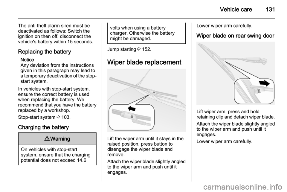
Wiper blade replacement
Lift the wiper arm until it stays in the
raised position, press button to
disengage the wiper blade and
remove.
Attach the wiper blade slightly angled
to the wiper arm and push until it
engages.
Lower wiper arm carefully.
Wiper blade on rear swing door
Lift wiper arm, press and hold
retaining clip and detach wiper blade.
Attach the wiper blade slightly angled
to the wiper arm and push until it
engages.
Lower wiper arm carefully.
Page 134 of 187
132Vehicle care
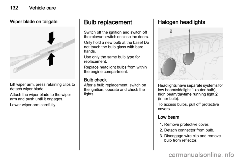
Wiper blade on tailgate
Lift wiper arm, press retaining clips to
detach wiper blade.
Attach the wiper blade to the wiper
arm and push until it engages.
Lower wiper arm carefully.
Bulb replacement
Switch off the ignition and switch off
the relevant switch or close the doors.
Only hold a new bulb at the base! Do not touch the bulb glass with bare
hands.
Use only the same bulb type for
replacement.
Replace headlight bulbs from within
the engine compartment.
Bulb check After a bulb replacement, switch on
the ignition, operate and check the
lights.Halogen headlights
Headlights have separate systems for low beam/sidelight 1 (outer bulb),
high beam/daytime running light 2
(inner bulb).
To access bulbs, pull off protective
covers.
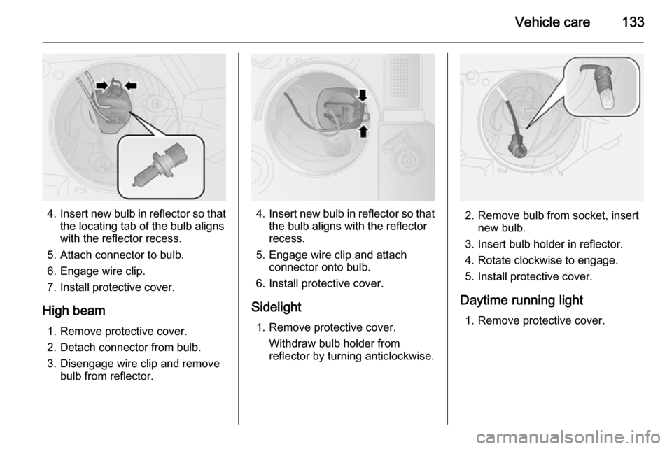
Low beam 1. Remove protective cover.
2. Detach connector from bulb.
3. Disengage wire clip and remove bulb from reflector.
Page 135 of 187
Vehicle care133
4.Insert new bulb in reflector so that
the locating tab of the bulb aligns
with the reflector recess.
5. Attach connector to bulb.
6. Engage wire clip.
7. Install protective cover.
High beam 1. Remove protective cover.
2. Detach connector from bulb.
3. Disengage wire clip and remove bulb from reflector.4.Insert new bulb in reflector so that
the bulb aligns with the reflector
recess.
5. Engage wire clip and attach connector onto bulb.
6. Install protective cover.
Sidelight 1. Remove protective cover. Withdraw bulb holder from
reflector by turning anticlockwise.2. Remove bulb from socket, insert new bulb.
3. Insert bulb holder in reflector. 4. Rotate clockwise to engage.
5. Install protective cover.
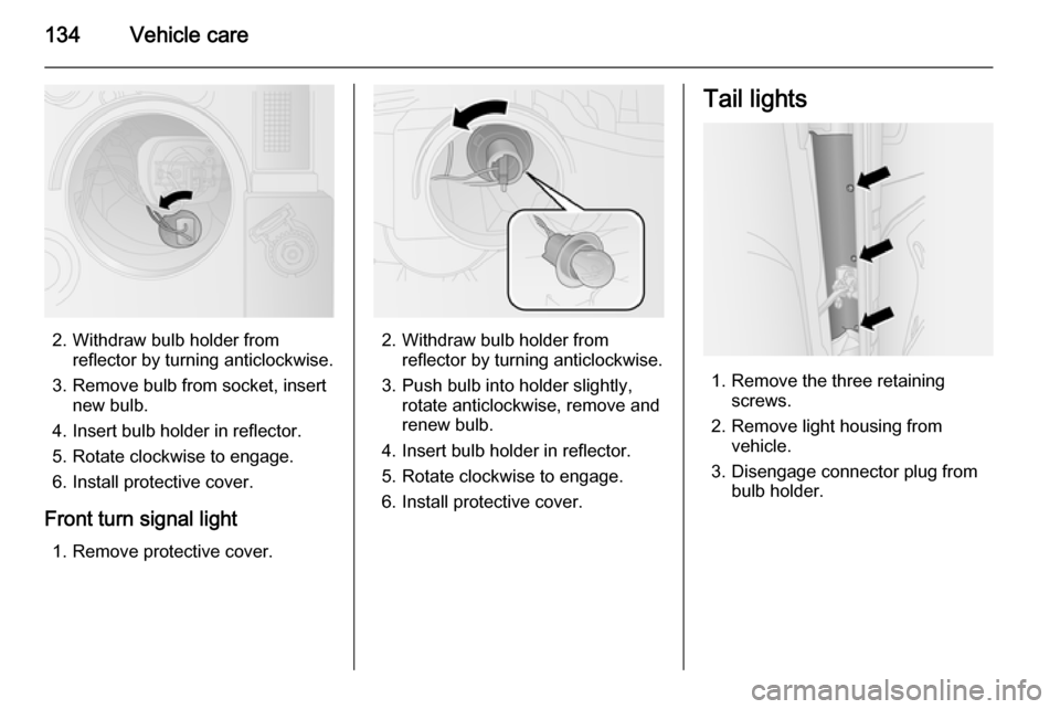
Daytime running light 1. Remove protective cover.
Page 136 of 187
134Vehicle care
2. Withdraw bulb holder fromreflector by turning anticlockwise.
3. Remove bulb from socket, insert new bulb.
4. Insert bulb holder in reflector. 5. Rotate clockwise to engage.
6. Install protective cover.
Front turn signal light 1. Remove protective cover.2. Withdraw bulb holder from reflector by turning anticlockwise.
3. Push bulb into holder slightly, rotate anticlockwise, remove and
renew bulb.
4. Insert bulb holder in reflector.
5. Rotate clockwise to engage.
6. Install protective cover.
Tail lights
1. Remove the three retaining screws.
2. Remove light housing from vehicle.
3. Disengage connector plug from bulb holder.
Page 137 of 187
Vehicle care135
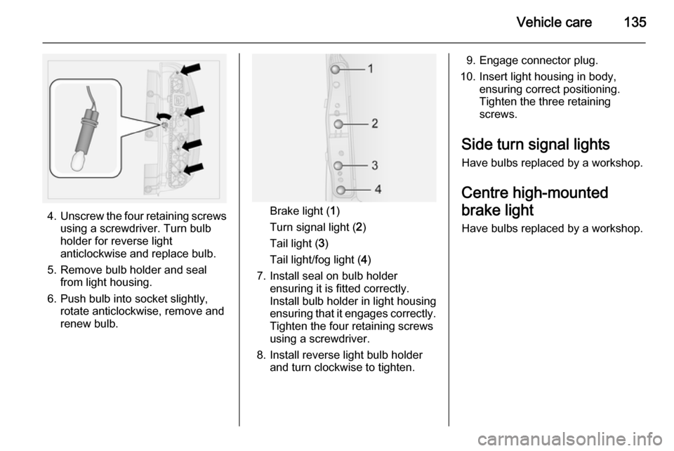
4.Unscrew the four retaining screws
using a screwdriver. Turn bulb
holder for reverse light
anticlockwise and replace bulb.
5. Remove bulb holder and seal from light housing.
6. Push bulb into socket slightly, rotate anticlockwise, remove and
renew bulb.Brake light ( 1)
Turn signal light ( 2)
Tail light ( 3)
Tail light/fog light ( 4)
7. Install seal on bulb holder ensuring it is fitted correctly.
Install bulb holder in light housing
ensuring that it engages correctly.
Tighten the four retaining screws
using a screwdriver.
8. Install reverse light bulb holder and turn clockwise to tighten.
9. Engage connector plug.
10. Insert light housing in body, ensuring correct positioning.
Tighten the three retaining
screws.
Side turn signal lights
Have bulbs replaced by a workshop.
Centre high-mounted
brake light Have bulbs replaced by a workshop.
Page 138 of 187
136Vehicle careNumber plate lightTailgate
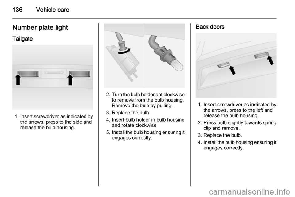
1. Insert screwdriver as indicated by
the arrows, press to the side and
release the bulb housing.
2. Turn the bulb holder anticlockwise
to remove from the bulb housing.
Remove the bulb by pulling.
3. Replace the bulb.
4. Insert bulb holder in bulb housing and rotate clockwise
5. Install the bulb housing ensuring it
engages correctly.
Back doors
1. Insert screwdriver as indicated by
the arrows, press to the left and
release the bulb housing.
2. Press bulb slightly towards spring
clip and remove.
3. Replace the bulb.
4. Install the bulb housing ensuring it
engages correctly.
Page 139 of 187
Vehicle care137Interior lightsFront and rear courtesy light
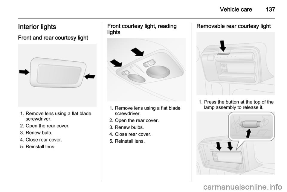
1. Remove lens using a flat blade screwdriver.
2. Open the rear cover. 3. Renew bulb.
4. Close rear cover.
5. Reinstall lens.
Front courtesy light, reading
lights
1. Remove lens using a flat blade screwdriver.
2. Open the rear cover. 3. Renew bulbs.
4. Close rear cover.
5. Reinstall lens.
Removable rear courtesy light
1. Press the button at the top of the lamp assembly to release it.
Page 140 of 187
138Vehicle care
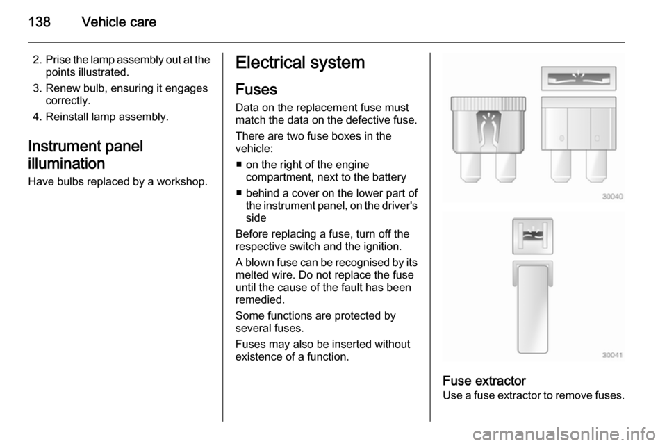
2.Prise the lamp assembly out at the
points illustrated.
3. Renew bulb, ensuring it engages correctly.
4. Reinstall lamp assembly.
Instrument panel
illumination Have bulbs replaced by a workshop.Electrical system
Fuses
Data on the replacement fuse must
match the data on the defective fuse.
There are two fuse boxes in the
vehicle:
■ on the right of the engine compartment, next to the battery
■ behind a cover on the lower part of the instrument panel, on the driver'sside
Before replacing a fuse, turn off the
respective switch and the ignition.
A blown fuse can be recognised by its
melted wire. Do not replace the fuse
until the cause of the fault has been
remedied.
Some functions are protected by
several fuses.
Fuses may also be inserted without existence of a function.
Fuse extractor
Use a fuse extractor to remove fuses.