ECU VOLKSWAGEN CORRADO 1990 Service Manual
[x] Cancel search | Manufacturer: VOLKSWAGEN, Model Year: 1990, Model line: CORRADO, Model: VOLKSWAGEN CORRADO 1990Pages: 906, PDF Size: 6.56 MB
Page 592 of 906
I - SYSTEM/COMPONENT TESTS
Article Text (p. 5)
1990 Volkswagen Corrado
For Volkswagen Technical Site: http://vw.belcom.ru
Copyright © 1998 Mitchell Repair Information Company, LLC
Thursday, March 23, 2000 09:46PM
COOLANT TEMPERATURE SENSOR
Turn ignition off. Use a thermometer to measure coolant
temperature. Unplug connector from Electronic Control Unit (ECU).
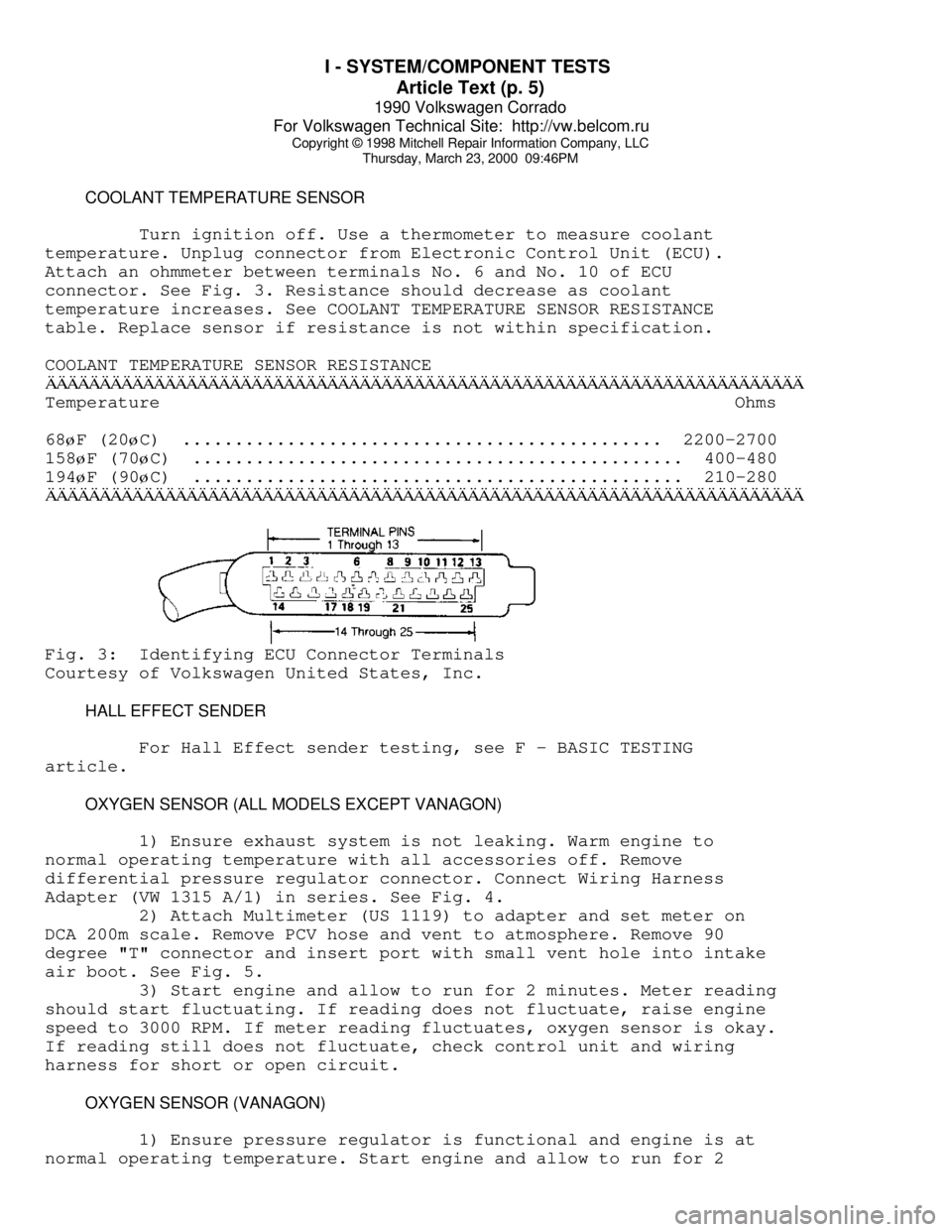
Attach an ohmmeter between terminals No. 6 and No. 10 of ECU
connector. See Fig. 3. Resistance should decrease as coolant
temperature increases. See COOLANT TEMPERATURE SENSOR RESISTANCE
table. Replace sensor if resistance is not within specification.
COOLANT TEMPERATURE SENSOR RESISTANCEÄÄÄÄÄÄÄÄÄÄÄÄÄÄÄÄÄÄÄÄÄÄÄÄÄÄÄÄÄÄÄÄÄÄÄÄÄÄÄÄÄÄÄÄÄÄÄÄÄÄÄÄÄÄÄÄÄÄÄÄÄÄÄÄÄÄÄÄÄÄTemperature Ohms
68
øF (20øC) .............................................. 2200-2700
158
øF (70øC) ............................................... 400-480
194
øF (90øC) ............................................... 210-280
ÄÄÄÄÄÄÄÄÄÄÄÄÄÄÄÄÄÄÄÄÄÄÄÄÄÄÄÄÄÄÄÄÄÄÄÄÄÄÄÄÄÄÄÄÄÄÄÄÄÄÄÄÄÄÄÄÄÄÄÄÄÄÄÄÄÄÄÄÄÄFig. 3: Identifying ECU Connector Terminals
Courtesy of Volkswagen United States, Inc.
HALL EFFECT SENDER
For Hall Effect sender testing, see F - BASIC TESTING
article.
OXYGEN SENSOR (ALL MODELS EXCEPT VANAGON)
1) Ensure exhaust system is not leaking. Warm engine to
normal operating temperature with all accessories off. Remove
differential pressure regulator connector. Connect Wiring Harness
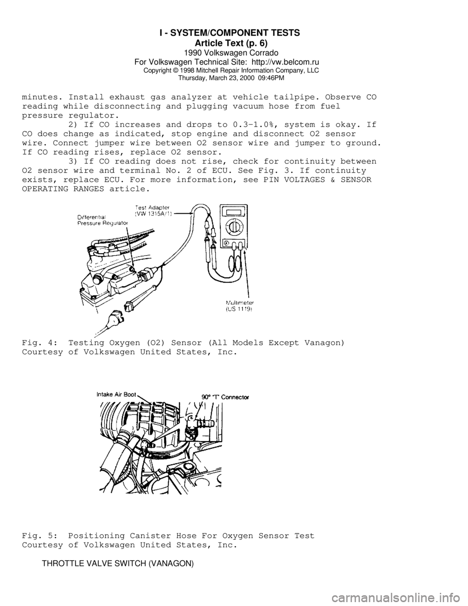
Adapter (VW 1315 A/1) in series. See Fig. 4.
2) Attach Multimeter (US 1119) to adapter and set meter on
DCA 200m scale. Remove PCV hose and vent to atmosphere. Remove 90
degree "T" connector and insert port with small vent hole into intake
air boot. See Fig. 5.
3) Start engine and allow to run for 2 minutes. Meter reading
should start fluctuating. If reading does not fluctuate, raise engine
speed to 3000 RPM. If meter reading fluctuates, oxygen sensor is okay.
If reading still does not fluctuate, check control unit and wiring
harness for short or open circuit.
OXYGEN SENSOR (VANAGON)
1) Ensure pressure regulator is functional and engine is at
normal operating temperature. Start engine and allow to run for 2
Page 593 of 906
I - SYSTEM/COMPONENT TESTS
Article Text (p. 6)
1990 Volkswagen Corrado
For Volkswagen Technical Site: http://vw.belcom.ru
Copyright © 1998 Mitchell Repair Information Company, LLC
Thursday, March 23, 2000 09:46PM
minutes. Install exhaust gas analyzer at vehicle tailpipe. Observe CO
reading while disconnecting and plugging vacuum hose from fuel
pressure regulator.
2) If CO increases and drops to 0.3-1.0%, system is okay. If
CO does change as indicated, stop engine and disconnect O2 sensor
wire. Connect jumper wire between O2 sensor wire and jumper to ground.
If CO reading rises, replace O2 sensor.
3) If CO reading does not rise, check for continuity between
O2 sensor wire and terminal No. 2 of ECU. See Fig. 3. If continuity
exists, replace ECU. For more information, see PIN VOLTAGES & SENSOR
OPERATING RANGES article.Fig. 4: Testing Oxygen (O2) Sensor (All Models Except Vanagon)
Courtesy of Volkswagen United States, Inc.Fig. 5: Positioning Canister Hose For Oxygen Sensor Test
Courtesy of Volkswagen United States, Inc.
THROTTLE VALVE SWITCH (VANAGON)
Page 595 of 906

I - SYSTEM/COMPONENT TESTS
Article Text (p. 8)
1990 Volkswagen Corrado
For Volkswagen Technical Site: http://vw.belcom.ru
Copyright © 1998 Mitchell Repair Information Company, LLC
Thursday, March 23, 2000 09:46PM
FUEL PUMP RELAY (FOX)
1) Ensure fuel pump fuse (No. 13) is okay. Remove fuel pump
relay. Note terminals numbers molded on fuse/relay panel. With
ignition on, check for battery voltage between the following
locations:
* Terminal No. 46 and ground
* Terminal No. 48 and ground
2) If voltage is not present, current is not reaching the
relay. Repair wiring. Check fuel pump operation. If voltage is
present, check for battery voltage between the following locations:
* Terminals No. 48 and No. 50
* Terminals No. 46 and No. 50
If voltage is not present, terminal No. 50 (ground circuit)
is open. Repair wiring. Check fuel pump operation.
3) If voltage is present, check for battery voltage between
terminals No. 50 and No. 51. If voltage is not present, the ignition
signal is not reaching fuel pump relay. Repair wiring. Check fuel pump
operation.
4) If no faults can be found and fuel pump operates when
relay is by-passed, replace fuel pump relay. For fuel pump and fuse
number/location, see FUEL PUMP RELAY & FUSE NUMBER table.
FUEL PUMP RELAY (CORRADO)
1) Ensure fuel pump fuse No. 18 is okay. Remove fuel pump
relay No. 12 from fuse/relay panel. See Fig. 6. With ignition on,
check for battery voltage between the following locations:
* Terminal No. 6 and ground.
* Terminal No. 2 and ground.
* Terminals No. 6 and No. 4.
2) If battery voltage is not present, check wiring and repair
as needed. Check fuel pump operation. With ignition off, connect
voltmeter between terminals No. 2 and No. 3. Turn ignition on. Voltage
should be present for one second. If voltage is not present for one
second, check wiring to ECU or replace ECU. Check fuel pump relay
operation. For fuel pump and fuse number/location, see FUEL PUMP RELAY
& FUSE NUMBER table.
FUEL PUMP RELAY (VANAGON)
1) Check terminal No. 30 and terminal No. 86 of fuel pump
relay for battery voltage. If battery voltage is not present, check
circuit for short or open circuit.
2) If battery voltage is present, remove relay and attach
ohmmeter probe to relay box terminal No. 85. Attach other probe to
Page 596 of 906
I - SYSTEM/COMPONENT TESTS
Article Text (p. 9)
1990 Volkswagen Corrado
For Volkswagen Technical Site: http://vw.belcom.ru
Copyright © 1998 Mitchell Repair Information Company, LLC
Thursday, March 23, 2000 09:46PM
ground. Continuity should be present while cranking engine.
3) If continuity is not present, check for continuity between
terminal No. 85 of fuel pump relay and terminal No. 3 of ECU
connector. If continuity is present, circuit is okay but ECU is not
switching to ground. Replace ECU and install fuel pump relay.
4) If fuel pump will not operate, turn ignition switch OFF
and then ON position. Ensure battery voltage is present at fuel pump
relay No. 87 for about 5 seconds after ignition is switched on. If
battery voltage is not present, replace fuel pump relay. If battery
voltage is present, check voltage supply and ground circuit of fuel
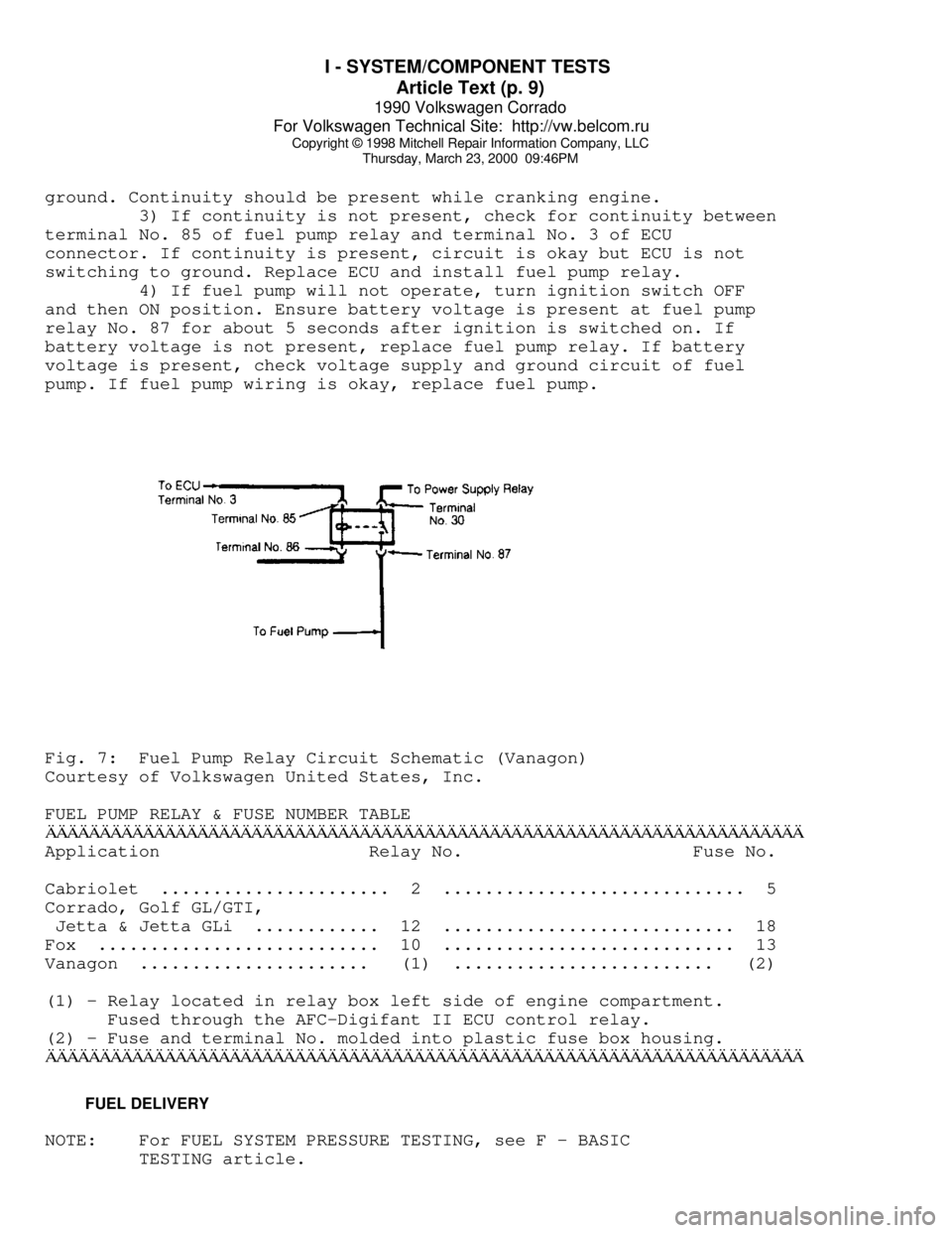
pump. If fuel pump wiring is okay, replace fuel pump.Fig. 7: Fuel Pump Relay Circuit Schematic (Vanagon)
Courtesy of Volkswagen United States, Inc.
FUEL PUMP RELAY & FUSE NUMBER TABLEÄÄÄÄÄÄÄÄÄÄÄÄÄÄÄÄÄÄÄÄÄÄÄÄÄÄÄÄÄÄÄÄÄÄÄÄÄÄÄÄÄÄÄÄÄÄÄÄÄÄÄÄÄÄÄÄÄÄÄÄÄÄÄÄÄÄÄÄÄÄApplication Relay No. Fuse No.
Cabriolet ...................... 2 ............................. 5
Corrado, Golf GL/GTI,
Jetta & Jetta GLi ............ 12 ............................ 18
Fox ........................... 10 ............................ 13
Vanagon ...................... (1) ......................... (2)
(1) - Relay located in relay box left side of engine compartment.
Fused through the AFC-Digifant II ECU control relay.
(2) - Fuse and terminal No. molded into plastic fuse box housing.
ÄÄÄÄÄÄÄÄÄÄÄÄÄÄÄÄÄÄÄÄÄÄÄÄÄÄÄÄÄÄÄÄÄÄÄÄÄÄÄÄÄÄÄÄÄÄÄÄÄÄÄÄÄÄÄÄÄÄÄÄÄÄÄÄÄÄÄÄÄÄ FUEL DELIVERY
NOTE: For FUEL SYSTEM PRESSURE TESTING, see F - BASIC
TESTING article.
Page 597 of 906
I - SYSTEM/COMPONENT TESTS
Article Text (p. 10)
1990 Volkswagen Corrado
For Volkswagen Technical Site: http://vw.belcom.ru
Copyright © 1998 Mitchell Repair Information Company, LLC
Thursday, March 23, 2000 09:46PM
FUEL CONTROL
COLD START VALVE (ALL MODELS EXCEPT VANAGON)
1) Engine temperature must be below 85øF (30øC). Disconnect
cold start valve attaching screws and remove valve with harness
connector and fuel line attached.
2) Remove ignition coil secondary wire and jumper to ground.
Attach metal housing of cold start valve to ground. Direct cold start
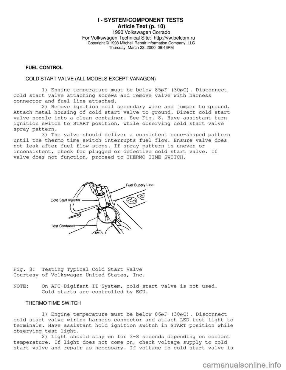
valve nozzle into a clean container. See Fig. 8. Have assistant turn
ignition switch to START position, while observing cold start valve
spray pattern.
3) The valve should deliver a consistent cone-shaped pattern
until the thermo time switch interrupts fuel flow. Ensure valve does
not leak after fuel flow stops. If spray pattern is uneven or
inconsistent, check for plugged or defective cold start valve. If
valve does not function, proceed to THERMO TIME SWITCH.Fig. 8: Testing Typical Cold Start Valve
Courtesy of Volkswagen United States, Inc.
NOTE: On AFC-Digifant II System, cold start valve is not used.
Cold starts are controlled by ECU.
THERMO TIME SWITCH
1) Engine temperature must be below 86
øF (30øC). Disconnect
cold start valve wiring harness connector and attach LED test light to
terminals. Have assistant hold ignition switch in START position while
observing test light.
2) Light should stay on for 3-8 seconds depending on coolant
temperature. If light does not come on, check voltage supply to cold
start valve and repair as necessary. If voltage to cold start valve is
Page 598 of 906

I - SYSTEM/COMPONENT TESTS
Article Text (p. 11)
1990 Volkswagen Corrado
For Volkswagen Technical Site: http://vw.belcom.ru
Copyright © 1998 Mitchell Repair Information Company, LLC
Thursday, March 23, 2000 09:46PM
okay, check ground circuit through thermo time switch. Replace thermo
time switch if contact to ground cannot be made.
IDLE CONTROL SYSTEM
NOTE: Knock control is integral in AFC-Digifant II ECU.
KNOCK SENSOR CONTROL UNIT (ALL MODELS EXCEPT VANAGON)
1) Check ignition coil and Hall Effect sender before checking
knock sensor control unit. Remove knock sensor control unit harness
connector. Turn ignition on. Using a voltmeter, check for battery
voltage between terminals No. 3 and No. 5 and terminals No. 6 and No.
3 of knock sensor control unit. Open throttle valve. Voltage should
drop to zero volts.
2) If voltage does not drop to zero volts, check throttle
valve switch (full throttle). Check voltage between terminals No. 8
and No. 3, while fully opening throttle valve. If battery voltage was
not present when throttle fully open, replace throttle valve switch.
See Fig. 13.
3) Remove Hall Effect sender connector and connect voltmeter
to outside terminals. Turn ignition on. There should be 5 volts
present. Turn ignition off. Connect voltmeter between terminals No. 1
(negative) and No. 15 (positive) of ignition coil. Turn ignition on
and touch center terminal of Hall Effect sender briefly to ground.
Voltage should jump momentarily to approximately 2 volts. If voltage
does not jump, replace knock sensor control unit.
KNOCK SENSOR(S)
Before replacing knock sensor, check knock sensor torque and
resistance. Remove knock sensor connector and check resistance between
terminals No. 13 and No. 14. See KNOCK SENSOR TORQUE & RESISTANCE
SPECIFICATION table. If resistance is incorrect, replace knock sensor.
NOTE: Knock sensor mounting bolt torque must be exact. DO NOT use
washers when mounting knock sensor.
KNOCK SENSOR RESISTANCE & TORQUE SPECIFICATIONÄÄÄÄÄÄÄÄÄÄÄÄÄÄÄÄÄÄÄÄÄÄÄÄÄÄÄÄÄÄÄÄÄÄÄÄÄÄÄÄÄÄÄÄÄÄÄÄÄÄÄÄÄÄÄÄÄÄÄÄÄÄÄÄÄÄÄÄÄÄApplication Resistance Ft. Lbs (N.m)
Type I ...................... 300,000 ................ 7-9 (10-12)
Type II .................... Infinite .............. 15-18 (20-25)
ÄÄÄÄÄÄÄÄÄÄÄÄÄÄÄÄÄÄÄÄÄÄÄÄÄÄÄÄÄÄÄÄÄÄÄÄÄÄÄÄÄÄÄÄÄÄÄÄÄÄÄÄÄÄÄÄÄÄÄÄÄÄÄÄÄÄÄÄÄÄ IDLE STABILIZATION SYSTEM (VANAGON)
1) Attach Test Meter (VW 1315/2) and Adapter (US 1119) to
idle stabilization valve. Set meter to milliampere scale. Start
engine. Observe test meter while turning A/C control switch to ON
position. If milliampere reading increases, system is okay.
Page 611 of 906
J - PIN VOLTAGE CHARTS
Article Text
1990 Volkswagen Corrado
For Volkswagen Technical Site: http://vw.belcom.ru
Copyright © 1998 Mitchell Repair Information Company, LLC
Thursday, March 23, 2000 09:46PM
ARTICLE BEGINNING
1990 ENGINE PERFORMANCE
Pin Voltage & Sensor Operating Ranges
Volkswagen; Corrado, Fox, Golf, Jetta, Vanagon
NOTE: Cabriolet pin voltage and sensor operating range charts are
not available from manufacturer.
INTRODUCTION
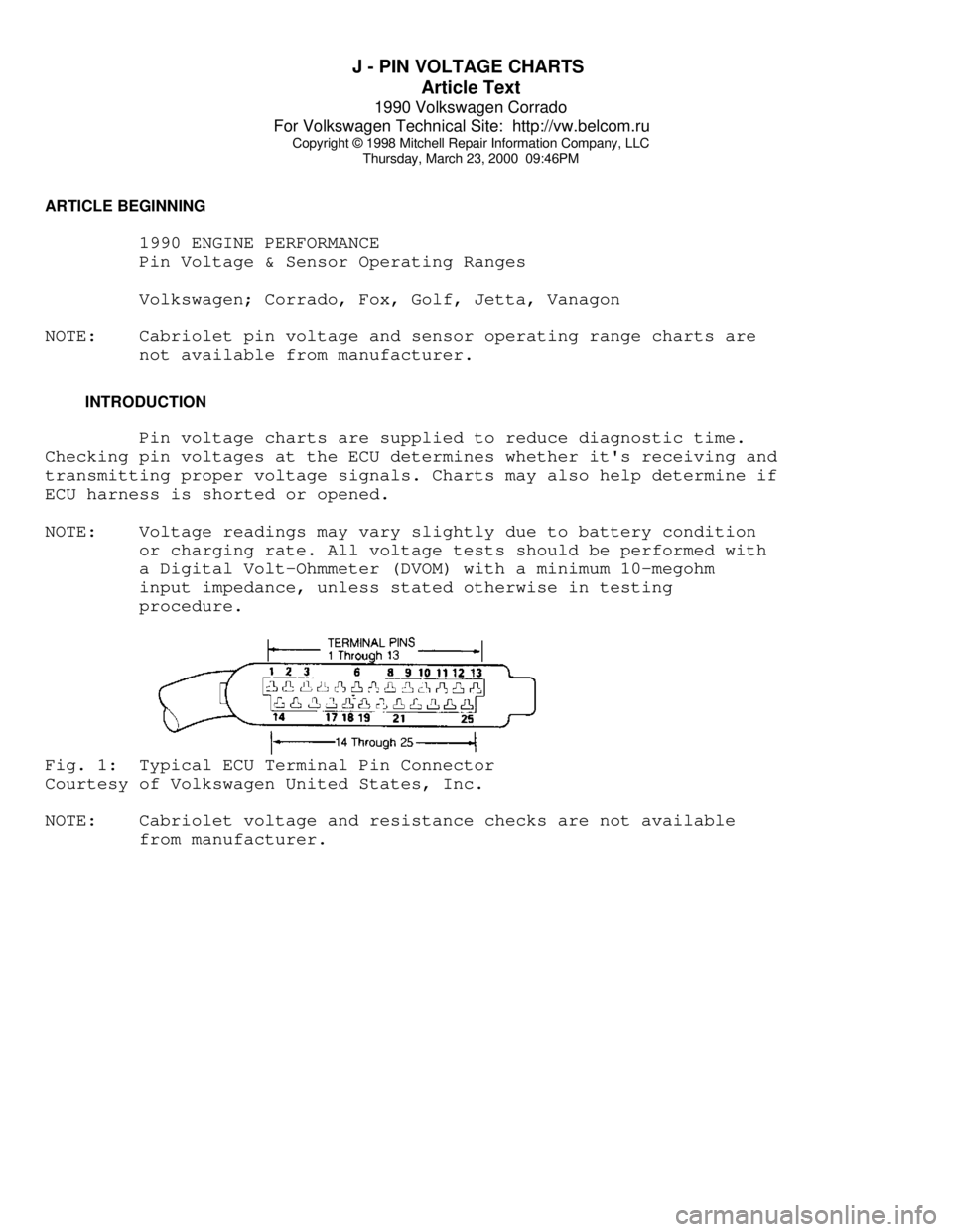
Pin voltage charts are supplied to reduce diagnostic time.
Checking pin voltages at the ECU determines whether it's receiving and
transmitting proper voltage signals. Charts may also help determine if
ECU harness is shorted or opened.
NOTE: Voltage readings may vary slightly due to battery condition
or charging rate. All voltage tests should be performed with
a Digital Volt-Ohmmeter (DVOM) with a minimum 10-megohm
input impedance, unless stated otherwise in testing
procedure.Fig. 1: Typical ECU Terminal Pin Connector
Courtesy of Volkswagen United States, Inc.
NOTE: Cabriolet voltage and resistance checks are not available
from manufacturer.
Page 612 of 906
J - PIN VOLTAGE CHARTS
Article Text (p. 2)
1990 Volkswagen Corrado
For Volkswagen Technical Site: http://vw.belcom.ru
Copyright © 1998 Mitchell Repair Information Company, LLC
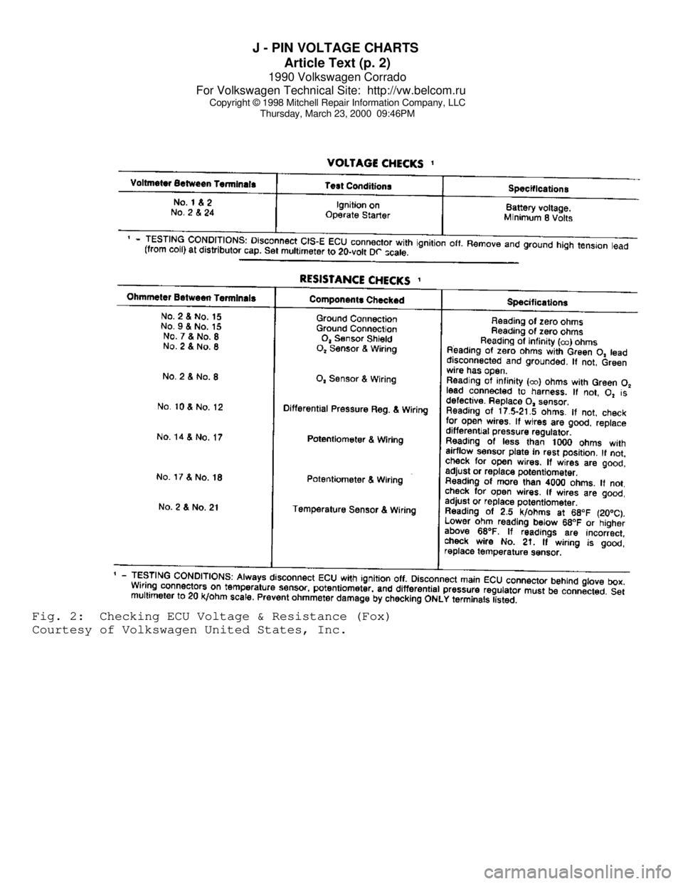
Thursday, March 23, 2000 09:46PMFig. 2: Checking ECU Voltage & Resistance (Fox)
Courtesy of Volkswagen United States, Inc.
Page 613 of 906
J - PIN VOLTAGE CHARTS
Article Text (p. 3)
1990 Volkswagen Corrado
For Volkswagen Technical Site: http://vw.belcom.ru
Copyright © 1998 Mitchell Repair Information Company, LLC
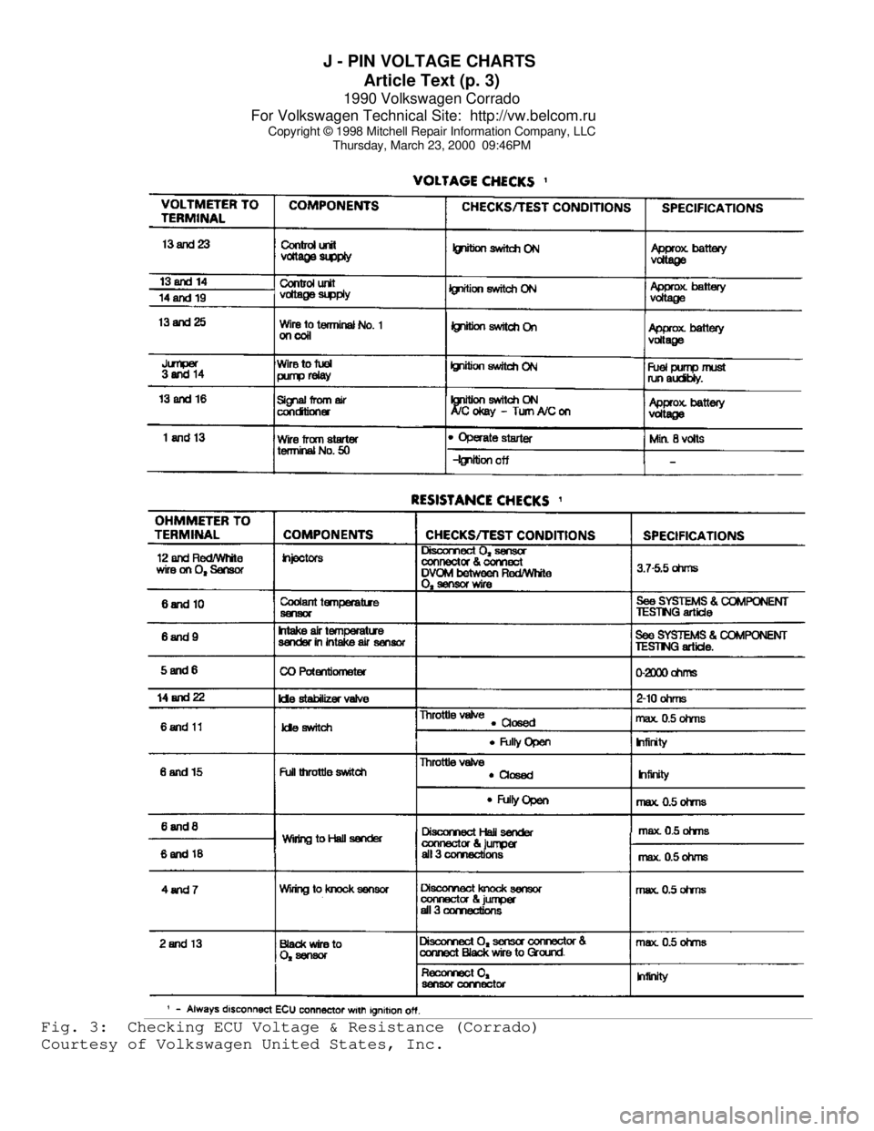
Thursday, March 23, 2000 09:46PMFig. 3: Checking ECU Voltage & Resistance (Corrado)
Courtesy of Volkswagen United States, Inc.
Page 614 of 906
J - PIN VOLTAGE CHARTS
Article Text (p. 4)
1990 Volkswagen Corrado
For Volkswagen Technical Site: http://vw.belcom.ru
Copyright © 1998 Mitchell Repair Information Company, LLC
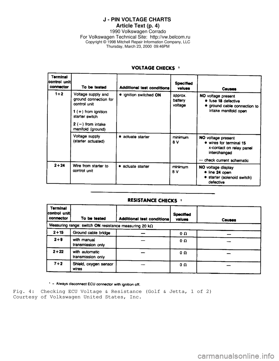
Thursday, March 23, 2000 09:46PMFig. 4: Checking ECU Voltage & Resistance (Golf & Jetta, 1 of 2)
Courtesy of Volkswagen United States, Inc.