My Car VOLVO S60 2018 Owner´s Manual
[x] Cancel search | Manufacturer: VOLVO, Model Year: 2018, Model line: S60, Model: VOLVO S60 2018Pages: 396, PDF Size: 9.4 MB
Page 48 of 396
SAFETY
46
Child safety
Children should always be seated safely when traveling in the vehicle.
General informationVolvo recommends the proper use of restraint systems (p. 47) for all occupants including chil-dren. Remember that, regardless of age and size,a child should always be properly restrained in avehicle. Your vehicle is also equipped with ISOFIX/ LATCH attachments (p. 55), which make itmore convenient to install child seats. Some restraint systems for children are designed to be secured in the vehicle by lap belts or thelap portion of a lap-shoulder belt. Such childrestraint systems can help protect children invehicles in the event of an accident only if theyare used properly. However, children could beendangered in a crash if the child restraints arenot properly secured in the vehicle. Failure to fol-low the installation instructions for your childrestraint can result in your child striking the vehi-cle's interior in a sudden stop. Holding a child in your arms is NOT a suitable substitute for a child restraint system. In an acci-dent, a child held in a person's arms can becrushed between the vehicle's interior and anunrestrained person. The child could also beinjured by striking the interior, or by being ejectedfrom the vehicle during a sudden maneuver or impact. The same can also happen if the infant orchild rides unrestrained on the seat. Other occu-pants should also be properly restrained to helpreduce the chance of injuring or increasing theinjury of a child. All states and provinces have legislation govern- ing how and where children should be carried ina vehicle. Find out the regulations existing in yourstate or province. Recent accident statistics haveshown that children are safer in rear seatingpositions than front seating positions when prop-erly restrained. A child restraint system can helpprotect a child in a vehicle. Here's what to lookfor when selecting a child restraint system: It should have a label certifying that it meets applicable Federal Motor Vehicle Safety Stand-ards (FMVSS 213) – or in Canada, CMVSS 213. Make sure the child restraint system is approved for the child's height, weight and development –the label required by the standard or regulation,or instructions for infant restraints, typically pro-vide this information. In using any child restraint system, we urge you to carefully look over the instructions that areprovided with the restraint. Be sure you under-stand them and can use the device properly andsafely in this vehicle. A misused child restraintsystem can result in increased injuries for boththe infant or child and other occupants in thevehicle.
When a child has outgrown the child safety seat,you should use the rear seat with the standardseat belt fastened. The best way to help protectthe child here is to place the child on a cushionso that the seat belt is properly located on thehips (see Booster cushions (p. 54) for illustra-tion). Legislation in your state or province maymandate the use of a child seat or cushion incombination with the seat belt, depending on thechild's age and/or size. Please check local regu-lations. A specially designed and tested booster cushion and backrest can be obtained from your Volvoretailer. See also Booster cushions (p. 54)
Page 51 of 396
SAFETY
}}
49
When attaching the seat belt to a child seat:
1. Attach the seat belt to the child seat accord-ing to the child seat manufacturer's instruc- tions.
2. Pull the seat belt out as far as possible.
3. Insert the seat belt latch plate into the buckle (lock) in the usual way.
4. Release the seat belt and pull it taut around the child seat.
A sound from the seat belt retractor will be audi- ble at this time and is normal. The belt will nowbe locked in place. This function is automaticallydisabled when the seat belt is unlocked and thebelt is fully retracted.
WARNING
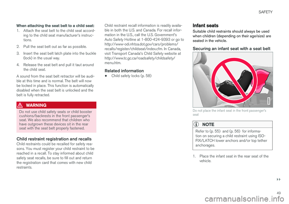
Do not use child safety seats or child booster cushions/backrests in the front passenger'sseat. We also recommend that children whohave outgrown these devices sit in the rearseat with the seat belt properly fastened.
Child restraint registration and recallsChild restraints could be recalled for safety rea- sons. You must register your child restraint to bereached in a recall. To stay informed about childsafety seat recalls, be sure to fill out and returnthe registration card that comes with new childrestraints. Child restraint recall information is readily availa-ble in both the U.S. and Canada. For recall infor-mation in the U.S., call the U.S. Government'sAuto Safety Hotline at 1-800-424-9393 or go tohttp://www-odi.nhtsa.dot.gov/cars/problems/recalls/register/childseat/index.cfm. In Canada,visit Transport Canada's Child Safety website athttp://www.tc.gc.ca/roadsafety/childsafety/menu.htm.
Related information
•
Child safety locks (p. 58)
Infant seats
Suitable child restraints should always be used when children (depending on their age/size) areseated in the vehicle.
Securing an infant seat with a seat belt
G022844
Do not place the infant seat in the front passenger's seat
NOTE
Refer to (p. 55) and (p. 56) for informa- tion on securing a child restraint using ISO-FIX/LATCH lower anchors and/or top tetheranchorages.
1. Place the infant seat in the rear seat of the vehicle.
Page 67 of 396
INSTRUMENTS AND CONTROLS
* Option/accessory.65
Power Meter (see Eco Guide * and Power
Meter * (p. 66)).
Gear indicator: Shows the currently selected gear
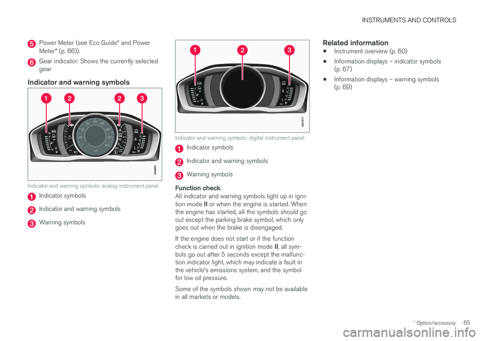
Indicator and warning symbols
Indicator and warning symbols: analog instrument panel
Indicator symbols
Indicator and warning symbols
Warning symbols
Indicator and warning symbols: digital instrument panel
Indicator symbols
Indicator and warning symbols
Warning symbols
Function check
All indicator and warning symbols light up in igni- tion mode II or when the engine is started. When
the engine has started, all the symbols should go out except the parking brake symbol, which onlygoes out when the brake is disengaged. If the engine does not start or if the function check is carried out in ignition mode II, all sym-
bols go out after 5 seconds except the malfunc- tion indicator light, which may indicate a fault inthe vehicle's emissions system, and the symbolfor low oil pressure. Some of the symbols shown may not be available in all markets or models.
Related information
• Instrument overview (p. 60)
• Information displays – indicator symbols(p. 67)
• Information displays – warning symbols(p. 69)
Page 70 of 396
||
INSTRUMENTS AND CONTROLS
* Option/accessory.
68
Malfunction Indicator Light
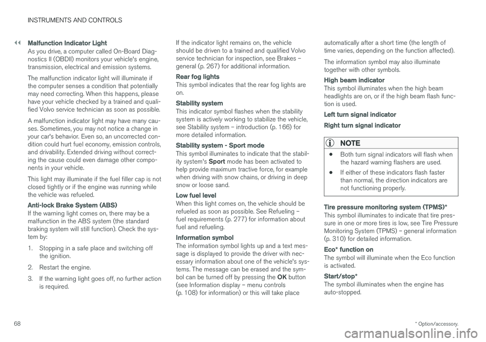
As you drive, a computer called On-Board Diag- nostics II (OBDII) monitors your vehicle's engine,transmission, electrical and emission systems. The malfunction indicator light will illuminate if the computer senses a condition that potentiallymay need correcting. When this happens, pleasehave your vehicle checked by a trained and quali-fied Volvo service technician as soon as possible. A malfunction indicator light may have many cau- ses. Sometimes, you may not notice a change inyour car's behavior. Even so, an uncorrected con-dition could hurt fuel economy, emission controls,and drivability. Extended driving without correct-ing the cause could even damage other compo-nents in your vehicle. This light may illuminate if the fuel filler cap is not closed tightly or if the engine was running whilethe vehicle was refueled.
Anti-lock Brake System (ABS)
If the warning light comes on, there may be a malfunction in the ABS system (the standardbraking system will still function). Check the sys-tem by:
1. Stopping in a safe place and switching off
the ignition.
2. Restart the engine.
3. If the warning light goes off, no further action is required. If the indicator light remains on, the vehicle should be driven to a trained and qualified Volvoservice technician for inspection, see Brakes –general (p. 267) for additional information.
Rear fog lights
This symbol indicates that the rear fog lights are on.
Stability system
This indicator symbol flashes when the stability system is actively working to stabilize the vehicle,see Stability system – introduction (p. 166) formore detailed information.
Stability system - Sport mode
This symbol illuminates to indicate that the stabil- ity system's
Sport mode has been activated to
help provide maximum tractive force, for example when driving with snow chains, or driving in deepsnow or loose sand.
Low fuel level
When this light comes on, the vehicle should be refueled as soon as possible. See Refueling –fuel requirements (p. 277) for information aboutfuel and refueling.
Information symbol
The information symbol lights up and a text mes- sage is displayed to provide the driver with nec-essary information about one of the vehicle's sys-tems. The message can be erased and the sym- bol can be turned off by pressing the OK button
(see Information display – menu controls (p. 108) for information) or this will take place automatically after a short time (the length oftime varies, depending on the function affected). The information symbol may also illuminate together with other symbols.
High beam indicator
This symbol illuminates when the high beam headlights are on, or if the high beam flash func-tion is used.
Left turn signal indicator Right turn signal indicator
NOTE
•
Both turn signal indicators will flash when the hazard warning flashers are used.
• If either of these indicators flash fasterthan normal, the direction indicators arenot functioning properly.
Tire pressure monitoring system (TPMS)
*
This symbol illuminates to indicate that tire pres- sure in one or more tires is low, see Tire PressureMonitoring System (TPMS) – general information(p. 310) for detailed information.
Eco* function on
The symbol will illuminate when the Eco function is activated.
Start/stop *
The symbol illuminates when the engine has auto-stopped.
Page 72 of 396
||
INSTRUMENTS AND CONTROLS
70
Engine temperature
Engine overheating can result from low oil or coolant levels, towing or hard driving at high heatand altitude, or mechanical malfunction. Engineoverheating will be signaled with text and a redwarning triangle in the middle of the instrumentdisplay. The exact text will depend on the degree of overheating. It may range from
High engine
temp Reduce speed to High engine temp
Stop engine. If appropriate, other messages,
such as Coolant level low, Stop safely will
also be displayed. If your engine does overheat so that you must stop the engine, always allowthe engine to cool before attempting to check oiland coolant levels. See Engine compartment – coolant (p. 332) for more information.
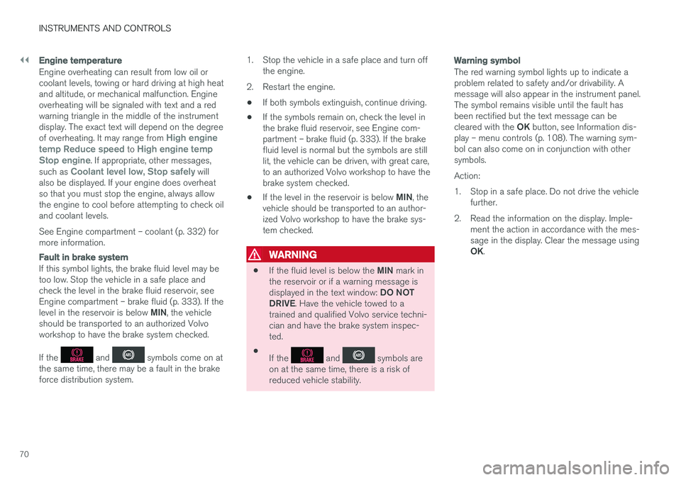
Fault in brake system
If this symbol lights, the brake fluid level may be too low. Stop the vehicle in a safe place andcheck the level in the brake fluid reservoir, seeEngine compartment – brake fluid (p. 333). If the level in the reservoir is below MIN, the vehicle
should be transported to an authorized Volvo workshop to have the brake system checked. If the
and symbols come on at
the same time, there may be a fault in the brake force distribution system. 1. Stop the vehicle in a safe place and turn off
the engine.
2. Restart the engine.
• If both symbols extinguish, continue driving.
• If the symbols remain on, check the level inthe brake fluid reservoir, see Engine com-partment – brake fluid (p. 333). If the brakefluid level is normal but the symbols are stilllit, the vehicle can be driven, with great care,to an authorized Volvo workshop to have thebrake system checked.
• If the level in the reservoir is below
MIN, the
vehicle should be transported to an author-ized Volvo workshop to have the brake sys-tem checked.
WARNING
• If the fluid level is below the
MIN mark in
the reservoir or if a warning message is displayed in the text window: DO NOT
DRIVE . Have the vehicle towed to a
trained and qualified Volvo service techni- cian and have the brake system inspec-ted.
• If the
and symbols are
on at the same time, there is a risk of reduced vehicle stability.
Warning symbol
The red warning symbol lights up to indicate a problem related to safety and/or drivability. Amessage will also appear in the instrument panel.The symbol remains visible until the fault hasbeen rectified but the text message can be cleared with the OK button, see Information dis-
play – menu controls (p. 108). The warning sym- bol can also come on in conjunction with othersymbols. Action:
1. Stop in a safe place. Do not drive the vehicle further.
2. Read the information on the display. Imple- ment the action in accordance with the mes- sage in the display. Clear the message using OK.
Page 73 of 396
INSTRUMENTS AND CONTROLS
}}
71
Reminder – doors not closed
If one of the doors is not closed properly, the
information or warning symbol illuminates
(depending on the vehicle's speed), a graphic will be displayed in instrument panel and an explana- tory text message 3
will also be displayed in the
instrument panel. Stop the vehicle in a safe place as soon as possible and close the door.
If the vehicle is driven at a speed lowerthan approximately 5 mph (7 km/h),the information symbol illuminates.
If the vehicle is driven at a speed higher than approximately 5 mph(7 km/h), the warning symbol illumi-
nates.
If the hood is not closed properly, the warning
symbol illuminates, a graphic will be displayed in instrument panel and an explanatory text mes- sage 3
will also be displayed in the instrument
panel. Stop the vehicle in a safe place as soon as possible and close the hood. If the trunk is not closed properly, the informa-
tion symbol illuminates and a graphic will be dis-
played in instrument panel. Stop the vehicle in a safe place as soon as possible and close thetrunk.
Related information
• Information displays – introduction (p. 63)
• Information displays – indicator symbols(p. 67)
• Engine compartment – coolant (p. 332)
My Car – introduction
The MY CAR menu system provides access to menus for operating many of the vehicle's func-tions, such as setting the clock, door mirrors,lock and alarm settings, etc.
Some of the features or functions are standard; others are optional and vary according to model/market.
OperationUse the buttons on the center console or thesteering wheel keypad to navigate in the menus.
3 Text message applies only to models with the optional digital instrument panel
Page 74 of 396
||
INSTRUMENTS AND CONTROLS
* Option/accessory.
72
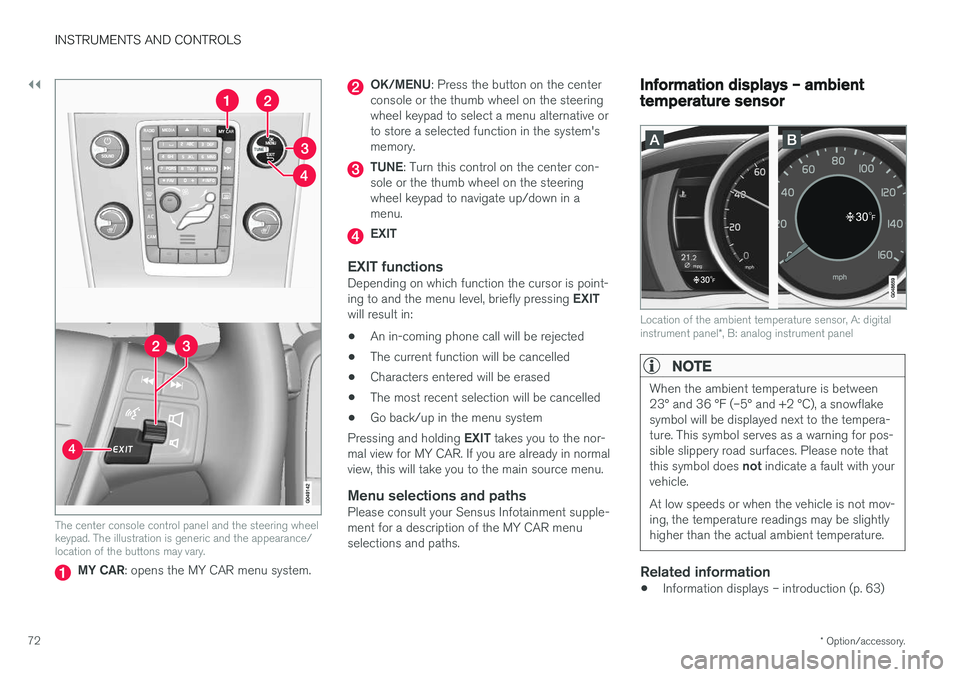
The center console control panel and the steering wheel keypad. The illustration is generic and the appearance/location of the buttons may vary.
MY CAR : opens the MY CAR menu system.
OK/MENU : Press the button on the center
console or the thumb wheel on the steering wheel keypad to select a menu alternative orto store a selected function in the system'smemory.
TUNE : Turn this control on the center con-
sole or the thumb wheel on the steering wheel keypad to navigate up/down in amenu.
EXIT
EXIT functionsDepending on which function the cursor is point- ing to and the menu level, briefly pressing EXIT
will result in:
• An in-coming phone call will be rejected
• The current function will be cancelled
• Characters entered will be erased
• The most recent selection will be cancelled
• Go back/up in the menu system
Pressing and holding EXIT takes you to the nor-
mal view for MY CAR. If you are already in normal view, this will take you to the main source menu.
Menu selections and pathsPlease consult your Sensus Infotainment supple-ment for a description of the MY CAR menuselections and paths.
Information displays – ambient temperature sensor
Location of the ambient temperature sensor, A: digital instrument panel *, B: analog instrument panel
NOTE
When the ambient temperature is between 23° and 36 °F (–5° and +2 °C), a snowflakesymbol will be displayed next to the tempera-ture. This symbol serves as a warning for pos-sible slippery road surfaces. Please note that this symbol does not indicate a fault with your
vehicle. At low speeds or when the vehicle is not mov- ing, the temperature readings may be slightlyhigher than the actual ambient temperature.
Related information
• Information displays – introduction (p. 63)
Page 75 of 396
INSTRUMENTS AND CONTROLS
}}
* Option/accessory.73
Information displays – trip odometer and clock The trip odometers
T1 and T2 and clock are dis-
played in the instrument panel.
Trip odometers
Trip odometer 4
Odometer display
Turn the thumb wheel on the left steering wheel lever to display the desired trip odometer. Press and hold the RESET button on the left
steering wheel lever for at least 1 second to reset the selected trip odometer 5
.
Clock
Clock, digital instrument panel *
Display6
Setting the clock
The clock can be set in the
MY CAR menu sys-
tem. See My Car – introduction (p. 71) for addi- tional information about these menus. Go to
SettingsSystem optionsTime
settings. Set Auto time to ON (check the box)
and select the correct time zone under Location.
Related information
• Information displays – introduction (p. 63)
Inserting/removing remote key The remote key is used to start the engine or to use various electrical functions without startingthe engine.
Inserting and removing the remote key
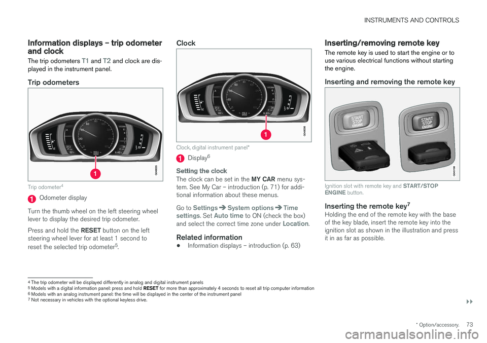
Ignition slot with remote key and
START/STOP
ENGINE button.
Inserting the remote key 7Holding the end of the remote key with the base of the key blade, insert the remote key into theignition slot as shown in the illustration and pressit in as far as possible.
4
The trip odometer will be displayed differently in analog and digital instrument panels
5 Models with a digital information panel: press and hold RESET for more than approximately 4 seconds to reset all trip computer information
6 Models with an analog instrument panel: the time will be displayed in the center of the instrument panel
7
Not necessary in vehicles with the optional keyless drive.
Page 80 of 396

INSTRUMENTS AND CONTROLS
* Option/accessory.
78
Key memory – power driver's seat *
and door mirrors
Each remote key has a memory that enables it to store (remember) the position of the power driv-er's seat and door mirrors when the vehicle islocked with that remote key.
Remote key memory and the power
driver's seat * and door mirrors 11
The key memory has to be activated
for each of
the remote keys used in the vehicle as fol-
lows:
1. Insert a remote key in the ignition slot.2. Go into the MY CAR menu and go to
SettingsCar settingsCar key
memory
3. To activate the remote key memory feature, press ENTER (check the box).
> The remote key is now ready to store the position of the power driver's seat and door mirrors.
Repeat this procedure for each of the vehicle'sremote keys. See My Car – introduction (p. 71) for a descrip- tion of the menu system.
Storing the positions of the power driver's seat/mirrors in the remote key
1. Move the seat and door mirrors to the desired position using the seat and mirror adjustment controls.
2. Exit the vehicle and lock the doors with the remote key (or close the driver's door andpress the lock button on the door handlewith the remote key in your possession onvehicles with the optional keyless drive).
> The positions of the power driver's seatand door mirrors are now stored in the remote key's memory.
NOTE
The remote key's memory feature and the power driver's seat memory function (the set-tings made using the buttons on the side ofthe seat, see the section "Power seat mem-ory function" in Front seats – power seat(p. 76)) work independently of each other.
11This information also applies to vehicles with the optional keyless drive.
Page 82 of 396
||
INSTRUMENTS AND CONTROLS
80
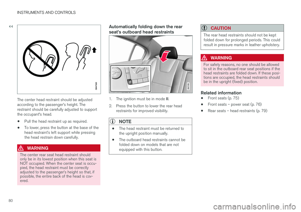
The center head restraint should be adjusted according to the passenger's height. Therestraint should be carefully adjusted to supportthe occupant's head.
• Pull the head restraint up as required.
• To lower, press the button at the base of thehead restraint