lock VOLVO V60 2021 Owners Manual
[x] Cancel search | Manufacturer: VOLVO, Model Year: 2021, Model line: V60, Model: VOLVO V60 2021Pages: 661, PDF Size: 12.68 MB
Page 440 of 661
STARTING AND DRIVING
438
Towing using a towline
This section refers to one vehicle being towed behind another using a towline.
Before towing another vehicle, check applica- ble speed limit regulations.
Preparations and towing
CAUTION
For some transmission variants, it is not possible to shift from P position if theengine is switched off. Contact an author-ized Volvo workshop for assistance towingor call a professional towing service.
CAUTION
Note that the vehicle must always be towed with the wheels rolling forward.
Do not tow a vehicle with automatictransmission at a speed greater than80 km/h (50 mph) or for a distancegreater than 80 km (50 miles).
WARNING
Ignition mode
II must be active – all
airbags are deactivated in ignition mode I.
Always have the remote key in thevehicle when it is towed.
WARNING
The brake and steering servos do not work when the engine is off – it takesabout 5 times more pressure on the brakepedal and steering requires much moreeffort than normal.
1. Turn on the hazard warning flashers.
2. Attach the towline to the towing eyelet.
3. Put the vehicle in ignition mode II – with-
out pressing the brake pedal, turn the start knob clockwise and hold it there for about4 seconds. Release the knob, which willautomatically return to its original position.
4. Move the gear selector to neutral (N) and release the parking brake. If the battery charge level is too low, it may not be possible to release the parkingbrake. Connect an auxiliary battery to thevehicle if the battery is discharged.
> The towing vehicle can now start driv-ing. 5. Keep the towline taut when the towing
vehicle slows down by applying light pres- sure to the brake pedal. This will helpavoid jarring movements.
6. Be prepared to apply the brakes to stop the vehicle.
Jump startingDo not tow the vehicle to start the engine. Usean auxiliary battery if the start battery's chargelevel is so low that the engine cannot bestarted.
CAUTION
Attempting to tow with the engine running could result in damage to the three-waycatalytic converter.
Related information
Attaching and removing the towing eyelet (p. 439)
Hazard warning flashers (p. 159)
Recovery (p. 440)
Jump starting using another battery(p. 431)
Selecting ignition mode (p. 396)
Transmission (p. 406)
Page 441 of 661
STARTING AND DRIVING
}}
439
Attaching and removing the towing eyelet
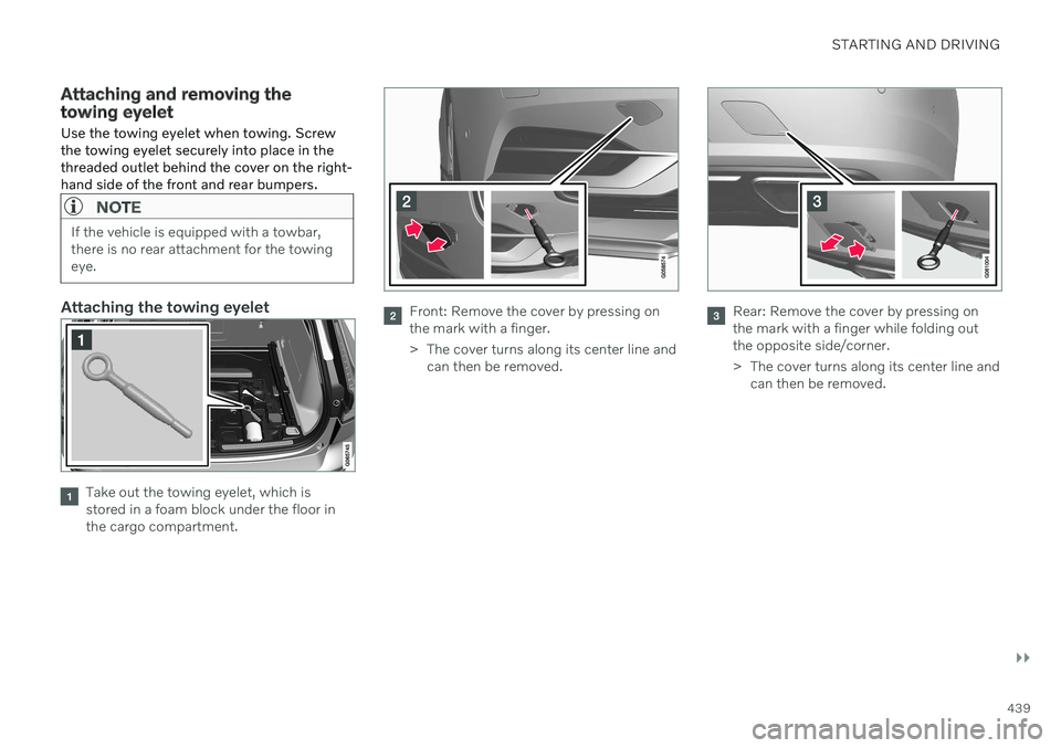
Use the towing eyelet when towing. Screw the towing eyelet securely into place in thethreaded outlet behind the cover on the right-hand side of the front and rear bumpers.
NOTE
If the vehicle is equipped with a towbar, there is no rear attachment for the towingeye.
Attaching the towing eyelet
Take out the towing eyelet, which is stored in a foam block under the floor inthe cargo compartment.
Front: Remove the cover by pressing on the mark with a finger.
> The cover turns along its center line and can then be removed.Rear: Remove the cover by pressing on the mark with a finger while folding outthe opposite side/corner.
> The cover turns along its center line andcan then be removed.
Page 442 of 661
||
STARTING AND DRIVING
* Option/accessory.
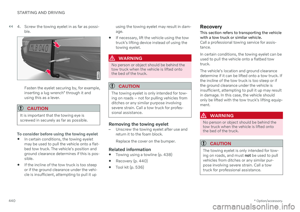
440 4. Screw the towing eyelet in as far as possi-
ble.
Fasten the eyelet securing by, for example, inserting a lug wrench * through it and
using this as a lever.
CAUTION
It is important that the towing eye is screwed in securely as far as possible.
To consider before using the towing eyelet
In certain conditions, the towing eyelet may be used to pull the vehicle onto a flat-bed tow truck. The vehicle's position andground clearance determines if this is pos-sible.
If the incline of the tow truck is too steepor if the ground clearance under the vehi-cle is insufficient, attempting to pull it up using the towing eyelet may result in dam-age.
If necessary, lift the vehicle using the towtruck's lifting device instead of using thetowing eyelet.
WARNING
No person or object should be behind the tow truck when the vehicle is lifted ontothe bed of the truck.
CAUTION
The towing eyelet is only intended for tow- ing on roads – not for pulling vehicles fromditches or any similar purpose involvingsevere strain. Call a tow truck for profes-sional assistance.
Removing the towing eyelet–Unscrew the towing eyelet after use and return it to the foam block. Replace the cover on the bumper.
Related information
Towing using a towline (p. 438)
Recovery (p. 440)
Tool kit (p. 536)
Recovery
This section refers to transporting the vehicle with a tow truck or similar vehicle.
Call a professional towing service for assis- tance. In certain conditions, the towing eyelet can be used to pull the vehicle onto a flatbed towtruck. The vehicle's location and ground clearance determine if it can be lifted onto a tow truck. Ifthe incline of the tow truck is too steep or ifthe ground clearance under the vehicle isinsufficient, attempting to pull it up may resultin damage. In this case, the vehicle shouldonly be lifted with the tow truck's lifting equip-ment.
WARNING
No person or object should be behind the tow truck when the vehicle is lifted ontothe bed of the truck.
CAUTION
The towing eyelet is only intended for tow- ing on roads, and must not be used to pull
vehicles from ditches or any similar pur-pose involving severe strain. Call a towtruck for professional assistance.
Page 445 of 661
STARTING AND DRIVING
}}
* Option/accessory.443
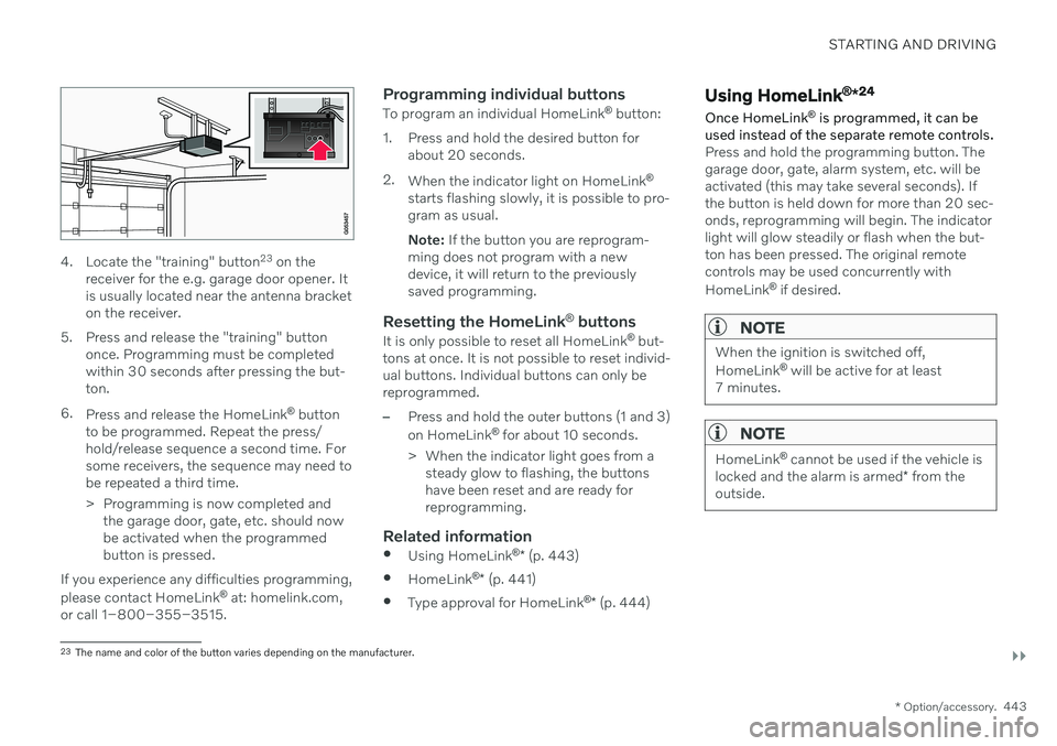
4. Locate the "training" button 23
on the
receiver for the e.g. garage door opener. It is usually located near the antenna bracketon the receiver.
5. Press and release the "training" button once. Programming must be completedwithin 30 seconds after pressing the but-ton.
6. Press and release the HomeLink ®
button
to be programmed. Repeat the press/hold/release sequence a second time. Forsome receivers, the sequence may need tobe repeated a third time.
> Programming is now completed and the garage door, gate, etc. should now be activated when the programmedbutton is pressed.
If you experience any difficulties programming, please contact HomeLink ®
at: homelink.com,
or call 1–800–355–3515.
Programming individual buttons
To program an individual HomeLink ®
button:
1. Press and hold the desired button for about 20 seconds.
2. When the indicator light on HomeLink ®
starts flashing slowly, it is possible to pro- gram as usual. Note: If the button you are reprogram-
ming does not program with a new device, it will return to the previouslysaved programming.
Resetting the HomeLink ®
buttons
It is only possible to reset all HomeLink ®
but-
tons at once. It is not possible to reset individ-ual buttons. Individual buttons can only bereprogrammed.
–Press and hold the outer buttons (1 and 3) on HomeLink ®
for about 10 seconds.
> When the indicator light goes from a steady glow to flashing, the buttons have been reset and are ready forreprogramming.
Related information
Using HomeLink ®
* (p. 443)
HomeLink ®
* (p. 441)
Type approval for HomeLink ®
* (p. 444)
Using HomeLink ®
*24
Once HomeLink ®
is programmed, it can be
used instead of the separate remote controls.
Press and hold the programming button. The garage door, gate, alarm system, etc. will beactivated (this may take several seconds). Ifthe button is held down for more than 20 sec-onds, reprogramming will begin. The indicatorlight will glow steadily or flash when the but-ton has been pressed. The original remotecontrols may be used concurrently with HomeLink ®
if desired.
NOTE
When the ignition is switched off, HomeLink ®
will be active for at least
7 minutes.
NOTE
HomeLink ®
cannot be used if the vehicle is
locked and the alarm is armed * from the
outside.
23 The name and color of the button varies depending on the manufacturer.
Page 507 of 661
AUDIO, MEDIA AND INTERNET
* Option/accessory.505
No or poor Internet connection Factors affecting the Internet connection.
The amount of data transmitted depends on the services or apps currently in use in thevehicle. Streaming music, for example,involves the transmission of a large amount ofdata, and this requires a good connection anda strong signal.
Phone to vehicleInternet connection speed may vary depend-ing on the location of the cellular phone in thevehicle. Move the phone closer to the centerdisplay to increase signal strength. Make surethat nothing is between the phone and centerdisplay that could be blocking the signal.
Phone to network operatorThe speed of the mobile network variesdepending on the coverage in the vehicle'scurrent location. Coverage may be poorer ine.g. tunnels, mountainous areas, deep valleysor indoors. Connection speed is also depend-ent on the subscription you have with yourservice provider.
NOTE
If you experience any problems with data traffic, contact your network service pro-vider.
Restarting the phoneIf you experience any Internet connection problems, it may help to restart your phone.
Related information
Internet-connected vehicle
* (p. 500)
Wi-Fi technology and security (p. 506)
Deleting Wi-Fi networks
Networks that are not needed can be deleted.
1. Tap Settings in the Top view.
2. Proceed to
CommunicationWi-FiSaved networks.
3. Tap
Forget to delete the network.
4. Confirm the selection. > The vehicle will no longer connect tothe deleted network.
Deleting all networksAll networks can be deleted at once by per- forming a factory reset. Please note that alluser data and system settings will be restoredto original default factory settings.
Related information
Internet-connected vehicle
* (p. 500)
No or poor Internet connection (p. 505)
Resetting center display settings (p. 132)
Connecting the vehicle to the Internet viaa phone (Wi-Fi) (p. 501)
Page 537 of 661
WHEELS AND TIRES
}}
* Option/accessory.535
CAUTION
When not in use, the jack
* should be
kept in its storage compartment under the cargo compartment floor.
The jack provided with your vehicle isintended to be used only in temporarysituations such as changing wheels inthe event of a flat tire. Only the jackthat came with your particular modelshould be used to lift the vehicle. If thevehicle needs to be lifted more fre-quently or for a prolonged period, usinga garage jack or hoist is recommended.Always follow this device's instructionsfor use.
Removing a wheelRead through all instructions before starting. Before raising the vehicle using a jack or lift,take out all the tools you will need.
1. Turn on the vehicle's hazard warning
flashers if a wheel change must be per- formed in an area with traffic.
2. Make sure that the parking brake is engaged and put the gear selector in P
position.
3. Place chocks in front of and behind the wheels that are still on the ground. Forexample, use heavy wooden blocks orlarge stones. 4. Using the lug wrench, screw the towing
eye into place as far as possible.
5. Remove the plastic covers from the wheelbolts using the designated tool.
6. With the vehicle still on the ground, use the lug wrench/towing eye to loosen the wheel bolts ½-1 turn by pressing down-ward (counterclockwise). Always start with the locking wheel bolts *.
7. Follow the instructions for safely lifting the vehicle using a jack.
8. Raise the vehicle until the wheel to be changed can move freely. Unscrew the wheel bolts and lift off the wheel.
Installing a wheel1. Clean the contact surfaces between thewheel and the wheel hub. 2. Lift the wheel into place. Tighten the
wheel bolts securely. Do not grease the wheel bolt threads.
3. Lower the vehicle so that the wheel can- not rotate.
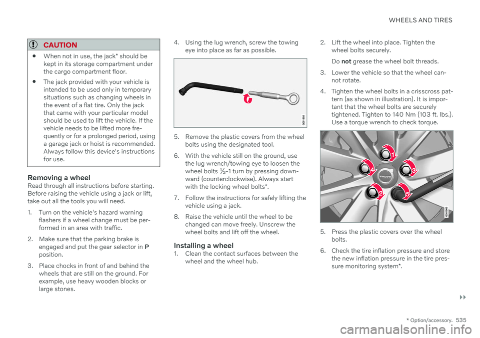
4. Tighten the wheel bolts in a crisscross pat- tern (as shown in illustration). It is impor- tant that the wheel bolts are securelytightened. Tighten to 140 Nm (103 ft. lbs.).Use a torque wrench to check torque.
5. Press the plastic covers over the wheelbolts.
6. Check the tire inflation pressure and store the new inflation pressure in the tire pres- sure monitoring system *.
Page 538 of 661
||
WHEELS AND TIRES
* Option/accessory.
536
WARNING
The wheel bolts may need to be tightened again several days after a wheel change.Temperature fluctuations and vibrationscan cause them to loosen slightly.
NOTE
After inflating a tire, always replace the valve cap to help prevent valve damagecaused by gravel, dirt, etc.
Use plastic valve caps only. Metal capscould corrode and become difficult toremove.
Related information
Hoisting the vehicle (p. 573)
Tool kit (p. 536)
Saving new reference values for tire infla- tion pressure monitoring
* (p. 531)
Tool kit
Tools for e.g. towing or changing wheels are provided in the vehicle's cargo compartment.
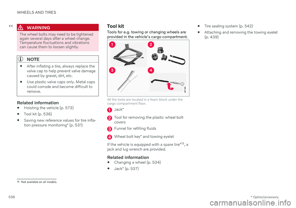
All the tools are located in a foam block under the cargo compartment floor.
Jack *
Tool for removing the plastic wheel bolt covers
Funnel for refilling fluids
Wheel bolt key * and towing eyelet
If the vehicle is equipped with a spare tire *13
, a
jack and lug wrench are provided.
Related information
Changing a wheel (p. 534)
Jack
* (p. 537)
Tire sealing system (p. 542)
Attaching and removing the towing eyelet (p. 439)
13
Not available on all models.
Page 539 of 661
WHEELS AND TIRES
}}
* Option/accessory.537
Jack*
The jack can be used to lift the vehicle to e.g. change a wheel.CAUTION
When not in use, the jack
* should be
kept in its storage compartment under the cargo compartment floor.
The jack provided with your vehicle isintended to be used only in temporarysituations such as changing wheels inthe event of a flat tire. Only the jackthat came with your particular modelshould be used to lift the vehicle. If thevehicle needs to be lifted more fre-quently or for a prolonged period, usinga garage jack or hoist is recommended.Always follow this device's instructionsfor use.
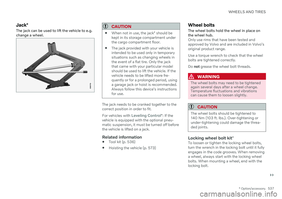
The jack needs to be cranked together to the correct position in order to fit. For vehicles with
Leveling Control*
: If the
vehicle is equipped with the optional pneu- matic suspension, it must be turned off beforethe vehicle is lifted on a jack.
Related information
Tool kit (p. 536)
Hoisting the vehicle (p. 573)
Wheel bolts
The wheel bolts hold the wheel in place on the wheel hub.
Only use rims that have been tested and approved by Volvo and are included in Volvo'soriginal product range. Use a torque wrench to check that the wheel bolts are tightened correctly. Do not grease the wheel bolt threads.
WARNING
The wheel bolts may need to be tightened again several days after a wheel change.Temperature fluctuations and vibrationscan cause them to loosen slightly.
CAUTION
The wheel bolts should be tightened to 140 Nm (103 ft. lbs.). Over-tightening orunder-tightening could damage the threa-ded joints.
Locking wheel bolt kit *To loosen or tighten the locking wheel bolts, turn the wrench in the locking bolt until it fullyengages in the code grooves. When removinga wheel, always start with the locking wheelbolts. When mounting a wheel, end with thelocking bolt.
Page 540 of 661
||
WHEELS AND TIRES
538
CAUTION
Make sure you have a solid connection between bolt and wheel bolt key whenloosening/tightening the wheel bolts.Applying force at an angle could damagethe slots in the wheel bolts and the wheelbolt key and make it impossible to install orremove the wheel.
When the wheel bolt key is not being used, stow it in its designated location in the foamblock under the cargo compartment floor. Thisis important to remember so that the tool isavailable if the vehicle is taken to a workshop.If you lose the key, contact your Volvo retailer.
Related information
Changing a wheel (p. 534)
Tool kit (p. 536)
Spare wheel 14
The spare wheel is a Temporary Spare and can be used to temporarily replace a punc-tured tire on one of the vehicle's regularwheels.
The spare wheel is only intended for tempo- rary use. Replace it with a normal wheel assoon as possible. The driving characteristics of the vehicle change and ground clearance reduces whenthe spare wheel is used. Do not wash the vehi-cle in an automatic car wash while using theTemporary Spare. The recommended tire pressure must be maintained regardless of at which position thetemporary spare wheel is used on the vehicle. If the spare wheel is damaged, a replacement can be purchased from a Volvo retailer.
WARNING
Current legislation prohibits the use of the "Temporary Spare" wheel other than as atemporary replacement for a puncturedtire. It must be replaced as soon as possi-ble by a standard tire. Roadholding andhandling may be affected with the "Tempo-rary Spare" wheel in use.
WARNING
Never drive faster than 80 km/h (50 mph) with a spare tire mounted onthe vehicle.
The vehicle must never be driven withmore than one "Temporary Spare"wheel mounted.
Driving with a spare wheel may alterthe driving characteristics of the vehi-cle. Replace the spare wheel with anormal wheel as soon as possible.
The spare wheel is smaller than thenormal wheel, which affects the vehi-cle's ground clearance. Watch for highcurbs and do not wash the vehicle inan automatic car wash when a sparewheel is mounted.
Follow the manufacturer's recom-mended tire inflation pressure for thespare wheel.
On all-wheel drive vehicles, the driveon the rear axle can be disconnected.
If the spare wheel is mounted on thefront axle, snow chains must not beused.
The spare wheel must not be repaired.
14
Not available on all models.
Page 541 of 661
WHEELS AND TIRES
}}
539
CAUTION
The vehicle must not be driven with tires of different dimensions or with a spare wheelother than the one that came with the vehi-cle. The use of different size wheels canseriously damage your vehicle's transmis-sion.
Related information
Changing a wheel (p. 534)
Recommended tire pressure (p. 529)
Handling the spare wheel 15
Follow these instructions regarding handling the spare wheel.
Accessing the spare wheel
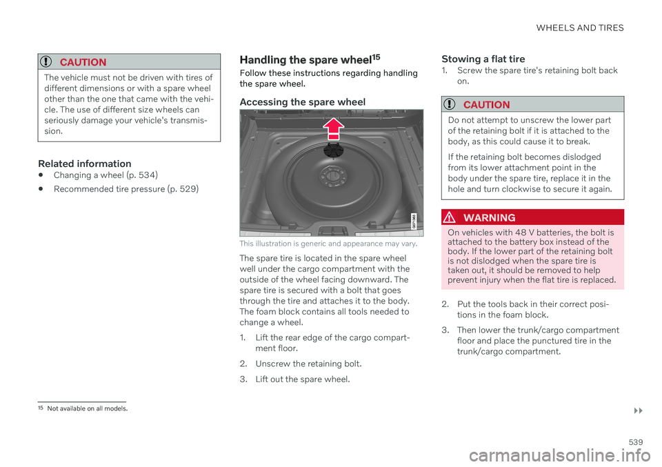
This illustration is generic and appearance may vary.
The spare tire is located in the spare wheel well under the cargo compartment with theoutside of the wheel facing downward. Thespare tire is secured with a bolt that goesthrough the tire and attaches it to the body.The foam block contains all tools needed tochange a wheel.
1. Lift the rear edge of the cargo compart- ment floor.
2. Unscrew the retaining bolt.
3. Lift out the spare wheel.
Stowing a flat tire1. Screw the spare tire's retaining bolt back on.
CAUTION
Do not attempt to unscrew the lower part of the retaining bolt if it is attached to thebody, as this could cause it to break. If the retaining bolt becomes dislodged from its lower attachment point in thebody under the spare tire, replace it in thehole and turn clockwise to secure it again.
WARNING
On vehicles with 48 V batteries, the bolt is attached to the battery box instead of thebody. If the lower part of the retaining boltis not dislodged when the spare tire istaken out, it should be removed to helpprevent injury when the flat tire is replaced.
2. Put the tools back in their correct posi- tions in the foam block.
3. Then lower the trunk/cargo compartment floor and place the punctured tire in the trunk/cargo compartment.
15Not available on all models.