engine VOLVO XC60 TWIN ENGINE 2019 Owners Manual
[x] Cancel search | Manufacturer: VOLVO, Model Year: 2019, Model line: XC60 TWIN ENGINE, Model: VOLVO XC60 TWIN ENGINE 2019Pages: 695, PDF Size: 14.96 MB
Page 522 of 695
AUDIO, MEDIA AND INTERNET
* Option/accessory.520
Streaming media via Bluetooth®
The vehicle's media player is equipped withBluetooth and can play audio files fromBluetooth-enabled external devices such as cel-lular phones and tablets.
In order for the media player to be able to wire-lessly play audio files from an external device, thedevice must be connected to the vehicle viaBluetooth.
Related information
Connecting a device via Bluetooth®
(p. 520)
Connecting a phone to the car via Bluetoothfor the first time (p. 529)
Playing media (p. 514)
Compatible file formats for media (p. 522)
Connecting a device via Bluetooth®
Connect a Bluetooth® device to the vehicle towirelessly play media and give the vehicle anInternet connection if it is available.
Many cellular phones on the market currently
offer wireless Bluetooth® technology, but not allphones are fully compatible with the vehicle. Foradditional information on compatibility, seesupport.volvocars.com.
The procedure for connecting a media device isthe same as for connecting a cellular phone to
the vehicle via Bluetooth®.
Related information
Streaming media via Bluetooth® (p. 520)
Connecting a phone to the car via Bluetoothfor the first time (p. 529)
Playing media (p. 514)
Playing media via the USB port
External audio sources, such as an iPod® orMP3 player, can be connected to the audio sys-tem via the vehicle's USB port.
Devices with rechargeable batteries can becharged when they are connected via the USBport and the ignition is in mode I, II or the engineis running.
The content on the external source can be readfaster if it only contains data of a compatible for-mat. Video files can also be played via the USBport.
Some MP3 players have their own file systemthat the vehicle has support for.
Related information
Connecting a device via the USB port(p. 521)
Playing media (p. 514)
Video (p. 518)
Ignition modes (p. 433)
Technical specifications for USB devices(p. 521)
Apple® CarPlay®* (p. 523)
Android Auto* (p. 526)
Page 570 of 695
||
WHEELS AND TIRES
* Option/accessory.568
NOTE
Always remember to calibrate the Tire Pres-sure Monitoring System when the wheelshave been changed or the tire inflation pres-sure has been corrected according to the tirepressure decal or tire inflation pressure table.
If correct reference values have not been set,the system cannot issue low tire pressurealerts correctly.
The vehicle must be stationary with theengine running to access the calibration but-ton and to start the calibration process.
WARNING
The exhaust gases contain carbon monoxide,which is invisible and odorless but very poi-sonous. For this reason, always perform thecalibration procedure outdoors or in a work-shop with exhaust gas evacuation equipment.
Related information
Recommended tire pressure (p. 565)
Adjusting tire pressure (p. 564)
Viewing tire pressure status in the centerdisplay* (p. 568)
Action when warned of low tire pressure(p. 569)
Tire pressure monitoring system* (p. 565)
Viewing tire pressure status in the
center display*
With the system for tire pressure monitoring 10,tire pressure status can be viewed in the centerdisplay.
Checking status
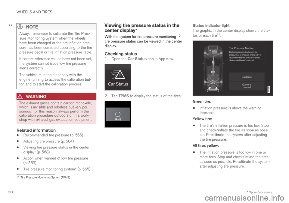
1.Open the Car Status app in App view.
2.Tap TPMS to display the status of the tires.
Status indicator light
The graphic in the center display shows the sta-
tus of each tire11.
Green tire:
Inflation pressure is above the warningthreshold.
Yellow tire:
The tire's inflation pressure is too low. Stopand check/inflate the tire as soon as possi-ble. Recalibrate the system after adjustingthe tire pressure.
All tires yellow:
The inflation pressure is too low in one ormore tires. Stop and check/inflate the tiresas soon as possible. Recalibrate the systemafter adjusting tire pressure.
10Tire Pressure Monitoring System (TPMS)
Page 579 of 695
WHEELS AND TIRES
}}
577
Snow tires
Snow tires are designed for winter driving.
Volvo recommends snow tires with specificdimensions. The tire dimensions vary dependingon engine type. When driving with snow tires, thecorrect type of tires must be mounted on all fourwheels.
NOTE
Contact a Volvo dealer for advice on the bestchoice of rims and tires.
Tips for changing snow tires
When switching between regular tires and snowtires, mark the tires according to which side theywere mounted on, e.g. L for left and R for right.
Studded tires
Studded tires should be broken in by driving500–1000 km (300–600 miles) slowly and gen-tly to help the studs settle properly in the tires.This gives the tire, and especially the studs, alonger service life.
NOTE
Regulations regarding the use of studdedtires vary from country to country.
Tread depth
Road conditions with ice, slush and low tempera-tures place considerably higher demands on tiresthan summer conditions. Volvo therefore recom-mends not driving on snow tires that have a treaddepth of less than 4 mm (0.15 inch).
Related information
When changing wheels (p. 570)
Winter driving (p. 468)
Tread wear indicator (p. 559)
Snow chains
Using snow chains and/or snow tires can helpimprove traction in winter driving conditions.
WARNING
Use Volvo genuine snow chains or equivalentsnow chains that are suitable for the vehiclemodel and the tire and wheel sizes. Only one-sided snow chains are permitted.
If uncertain about snow chains, Volvo recom-mends contacting an authorized Volvo work-shop. Use of the wrong snow chains couldcause serious damage to the vehicle andresult in an accident.
Page 580 of 695
||
WHEELS AND TIRES
578
CAUTION
Snow chains can be used on the vehicle, withthe following restrictions:
Volvo recommends not using snowchains on wheel dimensions larger than18 inches.
Always follow the manufacturer's installa-tion instructions carefully. Install chainsas tightly as possible and retighten peri-odically.
Only put snow chains on the front wheels(also applies to all-wheel drive vehicles).
If accessory, aftermarket or "custom"tires and wheels with different dimen-sions than the original tires and wheelsare used, snow chains in some casesmay NOT be used. Sufficient distancebetween the chains and brakes, suspen-sion and body components must bemaintained.
Check local regulations regarding the useof snow chains before installing.
Never exceed the snow chain manufac-turer's specified maximum speed limit.Under no circumstances should youexceed 50 km/h (30 mph).
Avoid bumps, holes or sharp turns whendriving with snow chains.
Avoid driving on surfaces without snow asthis wears out both the snow chains andthe tires.
The handling of the vehicle can beadversely affected when driving withchains. Avoid fast or sharp turns as wellas locked wheel braking.
Some types of strap-on chains affectbrake components and therefore mustNOT be used.
Consult a Volvo retailer for more informationabout snow chains.
Related information
Winter driving (p. 468)
Tire sealing system16
The temporary tire sealing system can be usedto seal a puncture in a tire or to check andadjust the pressure in the tire.
Models equipped with a spare wheel17 do nothave the tire sealing system.
WARNING
California Proposition 65
Operating, servicing and maintaining a pas-senger vehicle can expose you to chemicalsincluding engine exhaust, carbon monoxide,phthalates, and lead, which are known to theState of California to cause cancer and birthdefects or other reproductive harm. To mini-mize exposure, avoid breathing exhaust, donot idle the engine except as necessary, serv-ice your vehicle in a well ventilated area andwear gloves or wash your hands frequentlywhen servicing your vehicle. For more infor-mation go to www.P65Warnings.ca.gov/passenger-vehicle.
The tire sealing system consists of a compressorand a bottle containing sealing compound. Thesealing functions as a temporary repair.
Page 583 of 695

WHEELS AND TIRES
}}
581
3.Make sure the switch is in the 0 (Off) posi-tion and take out the electric cable and thehose.
4.Unscrew the orange cover on the compres-sor and unscrew the cap on the sealing com-pound bottle.
5. Screw the bottle onto the bottle holder as faras possible.
The bottle and the bottle holder are equip-ped with catches to help prevent the sealingcompound from leaking. Once the bottle isscrewed into place into the bottle holder, itcannot be unscrewed. The bottle can only beremoved by a workshop. Volvo recommendsan authorized Volvo workshop.
WARNING
Do not unscrew the bottle. It is equipped witha catch to prevent leakage.
6.Unscrew the tire's valve cap and screw thehose's valve connector as far as possibleonto the valve.
Be sure the air release valve on the com-pressor's hose is completely closed.
7. Connect the electrical cable to the nearest12 V outlet and start the vehicle.
NOTE
Make sure that none of the vehicle's other12 V sockets are used while the compressoris running.
WARNING
Never leave children unattended in the vehiclewhile the engine is running.
WARNING
Inhaling exhaust fumes could lead to seriousinjury. Never leave the engine running in anenclosed space or a space without sufficientventilation.
8.Start the compressor by moving the switch tothe I (On) position.
WARNING
Never stand next to a tire being inflated withthe compressor. If cracks, bulges, etc. form onthe tire, switch off the compressor immedi-ately. The vehicle should not be driven. Callroadside assistance to have the vehicle towedto a workshop for inspection/replacement ofthe tire. Volvo recommends an authorizedworkshop.
NOTE
When the compressor first starts, air pressuremay temporarily increase up to 6 bar (88 psi)but should decrease again after approxi-mately 30 seconds.
9. Inflate the tire for 7 minutes.
CAUTION
To help avoid overheating, the compressorshould never be used for more than10 minutes at a time.
Page 585 of 695
WHEELS AND TIRES
}}
583
The sealing compound bottle must be replacedafter use. Volvo recommends contacting anauthorized Volvo workshop for replacement.
WARNING
After using the tire sealing system, the vehicleshould not be driven farther than approxi-mately 200 km (120 miles).
NOTE
The compressor is an electric device. Followlocal regulations for disposal.
Related information
Recommended tire pressure (p. 565)
Tire sealing system (p. 578)
Inflate tires with the compressor included inthe tire sealing system (p. 583)
Inflate tires with the compressorincluded in the tire sealing system
The vehicle's original tires can be inflated usingthe compressor in the tire sealing system.
1. The compressor must be switched off. Makesure that the switch is in the 0 (Off) positionand take out the electrical cable and thehose.
2.Unscrew the tire's valve cap and screw thehose's valve connector as far as possibleonto the valve.
Be sure the air release valve on the com-pressor's hose is completely closed.
3. Connect the electrical cable to the nearest12 V outlet and start the vehicle.
WARNING
Inhaling exhaust fumes could lead to seriousinjury. Never leave the engine running in anenclosed space or a space without sufficientventilation.
WARNING
Never leave children unattended in the vehiclewhile the engine is running.
4.Start the compressor by moving the switch tothe I (On) position.
CAUTION
Risk of overheating. The compressor shouldnot be running for longer than 10 minutes ata time.
5. Inflate the tire to the pressure specified onthe tire pressure decal on the driver's sidedoor pillar. If the inflation pressure is toohigh, use the air release valve to release air.
6.Switch off the compressor. Remove the hoseand the electrical cable.
7. Screw the valve cap back onto the tire.
NOTE
After inflating a tire, always replace thevalve cap to help prevent valve damagecaused by gravel, dirt, etc.
Use plastic valve caps only. Metal capscould corrode and become difficult toremove.
NOTE
The compressor is an electric device. Followlocal regulations for disposal.
Page 593 of 695
LOADING, STORAGE AND PASSENGER COMPARTMENT
591
Status indicator lightCauseAction
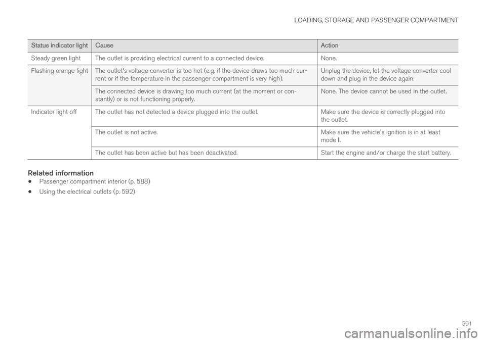
Steady green lightThe outlet is providing electrical current to a connected device.None.
Flashing orange light The outlet's voltage converter is too hot (e.g. if the device draws too much cur-rent or if the temperature in the passenger compartment is very high).Unplug the device, let the voltage converter cooldown and plug in the device again.
The connected device is drawing too much current (at the moment or con-stantly) or is not functioning properly.None. The device cannot be used in the outlet.
Indicator light off The outlet has not detected a device plugged into the outlet.Make sure the device is correctly plugged intothe outlet.
The outlet is not active.Make sure the vehicle's ignition is in at leastmode I.
The outlet has been active but has been deactivated.Start the engine and/or charge the start battery.
Related information
Passenger compartment interior (p. 588)
Using the electrical outlets (p. 592)
Page 594 of 695
LOADING, STORAGE AND PASSENGER COMPARTMENT
* Option/accessory.592
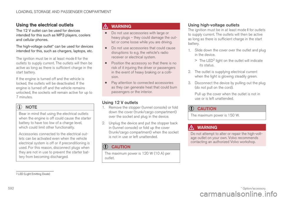
Using the electrical outlets
The 12 V outlet can be used for devicesintended for this such as MP3 players, coolersand cellular phones.
The high-voltage outlet* can be used for devicesintended for this, such as chargers, laptops, etc.
The ignition must be in at least mode I for theoutlets to supply current. The outlets will then beactive as long as there is sufficient charge in thestart battery.
If the engine is turned off and the vehicle islocked, the outlets will be deactivated. If theengine is turned off and the vehicle remainsunlocked, the sockets will remain active for up to7 minutes.
NOTE
Bear in mind that using the electrical outletswhen the engine is off could cause the starterbattery to have too low of a charge level,which could limit other functionality.
Accessories connected to the electrical out-lets can be activated even when the vehicleelectrical system is off or if preconditioning isused. For this reason, disconnect plugs whenthey are not in use to prevent the starter bat-tery from becoming discharged.
WARNING
Do not use accessories with large orheavy plugs – they could damage the out-let or come loose while you are driving.
Do not use accessories that could causedisruptions to e.g. the vehicle's radioreceiver or electrical system.
Position the accessory so that there is norisk of it injuring the driver or passengersin the event of heavy braking or a colli-sion.
Pay attention to connected accessoriesas they can generate heat that could burnpassengers or the interior.
Using 12 V outlets
1. Remove the stopper (tunnel console) or folddown the cover (trunk/cargo compartment)over the socket and plug in the device.
2. Unplug the device and put the stopper backin (tunnel console) or fold up the cover(trunk/cargo compartment) when the socketis not in use or left unattended.
CAUTION
The maximum power is 120 W (10 A) peroutlet.
Using high-voltage outlets
The ignition must be in at least mode I for outletsto supply current. The outlets will then be activeas long as there is sufficient charge in the startbattery.
1.Slide down the cover over the outlet and plugin the device.
>The LED2 light on the outlet will indicateits status.
2. The outlet is supplying electrical currentwhen the light is glowing steadily green.
3. Disconnect the device by pulling out the plug(do not pull on the cord).
Pull up the cover when the outlet is not inuse or is left unattended.
CAUTION
The maximum power is 150 W.
WARNING
Do not attempt to alter or repair the high-volt-age outlet on your own. Volvo recommendscontacting an authorized Volvo workshop.
2LED (Light Emitting Diode)
Page 596 of 695
||
LOADING, STORAGE AND PASSENGER COMPARTMENT
* Option/accessory.594
The illustration is generic – the design may vary.
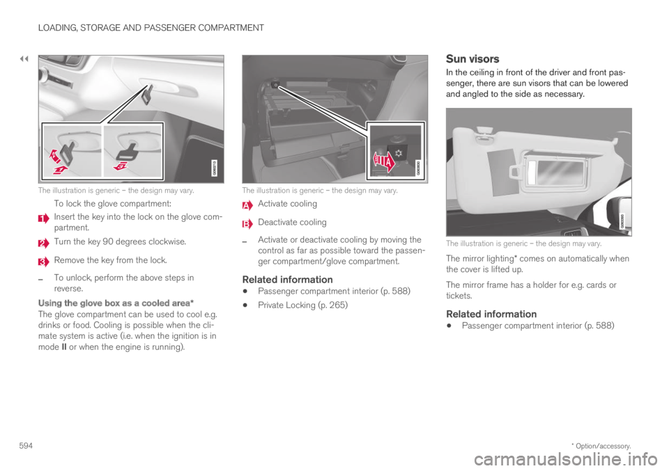
To lock the glove compartment:
Insert the key into the lock on the glove com-partment.
Turn the key 90 degrees clockwise.
Remove the key from the lock.
–To unlock, perform the above steps inreverse.
Using the glove box as a cooled area *
The glove compartment can be used to cool e.g.drinks or food. Cooling is possible when the cli-mate system is active (i.e. when the ignition is inmode II or when the engine is running).
The illustration is generic – the design may vary.
Activate cooling
Deactivate cooling
–Activate or deactivate cooling by moving thecontrol as far as possible toward the passen-ger compartment/glove compartment.
Related information
Passenger compartment interior (p. 588)
Private Locking (p. 265)
Sun visors
In the ceiling in front of the driver and front pas-senger, there are sun visors that can be loweredand angled to the side as necessary.
The illustration is generic – the design may vary.
The mirror lighting* comes on automatically whenthe cover is lifted up.
The mirror frame has a holder for e.g. cards ortickets.
Related information
Passenger compartment interior (p. 588)
Page 597 of 695
LOADING, STORAGE AND PASSENGER COMPARTMENT
}}
* Option/accessory.595
Cargo compartment
The vehicle has a flexible cargo compartmentthat makes it possible to carry and secure largeobjects.
The cargo capacity of the vehicle can be consid-erably increased by folding down the rear seatbackrests. To make loading and unloading easier,the rear section of the vehicle can be raised andlowered using the level control function*. Use theload anchoring eyelets or grocery bag holders tohelp secure objects in place, and the retractablecargo compartment cover* to help concealobjects in the cargo compartment.
If the vehicle is equipped with a temporary sparetire, this is secured to the cargo compartmentfloor under the cover. The towing eyelet and tiresealing system are located under the cargo com-partment floor.
Related information
Loading recommendations (p. 595)
Grocery bag holders (p. 597)
Load anchoring eyelets (p. 598)
Installing and removing the cargo compart-ment cover* (p. 598)
Loading recommendations
There are a number of things to consider whencarrying loads in or on the vehicle.
Load-carrying capacity is determined by the vehi-cle's curb weight. The total weight of all passen-gers and any installed accessories reduces thevehicle's load-carrying capacity by the corres-ponding amount.
WARNING
The vehicle's driving characteristics changedepending on the weight and position of theload.
Loading the cargo compartment/trunk
Position objects so they are pressing againstthe rear seat backrests.
Distribute the load evenly.
Heavy objects should be positioned as lowas possible. Avoid placing heavy objects onfolded-down seat backrests.
Cover sharp corners with a soft cloth or simi-lar to help prevent damage to the upholstery.
Use the load anchoring eyelets and tension-ing straps or similar to secure all objects.
WARNING
In a head-on collision at a speed of 50 km/h(30 mph), an unsecured object weighing 20kg (44 pounds) can reach a projectile weightequivalent to 1000 kg (2200 pounds).
WARNING
If objects are loaded higher than the upperedge of the side windows, leave a 10 cm (4in.) space between the objects and the win-dow. Objects placed closer to this couldimpede the function of the inflatable curtainconcealed inside the headlining.
WARNING
Always secure the load. Otherwise, it may shiftduring heavy braking and injure people in thevehicle.
Cover sharp edges and sharp corners withsomething soft.
Turn off the engine and apply the parkingbrake when loading/unloading long objects.Otherwise, it is possible for the load to reachthe gear lever or gear selector and move it toa drive position – which could cause the vehi-cle to begin rolling.