VOLVO XC90 T8 2017 Owner´s Manual
Manufacturer: VOLVO, Model Year: 2017, Model line: XC90 T8, Model: VOLVO XC90 T8 2017Pages: 580, PDF Size: 10.37 MB
Page 221 of 580
LOADING AND STORAGE
}}
219
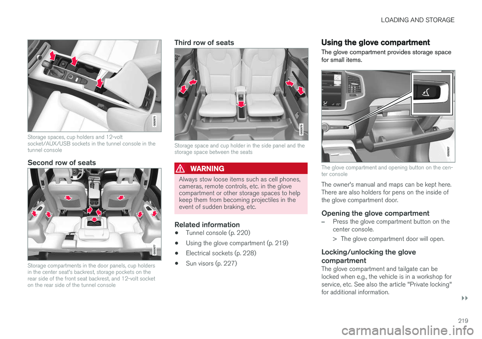
Storage spaces, cup holders and 12-volt socket/AUX/USB sockets in the tunnel console in thetunnel console
Second row of seats
Storage compartments in the door panels, cup holders in the center seat's backrest, storage pockets on therear side of the front seat backrest, and 12-volt socketon the rear side of the tunnel console
Third row of seats
Storage space and cup holder in the side panel and the storage space between the seats
WARNING
Always stow loose items such as cell phones, cameras, remote controls, etc. in the glovecompartment or other storage spaces to helpkeep them from becoming projectiles in theevent of sudden braking, etc.
Related information
•Tunnel console (p. 220)
• Using the glove compartment (p. 219)
• Electrical sockets (p. 228)
• Sun visors (p. 227)
Using the glove compartment
The glove compartment provides storage space for small items.
The glove compartment and opening button on the cen- ter console
The owner's manual and maps can be kept here. There are also holders for pens on the inside ofthe glove compartment door.
Opening the glove compartment
–Press the glove compartment button on the center console.
> The glove compartment door will open.
Locking/unlocking the glove compartment
The glove compartment and tailgate can be locked when e.g., the vehicle is in a workshop forservice, etc. See also the article "Private locking"for additional information.
Page 222 of 580
||
LOADING AND STORAGE
* Option/accessory.
220
Using the glove compartment as a cooler
The glove compartment can be used to cool drinks or food and the cooling feature functionswhen the climate system is active (i.e., when the ignition is in mode II or when the engine is run-
ning).
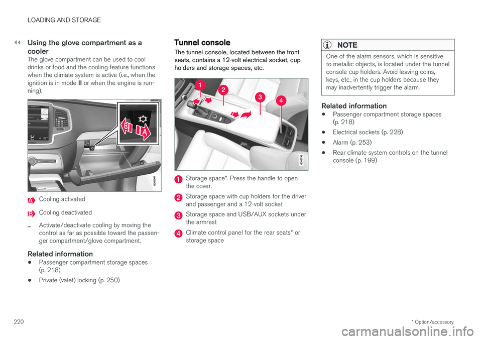
Cooling activated
Cooling deactivated
–Activate/deactivate cooling by moving the control as far as possible toward the passen-ger compartment/glove compartment.
Related information
• Passenger compartment storage spaces(p. 218)
• Private (valet) locking (p. 250)
Tunnel console The tunnel console, located between the front seats, contains a 12-volt electrical socket, cupholders and storage spaces, etc.
Storage space
*. Press the handle to open
the cover.
Storage space with cup holders for the driver and passenger and a 12-volt socket
Storage space and USB/AUX sockets under the armrest
Climate control panel for the rear seats * or
storage space
NOTE
One of the alarm sensors, which is sensitive to metallic objects, is located under the tunnelconsole cup holders. Avoid leaving coins,keys, etc., in the cup holders because theymay inadvertently trigger the alarm.
Related information
• Passenger compartment storage spaces (p. 218)
• Electrical sockets (p. 228)
• Alarm (p. 253)
• Rear climate system controls on the tunnelconsole (p. 199)
Page 223 of 580
LOADING AND STORAGE
}}
* Option/accessory.221
Grocery bag holder
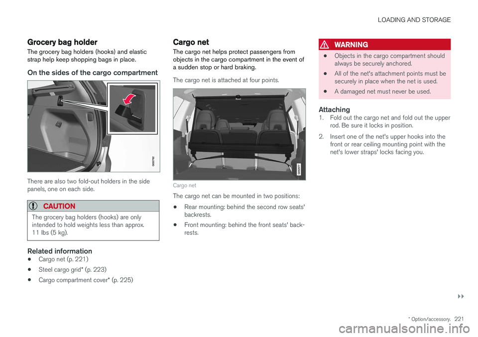
The grocery bag holders (hooks) and elastic strap help keep shopping bags in place.
On the sides of the cargo compartment
There are also two fold-out holders in the side panels, one on each side.
CAUTION
The grocery bag holders (hooks) are only intended to hold weights less than approx.11 lbs (5 kg).
Related information
• Cargo net (p. 221)
• Steel cargo grid
* (p. 223)
• Cargo compartment cover
* (p. 225)
Cargo net
The cargo net helps protect passengers from objects in the cargo compartment in the event ofa sudden stop or hard braking.
The cargo net is attached at four points.
Cargo net
The cargo net can be mounted in two positions: • Rear mounting: behind the second row seats' backrests.
• Front mounting: behind the front seats' back-rests.
WARNING
•
Objects in the cargo compartment should always be securely anchored.
• All of the net's attachment points must besecurely in place when the net is used.
• A damaged net must never be used.
Attaching1. Fold out the cargo net and fold out the upper
rod. Be sure it locks in position.
2. Insert one of the net's upper hooks into the front or rear ceiling mounting point with thenet's lower straps' locks facing you.
Page 224 of 580
||
LOADING AND STORAGE
* Option/accessory.
222 3. Insert the other upper hook into the ceiling
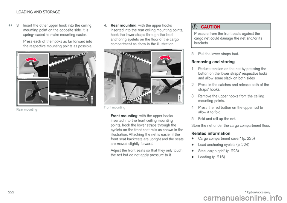
mounting point on the opposite side. It is spring-loaded to make mounting easier. Press each of the hooks as far forward into the respective mounting points as possible.
Rear mounting
4.Rear mounting : with the upper hooks
inserted into the rear ceiling mounting points, hook the lower straps through the loadanchoring eyelets on the floor of the cargocompartment as show in the illustration.
Front mounting
Front mounting : with the upper hooks
inserted into the front ceiling mounting points, hook the lower straps through theeyelets on the front seat rails as shown in theillustration. Attaching the net is easier if thefront seat backrests are upright and the seatsare moved slightly forward. Adjust the front seats so that they only touch the net but do not apply pressure to it.
CAUTION
Pressure from the front seats against the cargo net could damage the net and/or itsbrackets.
5. Pull the lower straps taut.
Removing and storing
1. Reduce tension on the net by pressing the button on the lower straps' respective locks and allow some slack on both sides.
2. Press in the catches and release both of the straps' hooks.
3. Remove the upper hooks from the ceiling mounting points.
4. Press the red button on the upper rod to allow it to fold.
5. Fold and roll up the net. Store the net under the cargo compartment floor.
Related information
• Cargo compartment cover
* (p. 225)
• Load anchoring eyelets (p. 224)
• Steel cargo grid
* (p. 223)
• Loading (p. 216)
Page 225 of 580
LOADING AND STORAGE
}}
* Option/accessory.223
Steel cargo grid *
Your vehicle can be equipped with a steel grid that helps prevent objects in the cargo compart-ment from moving forward into the passengerarea.
The steel grid is made up of the grid itself and two separate mounting brackets. Each of the brackets has a screw cover and there are two plastic sleeves for the grid.
WARNING
• No one should ever be allowed to remain in the cargo compartment when the vehi-cle is moving.
• The steel grid may only be used in therear position described in this article. Theceiling attachment points above the front seats are
not intended to anchor the
steel grid.
• The third row of seats (7-seat models
*
only): these seats must be folded down when the steel grid is mounted in thevehicle.
• After being mounted, be sure that thesteel grid is securely anchored in place.
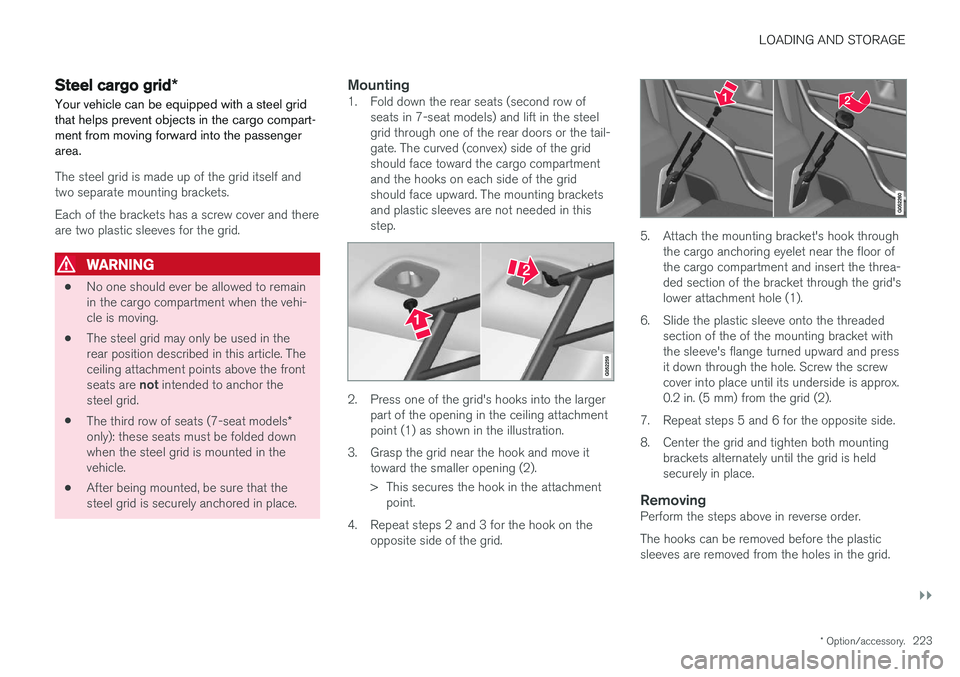
Mounting1. Fold down the rear seats (second row of
seats in 7-seat models) and lift in the steelgrid through one of the rear doors or the tail-gate. The curved (convex) side of the gridshould face toward the cargo compartmentand the hooks on each side of the gridshould face upward. The mounting bracketsand plastic sleeves are not needed in thisstep.
2. Press one of the grid's hooks into the largerpart of the opening in the ceiling attachment point (1) as shown in the illustration.
3. Grasp the grid near the hook and move it toward the smaller opening (2).
> This secures the hook in the attachmentpoint.
4. Repeat steps 2 and 3 for the hook on the opposite side of the grid.
5. Attach the mounting bracket's hook through the cargo anchoring eyelet near the floor of the cargo compartment and insert the threa-ded section of the bracket through the grid'slower attachment hole (1).
6. Slide the plastic sleeve onto the threaded section of the of the mounting bracket withthe sleeve's flange turned upward and pressit down through the hole. Screw the screwcover into place until its underside is approx.0.2 in. (5 mm) from the grid (2).
7. Repeat steps 5 and 6 for the opposite side.
8. Center the grid and tighten both mounting brackets alternately until the grid is held securely in place.
RemovingPerform the steps above in reverse order. The hooks can be removed before the plastic sleeves are removed from the holes in the grid.
Page 226 of 580
||
LOADING AND STORAGE
* Option/accessory.
224
Related information
• Cargo net (p. 221)
• Cargo compartment cover
* (p. 225)
• Load anchoring eyelets (p. 224)
• Loading (p. 216)
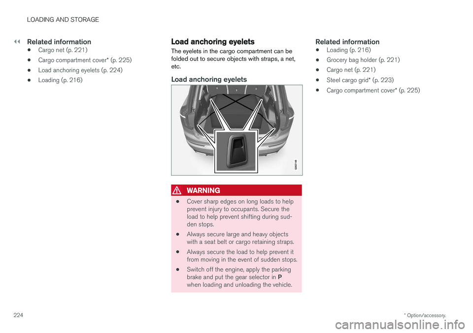
Load anchoring eyelets
The eyelets in the cargo compartment can be folded out to secure objects with straps, a net,etc.
Load anchoring eyelets
WARNING
• Cover sharp edges on long loads to help prevent injury to occupants. Secure theload to help prevent shifting during sud-den stops.
• Always secure large and heavy objectswith a seat belt or cargo retaining straps.
• Always secure the load to help prevent itfrom moving in the event of sudden stops.
• Switch off the engine, apply the parking brake and put the gear selector in
P
when loading and unloading the vehicle.
Related information
• Loading (p. 216)
• Grocery bag holder (p. 221)
• Cargo net (p. 221)
• Steel cargo grid
* (p. 223)
• Cargo compartment cover
* (p. 225)
Page 227 of 580
LOADING AND STORAGE
}}
* Option/accessory.225
Cargo compartment cover *
The cover can be used to conceal objects in the cargo compartment.
Installing the cover 2
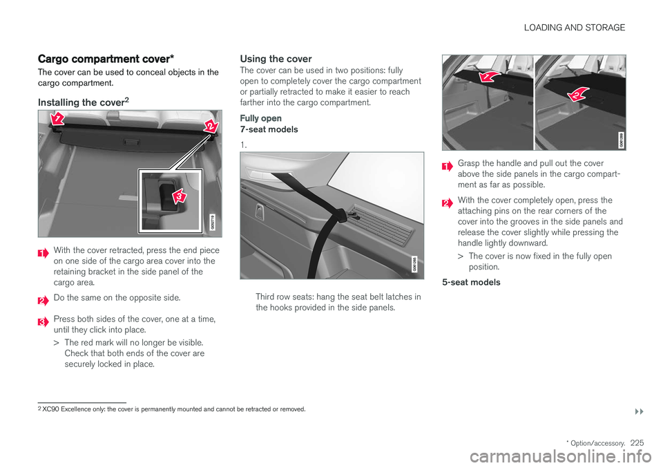
With the cover retracted, press the end piece on one side of the cargo area cover into theretaining bracket in the side panel of thecargo area.
Do the same on the opposite side.
Press both sides of the cover, one at a time, until they click into place.
> The red mark will no longer be visible.
Check that both ends of the cover are securely locked in place.
Using the coverThe cover can be used in two positions: fullyopen to completely cover the cargo compartmentor partially retracted to make it easier to reachfarther into the cargo compartment.
Fully open
7-seat models 1.
Third row seats: hang the seat belt latches in the hooks provided in the side panels.
Grasp the handle and pull out the cover above the side panels in the cargo compart-ment as far as possible.
With the cover completely open, press the attaching pins on the rear corners of thecover into the grooves in the side panels andrelease the cover slightly while pressing thehandle lightly downward.
> The cover is now fixed in the fully openposition.
5-seat models
2 XC90 Excellence only: the cover is permanently mounted and cannot be retracted or removed.
Page 228 of 580
||
LOADING AND STORAGE
226
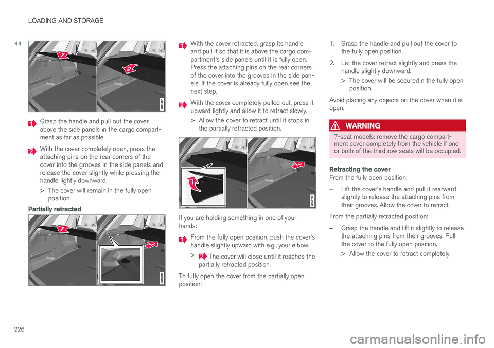
Grasp the handle and pull out the cover above the side panels in the cargo compart-ment as far as possible.
With the cover completely open, press the attaching pins on the rear corners of thecover into the grooves in the side panels andrelease the cover slightly while pressing thehandle lightly downward.
> The cover will remain in the fully openposition.
Partially retracted
With the cover retracted, grasp its handle and pull it so that it is above the cargo com-partment's side panels until it is fully open.Press the attaching pins on the rear cornersof the cover into the grooves in the side pan-els. If the cover is already fully open see thenext step.
With the cover completely pulled out, press it upward lightly and allow it to retract slowly.
> Allow the cover to retract until it stops in the partially retracted position.
If you are holding something in one of your hands:
From the fully open position, push the cover's handle slightly upward with e.g., your elbow. >
The cover will close until it reaches the
partially retracted position.
To fully open the cover from the partially open position: 1. Grasp the handle and pull out the cover to
the fully open position.
2. Let the cover retract slightly and press the handle slightly downward.
> The cover will be secured n the fully openposition.
Avoid placing any objects on the cover when it is open.
WARNING
7-seat models: remove the cargo compart- ment cover completely from the vehicle if oneor both of the third row seats will be occupied.
Retracting the cover
From the fully open position:
–Lift the cover's handle and pull it rearward slightly to release the attaching pins fromtheir grooves. Allow the cover to retract.
From the partially retracted position:
–Grasp the handle and lift it slightly to release the attaching pins from their grooves. Pullthe cover to the fully open position.
> Allow the cover to retract completely.
Page 229 of 580
LOADING AND STORAGE
* Option/accessory.227
Removing the cover1. With the cover retracted, press the button on
one of the cover's ends and lift out that end. For 7-seat models: Release the seat belt latches from the hooks in the side panels.For 5-seat models, see the following step.
2. Carefully lift the cover up/out. > The other end will release automatically.Lift the cover out of the cargo compart-ment.
Related information
• Cargo net (p. 221)
• Steel cargo grid
* (p. 223)
• Loading (p. 216)
• Load anchoring eyelets (p. 224)
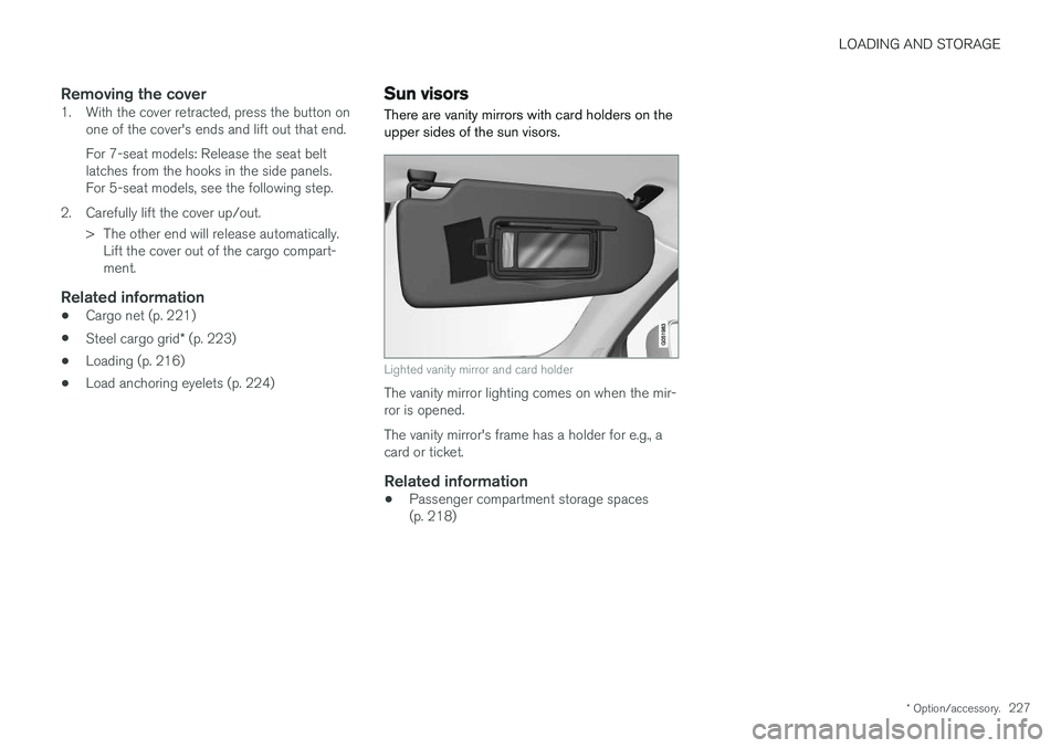
Sun visors There are vanity mirrors with card holders on the upper sides of the sun visors.
Lighted vanity mirror and card holder
The vanity mirror lighting comes on when the mir- ror is opened. The vanity mirror's frame has a holder for e.g., a card or ticket.
Related information
•Passenger compartment storage spaces(p. 218)
Page 230 of 580
LOADING AND STORAGE
* Option/accessory.
228
Electrical sockets There are two 12-volt sockets in the tunnel con- sole, a 120-volt socket on the rear side of thetunnel console, and one 12-volt socket in the cargo area *.
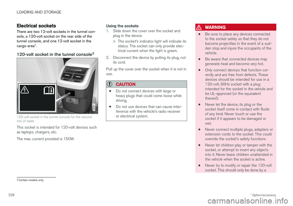
120-volt socket in the tunnel console 3
120-volt socket in the tunnel console for the second row of seats
This socket is intended for 120-volt devices such as laptops, chargers, etc. The max. current provided is 150W.
Using the sockets
1. Slide down the cover over the socket and
plug in the device.
> The socket's indicator light will indicate itsstatus. The socket can only provide elec- trical current when the light is green.
2. Disconnect the device by pulling its plug, not its cord.
Pull up the cover over the socket when it is not inuse.
CAUTION
• Do not connect devices with large or heavy plugs that could come loose whiledriving.
• Do not use devices that can cause inter-ference with the vehicle's radio receiveror electrical system.
WARNING
• Be sure to place any devices connected to the socket safely so that they do notbecome projectiles in the event of a sud-den stop and injure the occupants of thevehicle.
• Be aware that connected devices maygenerate heat and become very hot.
• Only connect devices that function cor-rectly and are free from defects. Thesedevices should be intended for use in a120-volt, 60Hz socket with a plugintended for the socket in the vehicle andbe UL-approved (or the equivalentthereof).
• Never let the device, its plug or thesocket itself come in contact with fluidsof any kind. Never touch or use thesocket if it appears to be damaged orwet.
• Never connect multiple plugs, adapters orextension cords to the socket. This couldoverride the socket's safety functions.
• Never let children play or tamper with thesocket, or attempt to insert any objectsinto it. Never leave children unattended inthe vehicle when the socket is active.
• Never try to modify or repair the 120-voltsocket. This should only be done by a
3
Certain models only.