VOLVO XC90 TWIN ENGINE 2019 Owners Manual
Manufacturer: VOLVO, Model Year: 2019, Model line: XC90 TWIN ENGINE, Model: VOLVO XC90 TWIN ENGINE 2019Pages: 697, PDF Size: 10.33 MB
Page 331 of 697
DRIVER SUPPORT
}}
* Option/accessory. 329
Pilot Assist limitations
Pilot Assist functionality may be reduced in cer-
tain situations.
Pilot Assist is a driver support function designed
to simplify driving and assist the driver in many
situations. However, the driver is always responsi-
ble for maintaining a suitable distance to vehicles
or objects around it and ensuring that the vehicle
is correctly positioned in the traffic lane.
WARNING In some situations, Pilot Assist may have trou-
ble helping the driver properly or may be
deactivated automatically – we advise against
using Pilot Assist in such cases. Examples of
such situations include:
the lane markings are worn, missing or
cross each other.
lane division is unclear, for example, when
the lanes divide or merge or at exits or
when there are multiple sets of markings.
edges or other lines than lane markings
are present on or near the road, e.g.
curbs, joints or repairs to the road sur-
face, edges of barriers, roadside edges or
strong shadows.
the lane is narrow or winding.
the lane contains ridges or holes.
weather conditions are poor, e.g. rain,
snow or fog or slush or reduced visibility
with poor light conditions, backlighting,
wet road surface, etc.
The driver should also note that Pilot Assist
has the following limitations:
High curbs, roadside barriers, temporary
obstacles (traffic cones, safety barriers,
etc.) are not detected. Alternatively, they
may be detected incorrectly as lane mark-
ings, with a subsequent risk of contact
between the vehicle and such obstacles. The driver is responsible for ensuring that
the vehicle maintains a suitable distance
from such obstacles.
The camera and radar sensors do not
have the capacity to detect all oncoming
objects and obstacles in traffic environ-
ments, e.g. potholes, stationary obstacles
or objects that completely or partially
block the route.
Pilot Assist does not "see" pedestrians,
animals, etc.
The recommended steering input is lim-
ited in force, which means that it cannot
always help the driver to steer and keep
the vehicle within the lane.
In vehicles equipped with Sensus
Navigation*, the function is able to use
information from map data, which could
cause variations in performance.
Pilot Assist is switched off if the power
steering is working with reduced power -
e.g. during cooling due to overheating
(see section "Speed-dependent steering
force").
The driver can always correct or adjust steering
assistance provided by Pilot Assist by turning the
steering wheel to the desired position.
Page 332 of 697
||DRIVER SUPPORT
* Option/accessory.
330
Steep roads and/or heavy loadsPilot Assist is primarily intended to be driven on
flat roads. The function may not be able to main-
tain the correct time interval to the vehicle ahead
when driving down steep hills. The driver should
be extra attentive and prepared to apply the
brakes.
Do not use Pilot Assist if the vehicle is carry-
ing a heavy load or towing a trailer.
NOTE Pilot Assist cannot be activated if a trailer,
bike carrier or similar is connected to the
vehicle electrical system.
Other limitations
The
Off Road drive mode cannot be
selected when Pilot Assist is activated.
NOTE The function uses the vehicle's combined
camera and radar unit, which has certain gen-
eral limitations; see sections "Camera limita-
tions" and "Radar sensor limitations".
Related information
Pilot Assist (p. 316)
Speed-dependent steering wheel resistance
(p. 278)
Camera limitations (p. 338)
Radar sensor limitations (p. 333) Pilot Assist* symbols and messages
A number of symbols and messages relating to
Pilot Assist may be displayed in the instrument
panel and/or the head-up display*.
Page 333 of 697

DRIVER SUPPORT
}}
331
Several examples
63
are provided below. The previous illustration
64
shows that Pilot Assist
is set to maintain a speed of 110 km/h (68 mph)
and that there is no target vehicle ahead to fol-
low.
Pilot Assist will not provide any steering assis-
tance because it cannot detect the lane's side
marking lines. The previous illustration
64
shows that Pilot Assist
is set to maintain a speed of 110 km/h (68 mph)
and is following a target vehicle ahead that is
traveling at the same speed.
Pilot Assist will not provide any steering assis-
tance because it cannot detect the lane's side
marking lines. The previous illustration
64
shows that Pilot Assist
is set to maintain a speed of 110 km/h (68 mph)
and is following a target vehicle ahead that is
traveling at the same speed.
In this example, Pilot Assist will also provide
steering assistance because it can detect the
lane's side marking lines. 63
In the following illustration, Road Sign Information (RSI) indicates t\
hat the maximum permitted speed is 130 km/h (80 mph).
64 Note: This illustration is general and details may vary depending on mod\
el.
Page 334 of 697
||DRIVER SUPPORT
* Option/accessory.
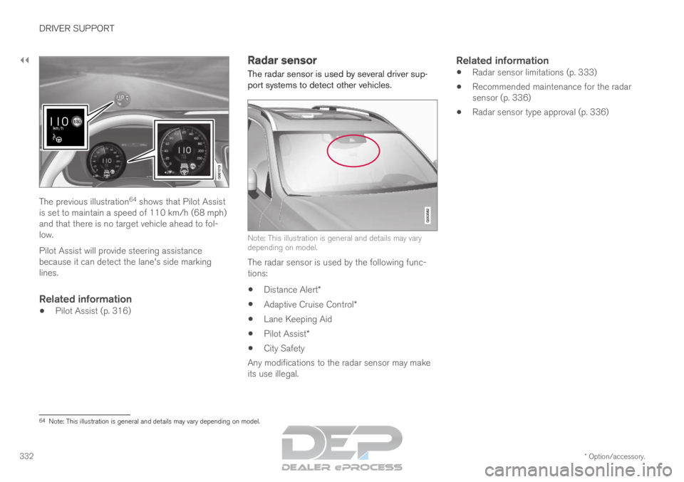
332 The previous illustration
64
shows that Pilot Assist
is set to maintain a speed of 110 km/h (68 mph)
and that there is no target vehicle ahead to fol-
low.
Pilot Assist will provide steering assistance
because it can detect the lane's side marking
lines.
Related information
Pilot Assist (p. 316) Radar sensor
The radar sensor is used by several driver sup-
port systems to detect other vehicles. Note: This illustration is general and details may vary
depending on model.
The radar sensor is used by the following func-
tions:
Distance Alert*
Adaptive Cruise Control*
Lane Keeping Aid
Pilot Assist*
City Safety
Any modifications to the radar sensor may make
its use illegal.
Related information
Radar sensor limitations (p. 333)
Recommended maintenance for the radar
sensor (p. 336)
Radar sensor type approval (p. 336) 64
Note: This illustration is general and details may vary depending on mod\
el.
Page 335 of 697

DRIVER SUPPORT
}}
333
Radar sensor limitations
The radar sensor used by several of the driver
support functions has certain limitations, which
also affect the functions using the radar sensor.
Obstructed camera The area marked in the illustration must be kept free of
decals, objects, solar film, etc.
65 The radar sensor is located on the upper interior
section of the windshield along with the camera.
CAUTION Do not place, affix or mount anything on the
inside or outside of the windshield, or in front
of or around the camera and radar unit – this
could disrupt camera and radar-based func-
tions.
It could cause functions to be reduced, deac-
tivated completely or produce an incorrect
function response. If this symbol and the message
"
Windscreen sensor Sensor
blocked, see Owner's manual" is
displayed in the instrument panel, it
means that the camera and radar sensor are
unable to detect other vehicles, cyclists, pedes-
trians and large animals in front of the vehicle
and that the vehicle's camera and radar-based
functions may be obstructed, reduced, completely
disabled or providing inaccurate responses. The following table shows some of the situations that can cause the mess\
age to be displayed, and suggested actions:
Cause
Action
The area of the windshield in front of the camera/radar sensor is dirty \
or
covered by ice or snow. Clean the windshield in front of the camera/radar sensor and remove dirt\
, ice
and snow.
Thick fog, heavy rain or snow is blocking the radar signals or the camer\
a's
range of visibility. No action. Heavy precipitation may sometimes prevent the camera/radar se\
nsor
from functioning.65
Note: This illustration is general and details may vary depending on mod\
el.
Page 336 of 697
||DRIVER SUPPORT
334
Cause
Action
Water or snow is spraying/swirling up and blocking the radar signals or
the camera's range of visibility. No action. Very wet or snow-covered roads may sometimes prevent the cam-\
era/radar sensor from functioning.
There is dirt between the inside of the windshield and the camera/radar
sensor. Consult a workshop to have the area of the windshield on the inside of t\
he cam-
era's casing cleaned. An authorized Volvo workshop is recommended.
NOTEKeep the windshield in front of the camera
and radar unit clean.
Vehicle speedThe radar sensor's ability to detect a vehicle
ahead is significantly reduced if:
the speed of the vehicle ahead differs greatly
from your vehicle's speed
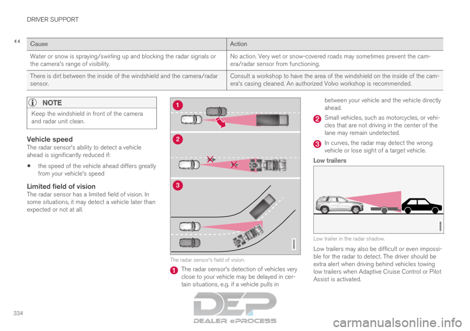
Limited field of visionThe radar sensor has a limited field of vision. In
some situations, it may detect a vehicle later than
expected or not at all. The radar sensor's field of vision.
The radar sensor's detection of vehicles very
close to your vehicle may be delayed in cer-
tain situations, e.g. if a vehicle pulls inbetween your vehicle and the vehicle directly
ahead. Small vehicles, such as motorcycles, or vehi-
cles that are not driving in the center of the
lane may remain undetected.
In curves, the radar may detect the wrong
vehicle or lose sight of a target vehicle.
Low trailers
Low trailer in the radar shadow.
Low trailers may also be difficult or even impossi-
ble for the radar to detect. The driver should be
extra alert when driving behind vehicles towing
low trailers when Adaptive Cruise Control or Pilot
Assist is activated.
Page 337 of 697

DRIVER SUPPORT
335
High temperaturesIf the temperature in the passenger compartment
is very high, the camera/radar sensor will switch
off temporarily for approx. 15 minutes after the
engine is started to protect its electronic compo-
nents. When the temperature has cooled suffi-
ciently, the camera/radar sensor will automati-
cally restart.Damaged windshield
CAUTIONIf there are cracks, scratches or stone chips
on the windshield in front of any of the cam-
era and radar unit "windows" and this covers
an area of about 0.5 × 3.0 mm
(0.02 × 0.12 in.) or more, contact a workshop
to have the windshield replaced – an author-
ized Volvo workshop is recommended.
Failure to take action could result in reduced
performance for the driver support systems
that use the camera and radar unit.
It could cause functions to be reduced, deac-
tivated completely or produce an incorrect
function response.
To avoid the risk of loss of function, malfunc-
tion or reduced function of the driver support
systems that use the radar unit, the following
also apply:
Volvo advises against repairing cracks,
scratches or stone chips in the area in
front of the camera and radar unit – the
entire windshield should instead be
replaced.
Before replacing the windshield, contact
an authorized Volvo workshop to verify
that the right windshield has been
ordered and installed.
The same type of windshield wipers or
wipers approved by Volvo should be used
for replacement.
CAUTION If the windshield is replaced, the camera and
radar unit must be recalibrated by a workshop
to help ensure proper functioning of all of the
vehicle's camera and radar-based systems –
an authorized Volvo workshop is recom-
mended.
Related information
Radar sensor (p. 332)
Page 338 of 697
DRIVER SUPPORT
336Recommended maintenance for the
radar sensor
In order for the camera/radar sensor to function
properly, the area of the windshield in front of the
unit must be kept free of dirt, ice, snow, etc. and
should be washed regularly with water and car
washing detergent.
NOTE
Dirt, ice and snow covering the camera and
radar unit reduce their function and can make
measurement impossible.
It could cause functions to be reduced, deac-
tivated completely or produce an incorrect
function response.
Related information
Radar sensor (p. 332) Radar sensor type approval
The type approval for the vehicle radar sensor in
the ACC 66
, PA 67
and BLIS 68
functions can be
read here.
ACC, PA and BLISUSA & Canada:
FCC ID: L2C0054TR IC: 3432A-0054TR
FCC ID: L2C0055TR IC: 3432A-0055TR
This device complies with Part 15 of the FCC
Rules and with Industry Canada license-exempt
RSS standard(s).
Operation is subject to the following two
conditions:
(1) This device may not cause harmful
interference, and
(2) This device must accept any interference
received, including interference that may cause
undesired operation.
Cet appareil est conforme aux CNR d
Page 339 of 697
DRIVER SUPPORT
* Option/accessory.337
Camera
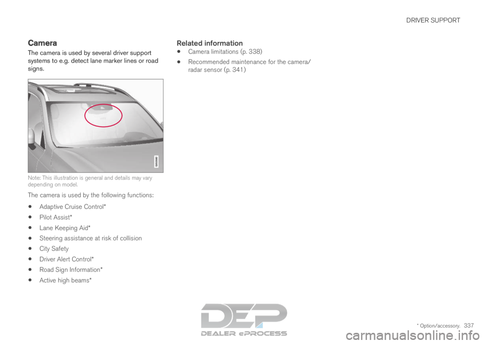
The camera is used by several driver support
systems to e.g. detect lane marker lines or road
signs. Note: This illustration is general and details may vary
depending on model.
The camera is used by the following functions:
Adaptive Cruise Control*
Pilot Assist*
Lane Keeping Aid*
Steering assistance at risk of collision
City Safety
Driver Alert Control*
Road Sign Information*
Active high beams*
Related information
Camera limitations (p. 338)
Recommended maintenance for the camera/
radar sensor (p. 341)
Page 340 of 697

DRIVER SUPPORT
338Camera limitations
The camera used by several of the driver support
functions has certain limitations, which also
affect the functions using the camera.
Reduced visibilityThe camera has the same limitations as the
human eye. In other words, its “vision" is impaired
by adverse weather conditions such as heavy
snowfall/rain, dense fog, swirling dust/snow, etc.
These conditions may reduce the function of sys-
tems that depend on the camera or cause these
systems to temporarily stop functioning.
Strong sunlight, reflections from the road surface,
ice or snow covering the road, a dirty road sur-
face, or unclear lane marker lines may drastically
reduce the camera