display VOLVO XC90 TWIN ENGINE HYBRID 2017 Repair Manual
[x] Cancel search | Manufacturer: VOLVO, Model Year: 2017, Model line: XC90 TWIN ENGINE HYBRID, Model: VOLVO XC90 TWIN ENGINE HYBRID 2017Pages: 584, PDF Size: 14.2 MB
Page 135 of 584
INSTRUMENTS AND CONTROLS
}}
133
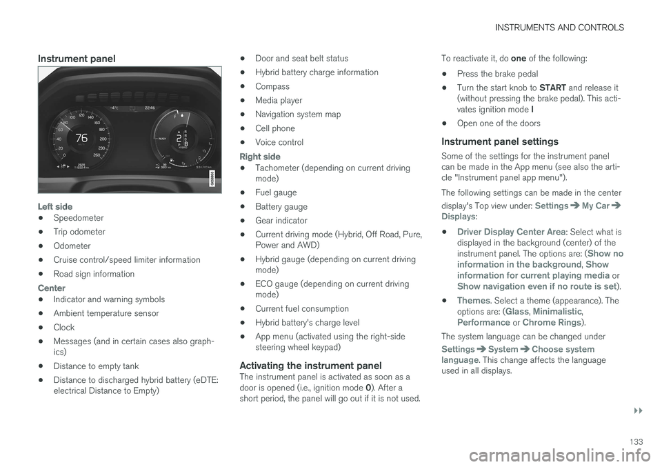
Instrument panel
Left side
•Speedometer
•Trip odometer
•Odometer
•Cruise control/speed limiter information
•Road sign information
Center
•Indicator and warning symbols
•Ambient temperature sensor
•Clock
•Messages (and in certain cases also graph-ics)
•Distance to empty tank
•Distance to discharged hybrid battery (eDTE:electrical Distance to Empty)
•Door and seat belt status
•Hybrid battery charge information
•Compass
•Media player
•Navigation system map
•Cell phone
•Voice control
Right side
•Tachometer (depending on current drivingmode)
•Fuel gauge
•Battery gauge
•Gear indicator
•Current driving mode (Hybrid, Off Road, Pure,Power and AWD)
•Hybrid gauge (depending on current drivingmode)
•ECO gauge (depending on current drivingmode)
•Current fuel consumption
•Hybrid battery's charge level
•App menu (activated using the right-sidesteering wheel keypad)
Activating the instrument panel
The instrument panel is activated as soon as adoor is opened (i.e., ignition mode 0). After ashort period, the panel will go out if it is not used.
To reactivate it, do one of the following:
•Press the brake pedal
•Turn the start knob to START and release it(without pressing the brake pedal). This acti-vates ignition mode I
•Open one of the doors
Instrument panel settings
Some of the settings for the instrument panelcan be made in the App menu (see also the arti-cle "Instrument panel app menu").
The following settings can be made in the center
display's Top view under: SettingsMy CarDisplays:
•Driver Display Center Area: Select what isdisplayed in the background (center) of theinstrument panel. The options are: (Show noinformation in the background, Showinformation for current playing media orShow navigation even if no route is set).
•Themes. Select a theme (appearance). Theoptions are: (Glass, Minimalistic,Performance or Chrome Rings).
The system language can be changed under
SettingsSystemChoose systemlanguage. This change affects the languageused in all displays.
Page 136 of 584

||
INSTRUMENTS AND CONTROLS
134
Related information
•Instrument panel App menu (p. 160)
•Warning symbols in the instrument panel(p. 141)
•Indicator symbols in the instrument panel(p. 130)
•Instrument panel licenses (p. 136)
Hybrid-related information in theinstrument panel
Different types of information will be displayed inthe instrument panel, depending on the drivemode selected. These drive modes offer uniqueways of helping the driver achieve the best pos-sible driving economy.
The vehicle also stores driving statistics that canbe viewed in the form of a bar graph.
Hybrid-unique symbols
The various gauges and indicators in the instru-ment panel show the relationship between theelectric motor's current power consumption andthe remaining power available.
Indicates the currently available outputfrom the electric motor. A solid symbolindicates that the electric motor isbeing used.
Indicates the currently available outputfrom the electric motor. A hollow sym-bol means that the electric motor isnot being used.
Indicates the output level when thegasoline engine starts. A solid symbolindicates that the gasoline engine isbeing used.
Indicates the output level when thegasoline engine will start. A hollowsymbol indicates that the gasolineengine is not being used.
Indicates that the hybrid battery isbeing charged.
Indicates the current charge level inthe electric motor's battery. This indica-tor is located by the hybrid batterygauge in the lower right corner.
eDTE (Electrical Distance To Empty)indicator (distance until the hybrid bat-tery is discharged).
The hybrid gauge
Available electric motor output
This hybrid battery indicator is located betweenthe hybrid gauge and the fuel gauge on the lowerright side of the instrument panel. It indicates thecurrent (charge level) remaining in the hybrid bat-tery, which can be used to power the electricmotor or to heat/cool the vehicle.
Page 137 of 584

INSTRUMENTS AND CONTROLS
135
Power utilized by the driver
The indicator shows the amount of power utilized(requested) by the driver through pressure on theaccelerator pedal. The higher the reading on thescale, the greater the amount of power utilized inthe current gear. The mark between the "light-ning" and "drop" symbols is the point at whichthe electric motor switches off and the gasolineengine starts.
Examples
The vehicle has started but is stationary and nopower is being utilized.
The electric motor alone cannot provide thepower requested and the gasoline engine willstart.
The vehicle is generating current to recharge thebattery, e.g., during moderate braking or duringengine braking on a downslope.
The "Hold" and "Charge" functions
The "Hold" or "Charge" function is activated,
which is shown by the symbol near the bat-tery indicator. See also the article "Maintaining/increasing hybrid battery charge while driving" foradditional information.
Related information
•Drive modes (p. 420)
•Displaying trip computer information (p. 102)
•Displaying trip statistics (p. 104)
•Instrument panel (p. 132)
•Maintaining/increasing the hybrid battery'scharge while driving (p. 420)
Page 138 of 584

INSTRUMENTS AND CONTROLS
136
Instrument panel licenses
BSD 4-clause "Original" or "Old"
License
Copyright ©) 1982, 1986, 1990, 1991, 1993The Regents of the University of California. Allrights reserved.
Redistribution and use in source and binaryforms, with or without modification, are permittedprovided that the following conditions are met:
1. Redistributions of source code must retainthe above copyright notice, this list ofconditions and the following disclaimer.
2. Redistributions in binary form mustreproduce the above copyright notice, this listof conditions and the following disclaimer inthe documentation and/or other materialsprovided with the distribution.
3. All advertising materials mentioning featuresor use of this software must display thefollowing acknowledgment: This productincludes software developed by theUniversity of California, Berkeley and itscontributors.
4. Neither the name of the University nor thenames of its contributors may be used toendorse or promote products derived fromthis software without specific prior writtenpermission.
THIS SOFTWARE IS PROVIDED BY THEREGENTS AND CONTRIBUTORS ``AS IS'' AND
ANY EXPRESS OR IMPLIED WARRANTIES,INCLUDING, BUT NOT LIMITED TO, THEIMPLIED WARRANTIES OF MERCHANTABILITYAND FITNESS FOR A PARTICULAR PURPOSEARE DISCLAIMED. IN NO EVENT SHALL THEREGENTS OR CONTRIBUTORS BE LIABLEFOR ANY DIRECT, INDIRECT, INCIDENTAL,SPECIAL, EXEMPLARY, OR CONSEQUENTIALDAMAGES (INCLUDING, BUT NOT LIMITED TO,PROCUREMENT OF SUBSTITUTE GOODS ORSERVICES; LOSS OF USE, DATA, OR PROFITS;OR BUSINESS INTERRUPTION) HOWEVERCAUSED AND ON ANY THEORY OF LIABILITY,WHETHER IN CONTRACT, STRICT LIABILITY,OR TORT (INCLUDING NEGLIGENCE OROTHERWISE) ARISING IN ANY WAY OUT OFTHE USE OF THIS SOFTWARE, EVEN IFADVISED OF THE POSSIBILITY OF SUCHDAMAGE.
BSD 3-clause "New" or "Revised"
License
Copyright (c) 2011-2014, Yann Collet.
Redistribution and use in source and binaryforms, with or without modification, are permittedprovided that the following conditions are met:
1. Redistributions of source code must retainthe above copyright notice, this list ofconditions and the following disclaimer.
2. Redistributions in binary form mustreproduce the above copyright notice, this listof conditions and the following disclaimer in
the documentation and/or other materialsprovided with the distribution.
3. Neither the name of the organisation nor thenames of its contributors may be used toendorse or promote products derive from thissoftware without specific prior writtenpermission.
THIS SOFTWARE IS PROVIDED BY THECOPYRIGHT HOLDERS AND CONTRIBUTORS"AS IS" AND ANY EXPRESS OR IMPLIEDWARRANTIES, INCLUDING, BUT NOT LIMITEDTO, THE IMPLIED WARRANTIES OFMERCHANTABILITY AND FITNESS FOR APARTICULAR PURPOSE ARE DISCLAIMED. INNO EVENT SHALL THE COPYRIGHT HOLDEROR CONTRIBUTORS BE LIABLE FOR ANYDIRECT, INDIRECT, INCIDENTAL, SPECIAL,EXEMPLARY, OR CONSEQUENTIAL DAMAGES(INCLUDING, BUT NOT LIMITED TO,PROCUREMENT OF SUBSTITUTE GOODS ORSERVICES; LOSS OF USE, DATA, OR PROFITS;OR BUSINESS INTERRUPTION) HOWEVERCAUSED AND ON ANY THEORY OF LIABILITY,WHETHER IN CONTRACT, STRICT LIABILITY,OR TORT (INCLUDING NEGLIGENCE OROTHERWISE) ARISING IN ANY WAY OUT OFTHE USE OF THIS SOFTWARE, EVEN IFADVISED OF THE POSSIBILITY OF SUCHDAMAGE.
Page 144 of 584
||
INSTRUMENTS AND CONTROLS
142
SymbolMeaning
Oil pressure
If the symbol illuminates duringdriving, stop the vehicle, theengine oil level is too low. Stop theengine immediately and check theengine oil level. Add oil if neces-sary. If the oil level is normal andthe symbol remains illuminated,have the vehicle towed to thenearest authorized Volvo work-shop or trained and qualified Volvoservice technician.
Generator not charging
This symbol illuminates duringdriving if a fault has occurred inthe electrical system. Contact anauthorized Volvo workshop ortrained and qualified Volvo servicetechnician.
AUS modelsBCanadian models
WARNING
•If the fluid level is below the MIN mark inthe brake fluid reservoir or if a warningmessage is displayed in the text window:DO NOT DRIVE. Have the vehicle towedto a trained and qualified Volvo servicetechnician and have the brake systeminspected.
•If the BRAKE and ABS symbols illumi-nate at the same time, there is a risk ofreduced vehicle stability.
Door/hood/tailgate/fuel filler door
reminder
It a door, tailgate, the hood or the fuel filler doorare not closed properly, the information or warn-ing symbol will illuminate and a graphic will bedisplayed in the instrument panel.
Related information
•Instrument panel (p. 132)
•Indicator symbols in the instrument panel(p. 130)
Compass
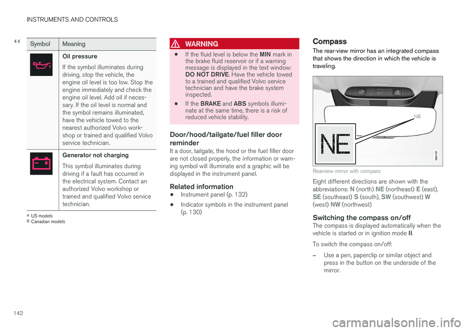
The rear-view mirror has an integrated compassthat shows the direction in which the vehicle istraveling.
Rearview mirror with compass
Eight different directions are shown with theabbreviations: N (north) NE (northeast) E (east),SE (southeast) S (south), SW (southwest) W(west) NW (northwest)
Switching the compass on/off
The compass is displayed automatically when thevehicle is started or in ignition mode II.
To switch the compass on/off:
–Use a pen, paperclip or similar object andpress in the button on the underside of themirror.
Page 145 of 584
INSTRUMENTS AND CONTROLS
}}
* Option/accessory, for more information, see Introduction.143
Related information
•Calibrating the compass (p. 143)
•Ignition modes (p. 400)
Calibrating the compass
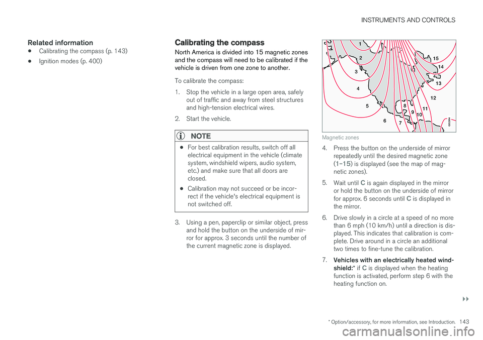
North America is divided into 15 magnetic zonesand the compass will need to be calibrated if thevehicle is driven from one zone to another.
To calibrate the compass:
1.Stop the vehicle in a large open area, safelyout of traffic and away from steel structuresand high-tension electrical wires.
2. Start the vehicle.
NOTE
•For best calibration results, switch off allelectrical equipment in the vehicle (climatesystem, windshield wipers, audio system,etc.) and make sure that all doors areclosed.
•Calibration may not succeed or be incor-rect if the vehicle's electrical equipment isnot switched off.
3. Using a pen, paperclip or similar object, pressand hold the button on the underside of mir-ror for approx. 3 seconds until the number ofthe current magnetic zone is displayed.
15
14
13
12
1198
76
5
4
3
2
1
10
Magnetic zones
4. Press the button on the underside of mirrorrepeatedly until the desired magnetic zone(1–15) is displayed (see the map of mag-netic zones).
5.Wait until C is again displayed in the mirroror hold the button on the underside of mirrorfor approx. 6 seconds until C is displayed inthe mirror.
6.Drive slowly in a circle at a speed of no morethan 6 mph (10 km/h) until a direction is dis-played. This indicates that calibration is com-plete. Drive around in a circle an additionaltwo times to fine-tune the calibration.
7.Vehicles with an electrically heated wind-shield:* if C is displayed when the heatingfunction is activated, perform step 6 with theheating function on.
Page 147 of 584
INSTRUMENTS AND CONTROLS
145
Lightingring posi-tion
Result
With the ignition in mode II or ifthe engine is running:
•The Daytime Running Lightswill be on in daylight condi-
tionsB
•The low beam headlights willautomatically switch on indark conditions
•Tunnel detection will be acti-vated
•Active High Beams (AHB)can be activated
•High beam flash can be used
•Continuous high beams canbe used in dark conditions
Active High Beams On/Off
AThe parking lights will be on in this position, even if the ignitionis switched off. In dark conditions, the rear parking lights illumi-nate automatically when the tailgate is open, regardless of thering's position or ignition mode.BUS models only: The use of Daytime Running Lights can beactivated/deactivated in the center display's Settings menu.
NOTE
Volvo recommends the use of Daytime Run-ning Lights in the United States. The use ofthese lights is mandatory in Canada.
Volvo recommends using the positionwhenever possible.
WARNING
•Daytime Running Lights are a driving aiddesigned to help make the vehicle visibleto other roads users.
•The driver is always responsible foradapting the use of Daytime RunningLights/headlights according to ambientlighting and weather conditions.
Lighting panel
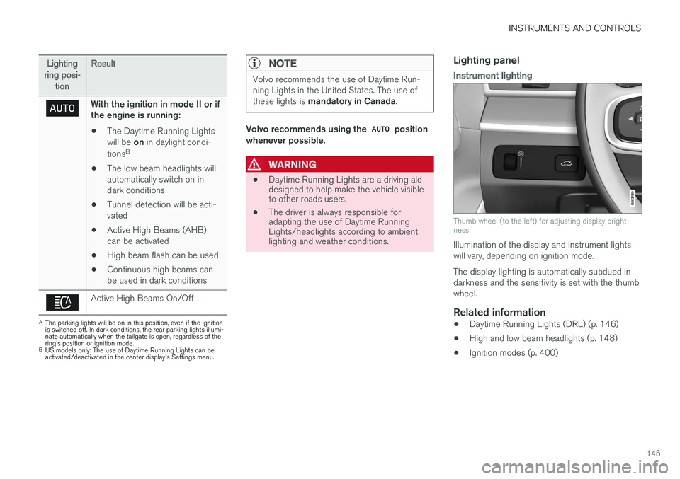
Instrument lighting
Thumb wheel (to the left) for adjusting display bright-ness
Illumination of the display and instrument lightswill vary, depending on ignition mode.
The display lighting is automatically subdued indarkness and the sensitivity is set with the thumbwheel.
Related information
•Daytime Running Lights (DRL) (p. 146)
•High and low beam headlights (p. 148)
•Ignition modes (p. 400)
Page 149 of 584
INSTRUMENTS AND CONTROLS
147
With the lighting ring in the 8 positionand the ignition in mode II or if the engine isrunning:
•In the US: DRL will be off
•In Canada: DRL will be on
With the lighting ring in the position:
•DRL will be on (the low beam headlights willautomatically switch on in dark conditions)
US models only: DRL can be deactivated in thecenter display's Settings view.
With selected, a tunnel detection functionactivates the low beams when the vehicle entersa tunnel.
With the lighting ring in the position:
•DRL will be off and the low beam headlightswill be on
Low beam headlights
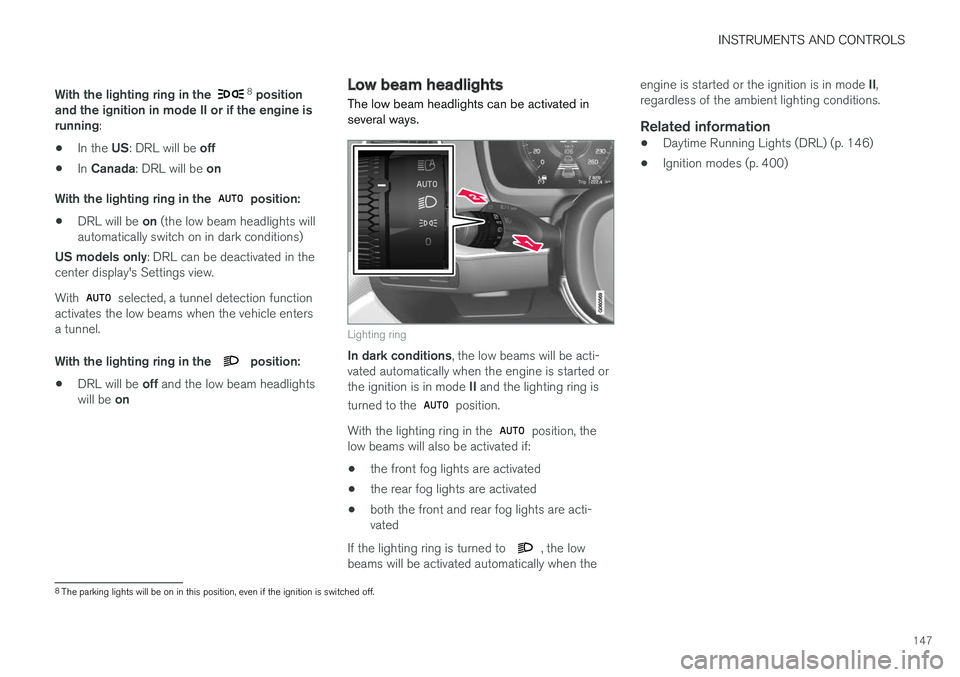
The low beam headlights can be activated inseveral ways.
Lighting ring
In dark conditions, the low beams will be acti-vated automatically when the engine is started orthe ignition is in mode II and the lighting ring is
turned to the position.
With the lighting ring in the position, thelow beams will also be activated if:
•the front fog lights are activated
•the rear fog lights are activated
•both the front and rear fog lights are acti-vated
If the lighting ring is turned to , the lowbeams will be activated automatically when the
engine is started or the ignition is in mode II,regardless of the ambient lighting conditions.
Related information
•Daytime Running Lights (DRL) (p. 146)
•Ignition modes (p. 400)
8The parking lights will be on in this position, even if the ignition is switched off.
Page 150 of 584

INSTRUMENTS AND CONTROLS
148
High and low beam headlights
If the ignition is in mode II or when the engine isstarted, the low beams are activated automati-
cally if the lighting ring is in position . Indark conditions, the low beams will also be on if
the lighting ring is in the position.
Lighting ring
High beam flash
Continuous high beams
High beam flash
Pull the lever slightly toward the steering wheel.The high beams illuminate until the lever isreleased.
Continuous high beams
Continuous high beams are available if the light-
ing ring is turned to 9 or . Toggle tohigh beams by moving the lever forward. Returnto low beams by moving the lever toward thesteering wheel.
The symbol will illuminate in the instrumentpanel when the high beams are on.
Active high beams
The active high beam system uses a camera atthe upper edge of the windshield to detect theheadlights of oncoming vehicles or the taillightsof a vehicle directly ahead. When this happens,the headlights will automatically switch from highbeams to low beams.
When the camera no longer detects anapproaching vehicle or one that is ahead, yourheadlights will switch back to high beams.
Vehicles with halogen headlights 10
When the camera no longer detects the head-lights of an approaching vehicle or the taillightsof a vehicle ahead, your headlights will switchback to high beams after several seconds.
Operation
Activate/deactivate this function by turning the
lighting ring past the position to .
When released, the ring will automatically return
to the position.
If the active high beam function has not beenactivated, switching between high and low beamsmust be done manually.
A white symbol () in the instrument panelindicates that the function has been activated.
When the high beams are on, the symbol willchange to blue.
NOTE
•Keep the windshield in front of the cam-era free of ice, snow, dirt, etc.
•Do not mount or in any way attach any-thing on the windshield that couldobstruct the camera.
If a message is displayed in the instru-ment panel saying that active highbeams are temporarily unavailable,switching between high and low beamswill have to be done manually. However, the light
switch can remain in the position. Thesame applies if a message saying that the wind-shield sensors are blocked and the symbol above
are displayed. The symbol will go out if thishappens.
9When the low beams are on.
10
Halogen headlights are not available on all models.
Page 151 of 584
INSTRUMENTS AND CONTROLS
}}
* Option/accessory, for more information, see Introduction.149
Active high beams may be temporarily unavailable(e.g., in heavy fog or rain). When the systembecomes active again or if the sensors in thewindshield are no longer obscured, the messages
will disappear and the symbol will illumi-nate.
WARNING
•Automatic high beams are a driving aiddesigned to help provide the best possi-ble headlight illumination in good drivingconditions.
•The use of aftermarket or non-Volvoglass can have an adverse effect on theautomatic high beam function.
•The driver is always responsible for man-ually toggling between high and lowbeams when this is required by traffic orweather conditions.
CAUTION
In the following situations, it may be neces-sary to switch between high and low beamsmanually:
•In heavy fog or rain
•In blowing snow or slush
•In bright moonlight
•In freezing rain
•In areas with dim street lighting
•When oncoming vehicles have dim frontlighting
•If there are pedestrians on or near theroad
•If there are reflective objects, such assigns, near the road
•When oncoming vehicles' lights areobscured by e.g., fences, bushes, etc.
•When there are vehicles on connectingroads
•At the top of hills or in dips in the road
•In sharp curves
Related information
•City Safety™ troubleshooting (p. 332)
•Lighting panel and controls (p. 144)
Active Bending Lights*
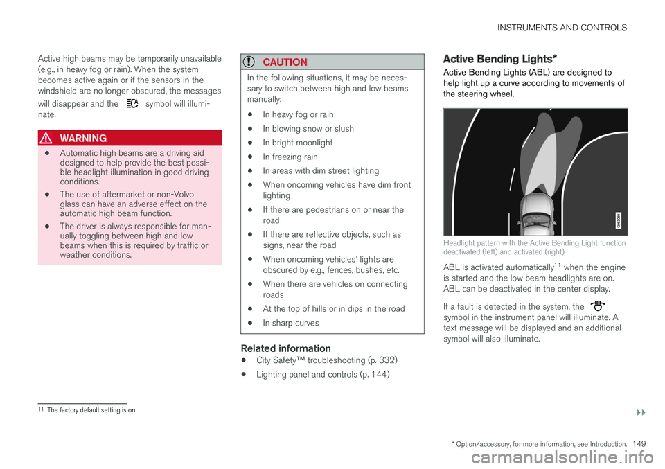
Active Bending Lights (ABL) are designed tohelp light up a curve according to movements ofthe steering wheel.
Headlight pattern with the Active Bending Light functiondeactivated (left) and activated (right)
ABL is activated automatically11 when the engineis started and the low beam headlights are on.ABL can be deactivated in the center display.
If a fault is detected in the system, the symbol in the instrument panel will illuminate. Atext message will be displayed and an additionalsymbol will also illuminate.
11The factory default setting is on.