light YAMAHA DT125R 2002 User Guide
[x] Cancel search | Manufacturer: YAMAHA, Model Year: 2002, Model line: DT125R, Model: YAMAHA DT125R 2002Pages: 96, PDF Size: 2.14 MB
Page 42 of 96

6-4
PERIODIC MAINTENANCE AND MINOR REPAIR
6
EAU03884
NOTE:
8The air filter needs more frequent service if you are riding in unusually wet or dusty areas.
8Hydraulic brake service
9Regularly check and, if necessary, correct the brake fluid level.
9Every two years replace the internal components of the brake master cylinders and calipers, and change the
brake fluid.
9Replace the brake hoses every four years and if cracked or damaged.21
*Carburetor•Check starter (choke) operation.
•Adjust engine idling speed.√√√√√ √
22*Autolube pump•Check operation.
•Bleed if necessary.√√√√
23 Transmission oil•Check oil level.√√√√√ √
•Change.√√
24*Cooling system•Check coolant level and vehicle for coolant leakage.√√√√ √
•Change.Every 3 years
25*Front and rear brake
switches•Check operation.√√√√√ √
26 Moving parts and cables•Lubricate.√√√√ √
27*Lights, signals and
switches•Check operation.
•Adjust headlight beam.√√√√√ √ NO. ITEM CHECK OR MAINTENANCE JOBODOMETER READING (× 1,000 km)
ANNUAL
CHECK
1 6 12 18 24
3MB-9-E8 6/13/01 10:55 AM Page 41
Page 47 of 96
6-9
PERIODIC MAINTENANCE AND MINOR REPAIR
6
EAU01833
Checking the spark plugThe spark plug is an important
engine component, which is easy to
check. Since heat and deposits will
cause any spark plug to slowly erode,
the spark plug should be removed
and checked in accordance with the
periodic maintenance and lubrication
chart. In addition, the condition of the
spark plug can reveal the condition of
the engine.
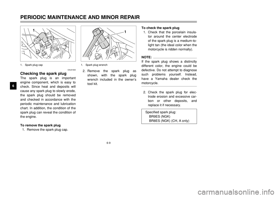
To remove the spark plug
1. Remove the spark plug cap.
1
1. Spark plug cap
To check the spark plug
1. Check that the porcelain insula-
tor around the center electrode
of the spark plug is a medium-to-
light tan (the ideal color when the
motorcycle is ridden normally).NOTE:
If the spark plug shows a distinctly
different color, the engine could be
defective. Do not attempt to diagnose
such problems yourself. Instead,
have a Yamaha dealer check the
motorcycle.2. Check the spark plug for elec-
trode erosion and excessive car-
bon or other deposits, and
replace it if necessary. 2. Remove the spark plug as
shown, with the spark plug
wrench included in the owner’s
tool kit.
1
1. Spark plug wrench
Specified spark plug:
BR9ES (NGK)
BR8ES (NGK) (CH, A only)
3MB-9-E8 6/13/01 10:55 AM Page 46
Page 48 of 96
6-10
PERIODIC MAINTENANCE AND MINOR REPAIR
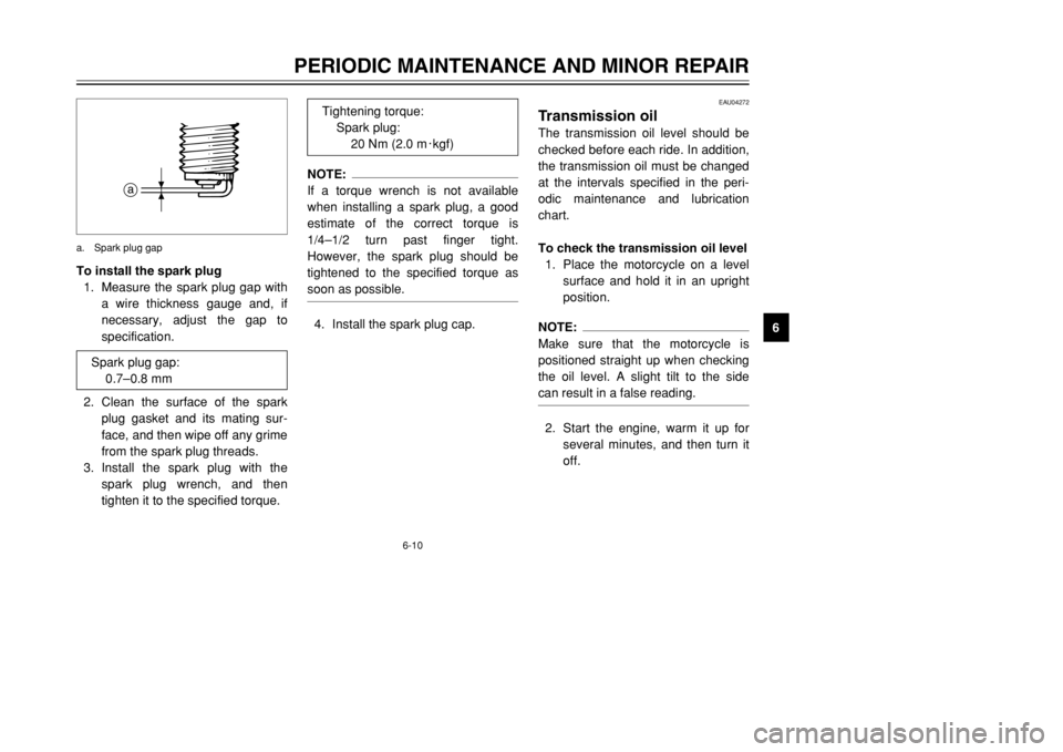
6 To install the spark plug
1. Measure the spark plug gap with
a wire thickness gauge and, if
necessary, adjust the gap to
specification.
2. Clean the surface of the spark
plug gasket and its mating sur-
face, and then wipe off any grime
from the spark plug threads.
3. Install the spark plug with the
spark plug wrench, and then
tighten it to the specified torque.
a
a. Spark plug gap
EAU04272
Transmission oilThe transmission oil level should be
checked before each ride. In addition,
the transmission oil must be changed
at the intervals specified in the peri-
odic maintenance and lubrication
chart.
To check the transmission oil level
1. Place the motorcycle on a level
surface and hold it in an upright
position.NOTE:
Make sure that the motorcycle is
positioned straight up when checking
the oil level. A slight tilt to the side
can result in a false reading.2. Start the engine, warm it up for
several minutes, and then turn it
off.
NOTE:
If a torque wrench is not available
when installing a spark plug, a good
estimate of the correct torque is
1/4–1/2 turn past finger tight.
However, the spark plug should be
tightened to the specified torque as
soon as possible.4. Install the spark plug cap.
Spark plug gap:
0.7–0.8 mmTightening torque:
Spark plug:
20 Nm (2.0 m0kgf)
3MB-9-E8 6/13/01 10:55 AM Page 47
Page 50 of 96
6-12
PERIODIC MAINTENANCE AND MINOR REPAIR
6
EC000077
cC8In order to prevent clutch slip-
page (since the transmission
oil also lubricates the clutch),
do not mix any chemical addi-
tives with the oil.
8Make sure that no foreign
material enters the transmis-
sion.6. Start the engine, and then let it
idle for several minutes while
checking the transmission for oil
leakage. If oil is leaking, immedi-
ately turn off the engine and
check for the cause.
EAU01808
CoolantTo check the coolant level
1. Place the motorcycle on a level
surface and hold it in an upright
position.NOTE:
8The coolant level must be
checked on a cold engine since
the level varies with engine tem-
perature.
8Make sure that the motorcycle is
positioned straight up when
checking the coolant level. A
slight tilt to the side can result in
a false reading.
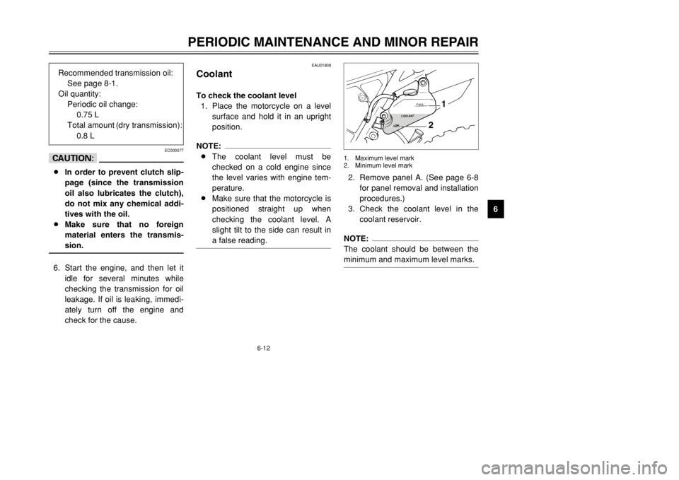
2. Remove panel A. (See page 6-8
for panel removal and installation
procedures.)
3. Check the coolant level in the
coolant reservoir.NOTE:
The coolant should be between the
minimum and maximum level marks.
2
1
1. Maximum level mark
2. Minimum level mark
Recommended transmission oil:
See page 8-1.
Oil quantity:
Periodic oil change:
0.75 L
Total amount (dry transmission):
0.8 L
3MB-9-E8 6/13/01 10:55 AM Page 49
Page 62 of 96
6-24
PERIODIC MAINTENANCE AND MINOR REPAIR
6
EW000109
wA soft or spongy feeling in the
brake pedal can indicate the pres-
ence of air in the hydraulic system.
If there is air in the hydraulic sys-
tem, have a Yamaha dealer bleed
the system before operating the
motorcycle. Air in the hydraulic
system will diminish the braking
performance, which may result in
loss of control and an accident.
EAU00721
Checking the front and rear
brake padsThe front and rear brake pads must
be checked for wear at the intervals
specified in the periodic maintenance
and lubrication chart.
EAU00713
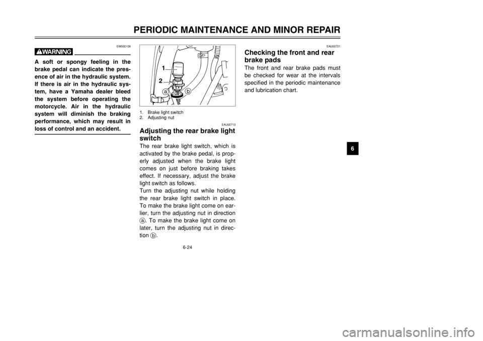
Adjusting the rear brake light
switchThe rear brake light switch, which is
activated by the brake pedal, is prop-
erly adjusted when the brake light
comes on just before braking takes
effect. If necessary, adjust the brake
light switch as follows.
Turn the adjusting nut while holding
the rear brake light switch in place.
To make the brake light come on ear-
lier, turn the adjusting nut in direction
a. To make the brake light come on
later, turn the adjusting nut in direc-
tion b.
b
a 1
2
1. Brake light switch
2. Adjusting nut
3MB-9-E8 6/13/01 10:55 AM Page 61
Page 74 of 96
6-36
PERIODIC MAINTENANCE AND MINOR REPAIR
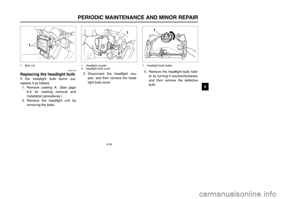
6 4. Remove the headlight bulb hold-
er by turning it counterclockwise,
and then remove the defective
bulb.
1
1. Headlight bulb holder
3. Disconnect the headlight cou-
pler, and then remove the head-
light bulb cover.
1
2
1. Headlight coupler
2. Headlight bulb cover
EAU01158
Replacing the headlight bulbIf the headlight bulb burns out,
replace it as follows.
1. Remove cowling A. (See page
6-5 for cowling removal and
installation procedures.)
2. Remove the headlight unit by
removing the bolts.
1
1. Bolt (×2)
3MB-9-E8 6/13/01 10:55 AM Page 73
Page 75 of 96
6-37
PERIODIC MAINTENANCE AND MINOR REPAIR
6
EAU03497
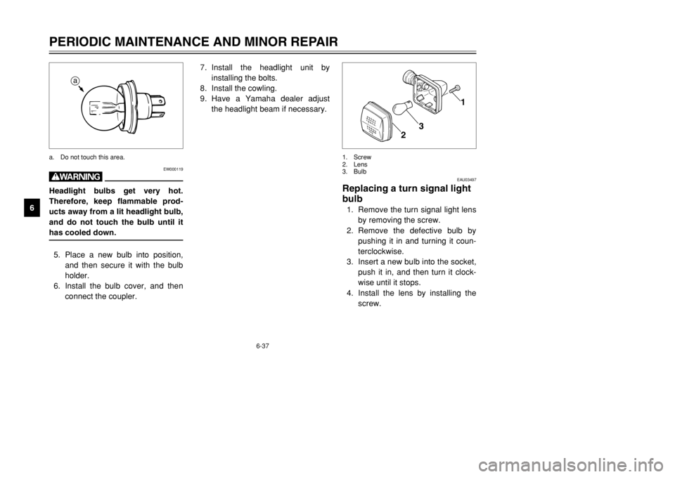
Replacing a turn signal light
bulb1. Remove the turn signal light lens
by removing the screw.
2. Remove the defective bulb by
pushing it in and turning it coun-
terclockwise.
3. Insert a new bulb into the socket,
push it in, and then turn it clock-
wise until it stops.
4. Install the lens by installing the
screw.
1
2
3
1. Screw
2. Lens
3. Bulb
7. Install the headlight unit by
installing the bolts.
8. Install the cowling.
9. Have a Yamaha dealer adjust
the headlight beam if necessary.
EW000119
wHeadlight bulbs get very hot.
Therefore, keep flammable prod-
ucts away from a lit headlight bulb,
and do not touch the bulb until it
has cooled down.5. Place a new bulb into position,
and then secure it with the bulb
holder.
6. Install the bulb cover, and then
connect the coupler.
a
a. Do not touch this area.
3MB-9-E8 6/13/01 10:55 AM Page 74
Page 76 of 96
6-38
PERIODIC MAINTENANCE AND MINOR REPAIR
6
EC000108
cCDo not overtighten the screws,
otherwise the lens may break.
EAU01623
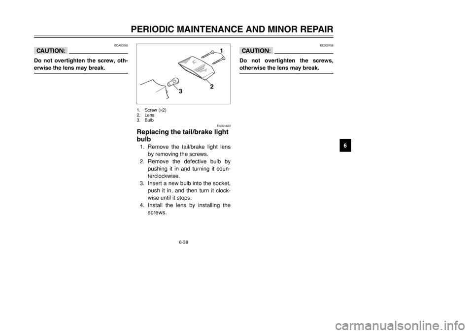
Replacing the tail/brake light
bulb1. Remove the tail/brake light lens
by removing the screws.
2. Remove the defective bulb by
pushing it in and turning it coun-
terclockwise.
3. Insert a new bulb into the socket,
push it in, and then turn it clock-
wise until it stops.
4. Install the lens by installing the
screws.
1
2
3
1. Screw (×2)
2. Lens
3. Bulb
ECA00065
cCDo not overtighten the screw, oth-
erwise the lens may break.
3MB-9-E8 6/13/01 10:55 AM Page 75
Page 85 of 96
7-2
MOTORCYCLE CARE AND STORAGE
78Do not use any harsh chemical
products on plastic parts. Be
sure to avoid using cloths or
sponges which have been in
contact with strong or abra-
sive cleaning products, sol-
vent or thinner, fuel (gasoline),
rust removers or inhibitors,
brake fluid, antifreeze or elec-
trolyte.
8Do not use high-pressure
washers or steam-jet cleaners
since they cause water seep-
age and deterioration in the
following areas: seals (of
wheel and swingarm bearings,
fork and brakes), electric com-
ponents (couplers, connec-
tors, instruments, switches
and lights), breather hoses
and vents.8For motorcycles equipped
with a windshield: Do not use
strong cleaners or hard
sponges as they will cause
dulling or scratching. Some
cleaning compounds for plas-
tic may leave scratches on the
windshield. Test the product
on a small hidden part of the
windshield to make sure that it
does not leave any marks. If
the windshield is scratched,
use a quality plastic polishing
compound after washing.
After normal useRemove dirt with warm water, a mild
detergent, and a soft, clean sponge,
and then rinse thoroughly with clean
water. Use a toothbrush or bottle-
brush for hard-to-reach areas.
Stubborn dirt and insects will come
off more easily if the area is covered
with a wet cloth for a few minutes
before cleaning.After riding in the rain, near the sea
or on salt-sprayed roadsSince sea salt or salt sprayed on
roads during winter are extremely
corrosive in combination with water,
carry out the following steps after
each ride in the rain, near the sea or
on salt-sprayed roads.NOTE:
Salt sprayed on roads in the winter
may remain well into spring.1. Clean the motorcycle with cold
water and a mild detergent, after
the engine has cooled down.
ECA00012
cCDo not use warm water since it
increases the corrosive action of
the salt.2. Apply a corrosion protection
spray on all metal, including
chrome- and nickel-plated, sur-
faces to prevent corrosion.
3MB-9-E8 6/13/01 10:55 AM Page 84
Page 92 of 96

8-4
SPECIFICATIONS
8
Battery
Type GM3-3B
Voltage, capacity 12 V, 3 AH
Headlight typeConventional incandescent bulb
Bulb voltage, wattage ×quantity
Headlight 12 V, 45/40 W ×1
Tail/brake light 12 V, 5/21 W ×1
Front turn signal light 12 V, 21 W ×2
Rear turn signal light 12 V, 21 W ×2
Auxiliary light 12 V, 4 W ×1
12 V, 3.4 W ×1 (GB only)
Meter lighting 12 V, 3.4 W ×2
Neutral indicator light 12 V, 3.4 W ×1
High beam indicator light 12 V, 3.4 W ×1
Oil level indicator light 12 V, 3.4 W ×1
Turn indicator light 12 V, 3.4 W ×1
Fuse10 A
3MB-9-E8 6/13/01 10:55 AM Page 91