light YAMAHA DT125R 2002 Owners Manual
[x] Cancel search | Manufacturer: YAMAHA, Model Year: 2002, Model line: DT125R, Model: YAMAHA DT125R 2002Pages: 96, PDF Size: 2.14 MB
Page 6 of 96

EAU00009
TABLE OF CONTENTS
GIVE SAFETY THE RIGHT OF WAY ............... 1-1
DESCRIPTION .................................................. 2-1
Left view ......................................................... 2-1
Right view ....................................................... 2-2
Controls and instruments ............................... 2-3
INSTRUMENT AND CONTROL FUNCTIONS .. 3-1
Main switch ..................................................... 3-1
Indicator and warning lights ............................ 3-1
Speedometer unit .......................................... 3-2
Tachometer .................................................... 3-2
Coolant temperature gauge ............................ 3-3
Handlebar switches ........................................ 3-3
Clutch lever .................................................... 3-4
Shift pedal ...................................................... 3-4
Brake lever ..................................................... 3-5
Brake pedal .................................................... 3-5
Fuel tank cap .................................................. 3-5
Fuel (except for Switzerland and Austria) ...... 3-6
Fuel (for Switzerland and Austria) ................. 3-6
Catalytic converter
(for Switzerland and Austria) ....................... 3-7
2-stroke engine oil .......................................... 3-8
Fuel cock ........................................................ 3-9
Starter (choke) lever ..................................... 3-10Kickstarter .................................................... 3-10
Steering lock ................................................. 3-10
Seat .............................................................. 3-11
Helmet holder ............................................... 3-12
Adjusting the shock absorber assembly ....... 3-12
Carrier .......................................................... 3-14
YEIS handling precautions .......................... 3-14
YPVS ............................................................ 3-14
Sidestand ..................................................... 3-15
Ignition circuit cut-off system ........................ 3-16
PRE-OPERATION CHECKS ............................. 4-1
Pre-operation check list .................................. 4-1
OPERATION AND IMPORTANT
RIDING POINTS ............................................... 5-1
Starting a cold engine .................................... 5-1
Starting a warm engine .................................. 5-2
Shifting ........................................................... 5-2
Recommended shift points
(for Switzerland only) .................................. 5-3
Tips for reducing fuel consumption ................ 5-3
Engine break-in .............................................. 5-4
Parking ........................................................... 5-5
123
45
3MB-9-E8 6/13/01 10:55 AM Page 5
Page 7 of 96

PERIODIC MAINTENANCE AND
MINOR REPAIR ................................................ 6-1
Owner’s tool kit ............................................... 6-1
Periodic maintenance and lubrication chart ... 6-2
Removing and installing cowlings .................. 6-5
Removing and installing panels ...................... 6-7
Checking the spark plug ................................. 6-9
Transmission oil ........................................... 6-10
Coolant ......................................................... 6-12
Changing the coolant ................................... 6-14
Cleaning the air filter element........................ 6-16
Adjusting the carburetor ............................... 6-17
Adjusting the engine idling speed ................ 6-17
Adjusting the throttle cable free play ............ 6-18
Tires ............................................................. 6-19
Spoke wheels ............................................... 6-21
Adjusting the clutch lever free play ............... 6-22
Adjusting the brake lever free play ............... 6-23
Adjusting the brake pedal position ............... 6-23
Adjusting the rear brake light switch ............. 6-24
Checking the front and rear brake pads ....... 6-24
Checking the brake fluid level ...................... 6-25
Changing the brake fluid .............................. 6-26
Drive chain slack .......................................... 6-27
Lubricating the drive chain ........................... 6-28
Checking and lubricating the cables ............. 6-29Checking and lubricating the
throttle grip and cable ................................ 6-29
Adjusting the Autolube pump ....................... 6-30
Checking and lubricating the brake and
shift pedals ................................................ 6-30
Checking and lubricating the brake and
clutch levers .............................................. 6-30
Checking and lubricating the sidestand ....... 6-31
Checking the front fork ................................. 6-31
Checking the steering ................................... 6-32
Checking the wheel bearings ....................... 6-32
Battery .......................................................... 6-33
Replacing the fuse ....................................... 6-35
Replacing the headlight bulb ........................ 6-36
Replacing a turn signal light bulb ................. 6-37
Replacing the tail/brake light bulb ................ 6-38
Supporting the motorcycle ............................ 6-39
Front wheel ................................................... 6-39
Rear wheel ................................................... 6-42
Troubleshooting ............................................ 6-43
Troubleshooting charts ................................. 6-44
MOTORCYCLE CARE AND STORAGE ........... 7-1
Care ................................................................ 7-1
Storage ........................................................... 7-4
TABLE OF CONTENTS6
7
3MB-9-E8 6/13/01 10:55 AM Page 6
Page 11 of 96
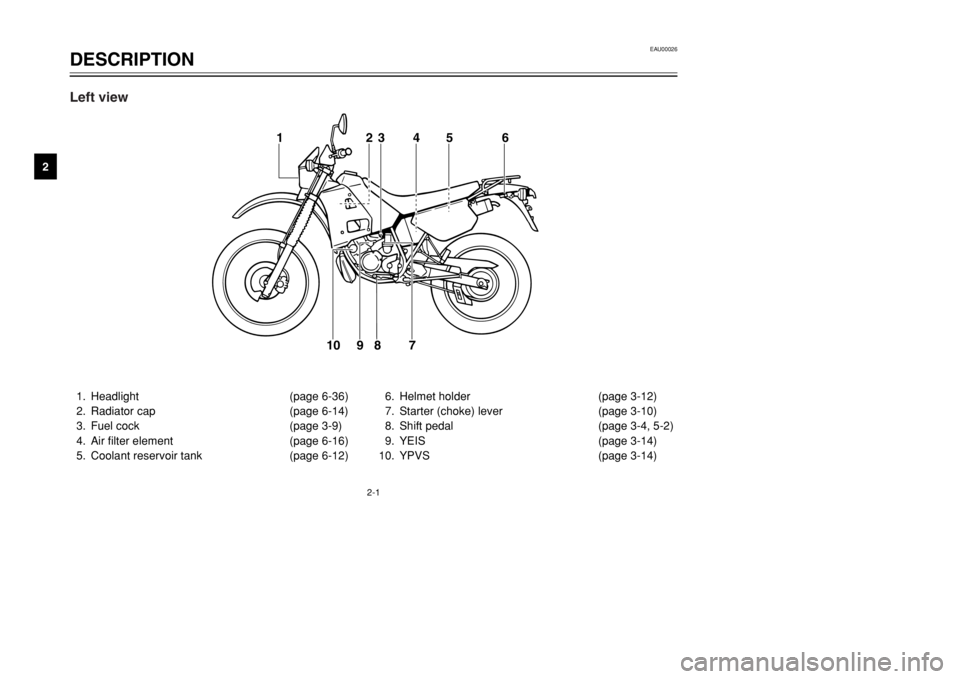
2-1
EAU00026
DESCRIPTION
2
1. Headlight (page 6-36)
2. Radiator cap (page 6-14)
3. Fuel cock (page 3-9)
4. Air filter element (page 6-16)
5. Coolant reservoir tank (page 6-12)6. Helmet holder (page 3-12)
7. Starter (choke) lever (page 3-10)
8. Shift pedal (page 3-4, 5-2)
9. YEIS (page 3-14)
10. YPVS (page 3-14)
1
23 4 5 6
7 8
9 10
Left view
3MB-9-E8 6/13/01 10:55 AM Page 10
Page 14 of 96
3-1
EAU00027
INSTRUMENT AND CONTROL FUNCTIONS
3
EAU00028
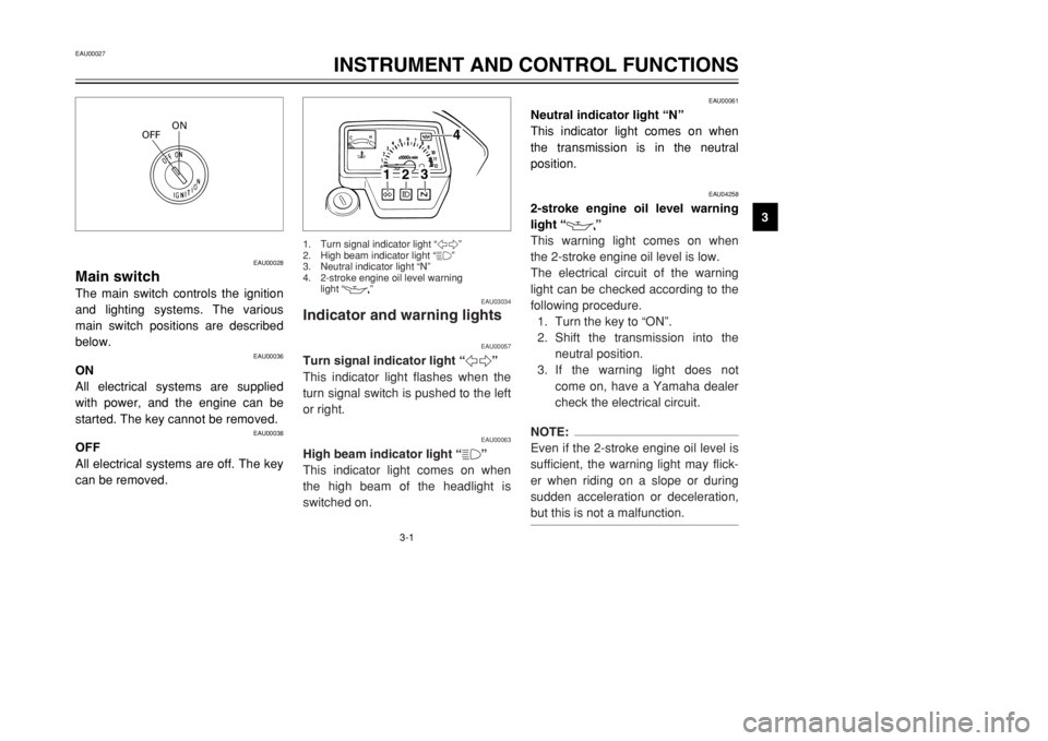
Main switchThe main switch controls the ignition
and lighting systems. The various
main switch positions are described
below.
EAU00036
ON
All electrical systems are supplied
with power, and the engine can be
started. The key cannot be removed.
EAU00038
OFF
All electrical systems are off. The key
can be removed.
EAU00061
Neutral indicator light “N”
This indicator light comes on when
the transmission is in the neutral
position.
EAU04258
2-stroke engine oil level warning
light “
7
”
This warning light comes on when
the 2-stroke engine oil level is low.
The electrical circuit of the warning
light can be checked according to the
following procedure.
1. Turn the key to “ON”.
2. Shift the transmission into the
neutral position.
3. If the warning light does not
come on, have a Yamaha dealer
check the electrical circuit.
NOTE:
Even if the 2-stroke engine oil level is
sufficient, the warning light may flick-
er when riding on a slope or during
sudden acceleration or deceleration,
but this is not a malfunction.
ON
OFF
EAU03034
Indicator and warning lights
EAU00057
Turn signal indicator light “5”
This indicator light flashes when the
turn signal switch is pushed to the left
or right.
EAU00063
High beam indicator light “&”
This indicator light comes on when
the high beam of the headlight is
switched on.
1
2
3
4
1. Turn signal indicator light “5”
2. High beam indicator light “&”
3. Neutral indicator light “N”
4. 2-stroke engine oil level warning
light “
7
”
3MB-9-E8 6/13/01 10:55 AM Page 13
Page 16 of 96
3-3
INSTRUMENT AND CONTROL FUNCTIONS
3
EAU01652
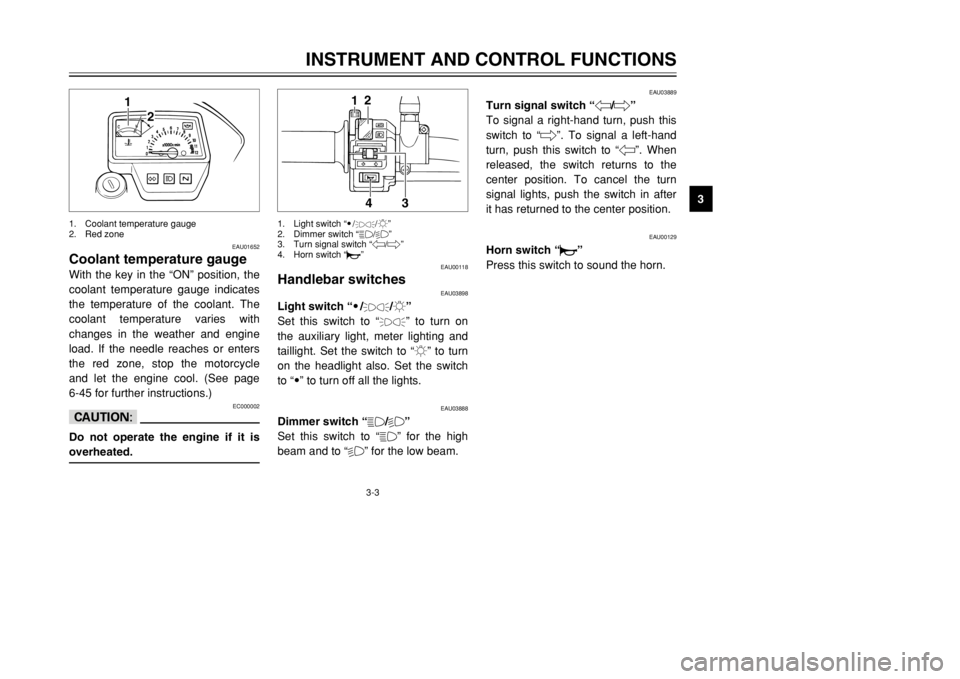
Coolant temperature gaugeWith the key in the “ON” position, the
coolant temperature gauge indicates
the temperature of the coolant. The
coolant temperature varies with
changes in the weather and engine
load. If the needle reaches or enters
the red zone, stop the motorcycle
and let the engine cool. (See page
6-45 for further instructions.)
EC000002
cCDo not operate the engine if it is
overheated.
EAU03889
Turn signal switch “4/6”
To signal a right-hand turn, push this
switch to “6”. To signal a left-hand
turn, push this switch to “4”. When
released, the switch returns to the
center position. To cancel the turn
signal lights, push the switch in after
it has returned to the center position.
EAU00129
Horn switch “*”
Press this switch to sound the horn.
1
2
1. Coolant temperature gauge
2. Red zone
EAU00118
Handlebar switches
EAU03898
Light switch “9/
'
/:”
Set this switch to “'
” to turn on
the auxiliary light, meter lighting and
taillight. Set the switch to “:” to turn
on the headlight also. Set the switch
to “9” to turn off all the lights.
EAU03888
Dimmer switch “&/%”
Set this switch to “&” for the high
beam and to “%” for the low beam.
2
1
3
4
1. Light switch “9/
'
/:”
2. Dimmer switch “&/%”
3. Turn signal switch “4/6”
4. Horn switch “*”
3MB-9-E8 6/13/01 10:55 AM Page 15
Page 23 of 96
3-10
INSTRUMENT AND CONTROL FUNCTIONS
3
EAU03839
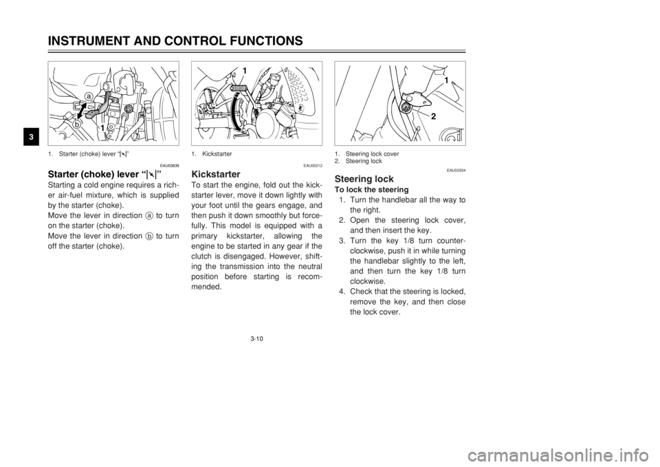
Starter (choke) lever“1”Starting a cold engine requires a rich-
er air-fuel mixture, which is supplied
by the starter (choke).
Move the lever in direction ato turn
on the starter (choke).
Move the lever in direction bto turn
off the starter (choke).
a
b
1
1. Starter (choke) lever “1”
EAU00212
KickstarterTo start the engine, fold out the kick-
starter lever, move it down lightly with
your foot until the gears engage, and
then push it down smoothly but force-
fully. This model is equipped with a
primary kickstarter, allowing the
engine to be started in any gear if the
clutch is disengaged. However, shift-
ing the transmission into the neutral
position before starting is recom-
mended.
1
1. Kickstarter
EAU02934
Steering lockTo lock the steering
1. Turn the handlebar all the way to
the right.
2. Open the steering lock cover,
and then insert the key.
3. Turn the key 1/8 turn counter-
clockwise, push it in while turning
the handlebar slightly to the left,
and then turn the key 1/8 turn
clockwise.
4. Check that the steering is locked,
remove the key, and then close
the lock cover.
2
1
1. Steering lock cover
2. Steering lock
3MB-9-E8 6/13/01 10:55 AM Page 22
Page 33 of 96

4-3
PRE-OPERATION CHECKS
4
NOTE:
Pre-operation checks should be made each time the motorcycle is used. Such an inspection can be accomplished in a
very short time; and the added safety it assures is more than worth the time involved.
EWA00033
wIf any item in the Pre-operation check list is not working properly, have it inspected and repaired before operat-
ing the motorcycle.Instruments, lights, signals
and switches•Check operation.
•Correct if necessary.3-1–3-4, 6-36–6-38
Sidestand switch•Check operation of ignition circuit cut-off system.
•If system is defective, have Yamaha dealer check vehicle.3-15–3-17
Battery•Check fluid level.
•Fill with distilled water if necessary.6-33–6-35 ITEM CHECKS PAGE
3MB-9-E8 6/13/01 10:55 AM Page 32
Page 34 of 96
5-1
EAU00372
OPERATION AND IMPORTANT RIDING POINTS
5
EAU00373
w8Become thoroughly familiar
with all operating controls and
their functions before riding.
Consult a Yamaha dealer
regarding any control or func-
tion that you do not thorough-
ly understand.
8Never start the engine or oper-
ate it in a closed area for any
length of time. Exhaust fumes
are poisonous, and inhaling
them can cause loss of con-
sciousness and death within a
short time. Always make sure
that there is adequate ventila-
tion.
8Before starting out, make sure
that the sidestand is up. If the
sidestand is not raised com-
pletely, it could contact the
ground and distract the opera-
tor, resulting in a possible loss
of control.
EAU01177
Starting a cold engineIn order for the ignition circuit cut-off
system to enable starting, one of the
following conditions must be met:
8The transmission is in the neutral
position.
8The transmission is in gear with
the clutch lever pulled and the
sidestand up.
EW000054
w8Before starting the engine,
check the function of the igni-
tion circuit cut-off system
according to the procedure
described on page 3-17.
8Never ride with the sidestand
down.
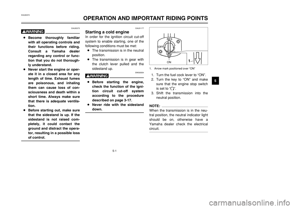
1. Turn the fuel cock lever to “ON”.
2. Turn the key to “ON” and make
sure that the engine stop switch
is set to “#”.
3. Shift the transmission into the
neutral position.NOTE:
When the transmission is in the neu-
tral position, the neutral indicator light
should be on, otherwise have a
Yamaha dealer check the electrical
circuit.
ON
FUEL
RES
OFF
1
ON
1. Arrow mark positioned over “ON”
3MB-9-E8 6/13/01 10:55 AM Page 33
Page 35 of 96
5-2
OPERATION AND IMPORTANT RIDING POINTS
54. Turn the starter (choke) on and
completely close the throttle.
(See page 3-10 for starter
(choke) operation.)
5. Start the engine by pushing the
kickstarter lever down.
6. After starting the engine, move
the starter (choke) lever back
halfway.
ECA00045
cCFor maximum engine life, never
accelerate hard when the engine is
cold!7. When the engine is warm, turn
the starter (choke) off.NOTE:
The engine is warm when it responds
normally to the throttle with the starter
(choke) turned off.
EAU01258
Starting a warm engineFollow the same procedure as for
starting a cold engine with the excep-
tion that the starter (choke) is not
required when the engine is warm.
EAU00423
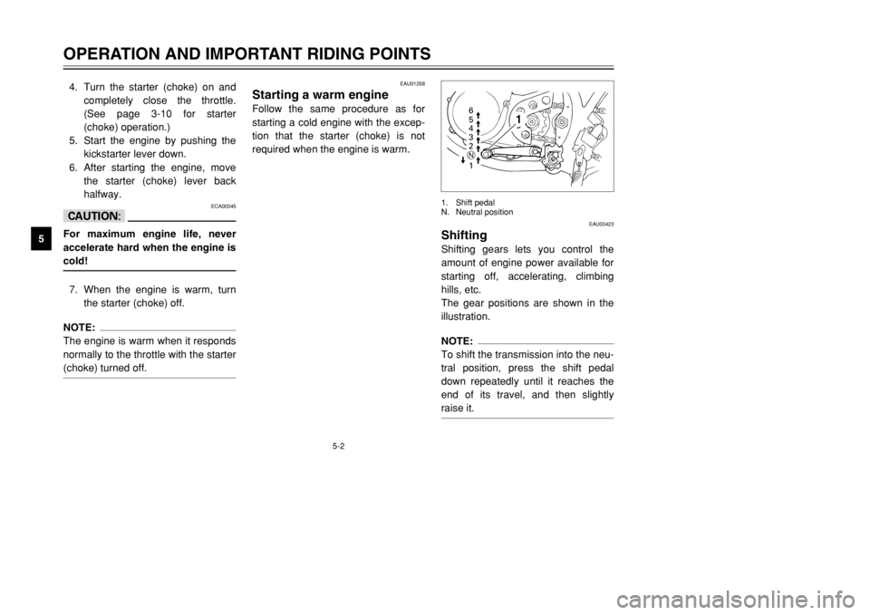
ShiftingShifting gears lets you control the
amount of engine power available for
starting off, accelerating, climbing
hills, etc.
The gear positions are shown in the
illustration.NOTE:
To shift the transmission into the neu-
tral position, press the shift pedal
down repeatedly until it reaches the
end of its travel, and then slightly
raise it.
6
5
4
3
2
1 N
1
1. Shift pedal
N. Neutral position
3MB-9-E8 6/13/01 10:55 AM Page 34
Page 36 of 96

5-3
OPERATION AND IMPORTANT RIDING POINTS
5
EC000048
cC8Even with the transmission in
the neutral position, do not
coast for long periods of time
with the engine off, and do not
tow the motorcycle for long
distances. The transmission is
properly lubricated only when
the engine is running.
Inadequate lubrication may
damage the transmission.
8Always use the clutch while
changing gears to avoid dam-
aging the engine, transmis-
sion, and drive train, which are
not designed to withstand the
shock of forced shifting.
EAU02937
Recommended shift points
(for Switzerland only)The recommended shift points during
acceleration are shown in the table
below.NOTE:
When shifting down two gears at a
time, reduce the speed accordingly
(e.g., down to 35 km/h when shifting
from 5th to 3rd gear).
EAU00424
Tips for reducing fuel
consumptionFuel consumption depends largely on
your riding style. Consider the follow-
ing tips to reduce fuel consumption:
8Thoroughly warm up the engine.
8Turn the starter (choke) off as
soon as possible.
8Shift up swiftly, and avoid high
engine speeds during accelera-
tion.
8Do not rev the engine while shift-
ing down, and avoid high engine
speeds with no load on the
engine.
8Turn the engine off instead of let-
ting it idle for an extended length
of time (e.g., in traffic jams, at
traffic lights or at railroad cross-
ings).
Shift point
(km/h)
1st→2nd
2nd→3rd
3rd→4th
4th→5th
5th→6th20
30
40
50
60
3MB-9-E8 6/13/01 10:55 AM Page 35