clock YAMAHA DT125R 2002 Owners Manual
[x] Cancel search | Manufacturer: YAMAHA, Model Year: 2002, Model line: DT125R, Model: YAMAHA DT125R 2002Pages: 96, PDF Size: 2.14 MB
Page 18 of 96
3-5
INSTRUMENT AND CONTROL FUNCTIONS
3
EAU00158
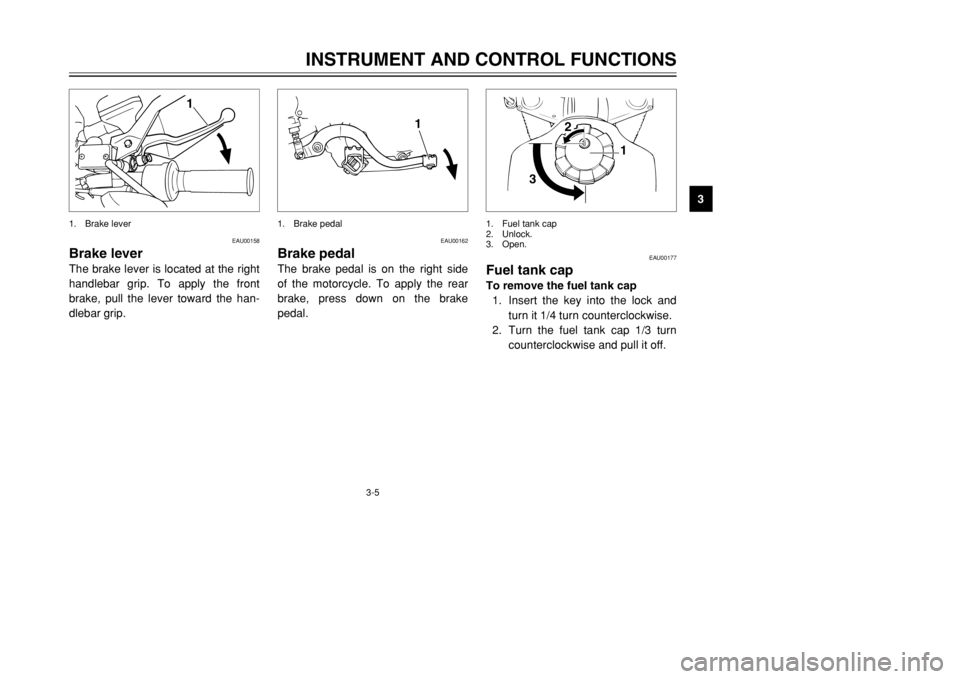
Brake leverThe brake lever is located at the right
handlebar grip. To apply the front
brake, pull the lever toward the han-
dlebar grip.
1
1. Brake lever
EAU00162
Brake pedalThe brake pedal is on the right side
of the motorcycle. To apply the rear
brake, press down on the brake
pedal.
1
1. Brake pedal
EAU00177
Fuel tank capTo remove the fuel tank cap
1. Insert the key into the lock and
turn it 1/4 turn counterclockwise.
2. Turn the fuel tank cap 1/3 turn
counterclockwise and pull it off.
31
2
1. Fuel tank cap
2. Unlock.
3. Open.
3MB-9-E8 6/13/01 10:55 AM Page 17
Page 19 of 96
3-6
INSTRUMENT AND CONTROL FUNCTIONS
3To install the fuel tank cap
1. Insert the fuel tank cap into the
tank opening with the key insert-
ed in the lock, and then turn the
cap 1/3 turn clockwise.
2. Turn the key 1/4 turn clockwise,
and then remove it.
NOTE:
The fuel tank cap cannot be installed
unless the key is in the lock. In addi-
tion, the key cannot be removed if the
cap is not properly installed and
locked.
EW000023
wMake sure that the fuel tank cap is
properly closed and locked before
riding.
EAU03753
Fuel(except for Switzerland and
Austria)
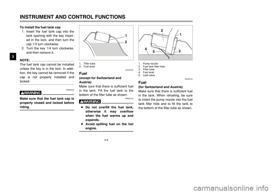
Make sure that there is sufficient fuel
in the tank. Fill the fuel tank to the
bottom of the filler tube as shown.
EW000130
w8Do not overfill the fuel tank,
otherwise it may overflow
when the fuel warms up and
expands.
8Avoid spilling fuel on the hot
engine.
21
1. Filler tube
2. Fuel level
EAU03754
Fuel(for Switzerland and Austria)
Make sure that there is sufficient fuel
in the tank. When refueling, be sure
to insert the pump nozzle into the fuel
tank filler hole and to fill the tank to
the bottom of the filler tube as shown.
1
3
5 42
1. Pump nozzle
2. Fuel tank filler hole
3. Filler tube
4. Fuel level
5. Leaf valve
3MB-9-E8 6/13/01 10:55 AM Page 18
Page 23 of 96
3-10
INSTRUMENT AND CONTROL FUNCTIONS
3
EAU03839
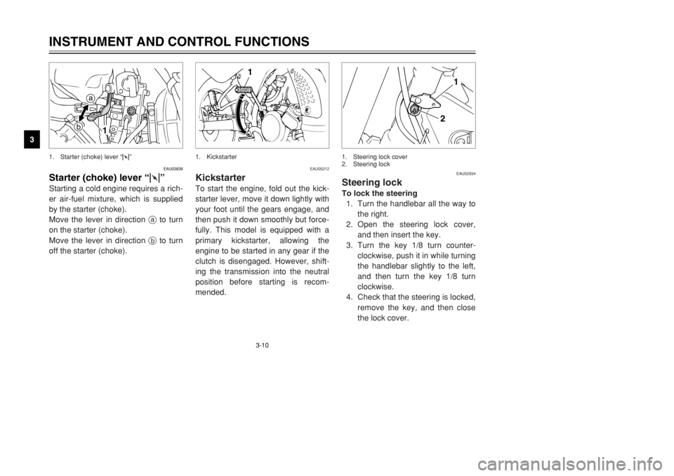
Starter (choke) lever“1”Starting a cold engine requires a rich-
er air-fuel mixture, which is supplied
by the starter (choke).
Move the lever in direction ato turn
on the starter (choke).
Move the lever in direction bto turn
off the starter (choke).
a
b
1
1. Starter (choke) lever “1”
EAU00212
KickstarterTo start the engine, fold out the kick-
starter lever, move it down lightly with
your foot until the gears engage, and
then push it down smoothly but force-
fully. This model is equipped with a
primary kickstarter, allowing the
engine to be started in any gear if the
clutch is disengaged. However, shift-
ing the transmission into the neutral
position before starting is recom-
mended.
1
1. Kickstarter
EAU02934
Steering lockTo lock the steering
1. Turn the handlebar all the way to
the right.
2. Open the steering lock cover,
and then insert the key.
3. Turn the key 1/8 turn counter-
clockwise, push it in while turning
the handlebar slightly to the left,
and then turn the key 1/8 turn
clockwise.
4. Check that the steering is locked,
remove the key, and then close
the lock cover.
2
1
1. Steering lock cover
2. Steering lock
3MB-9-E8 6/13/01 10:55 AM Page 22
Page 24 of 96
3-11
INSTRUMENT AND CONTROL FUNCTIONS
3 To unlock the steering
1. Open the steering lock cover,
and then insert the key.
2. Push the key in, turn it 1/8 turn
counterclockwise so that it
moves out, and then release it.
3. Remove the key, and then close
the lock cover.
EAU01648
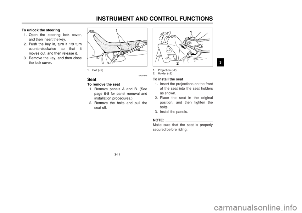
SeatTo remove the seat
1. Remove panels A and B. (See
page 6-8 for panel removal and
installation procedures.)
2. Remove the bolts and pull the
seat off.
1
1. Bolt (
×2)
To install the seat
1. Insert the projections on the front
of the seat into the seat holders
as shown.
2. Place the seat in the original
position, and then tighten the
bolts.
3. Install the panels.NOTE:
Make sure that the seat is properly
secured before riding.
1
2
1. Projection (×2)
2. Holder (×2)
3MB-9-E8 6/13/01 10:55 AM Page 23
Page 74 of 96
6-36
PERIODIC MAINTENANCE AND MINOR REPAIR
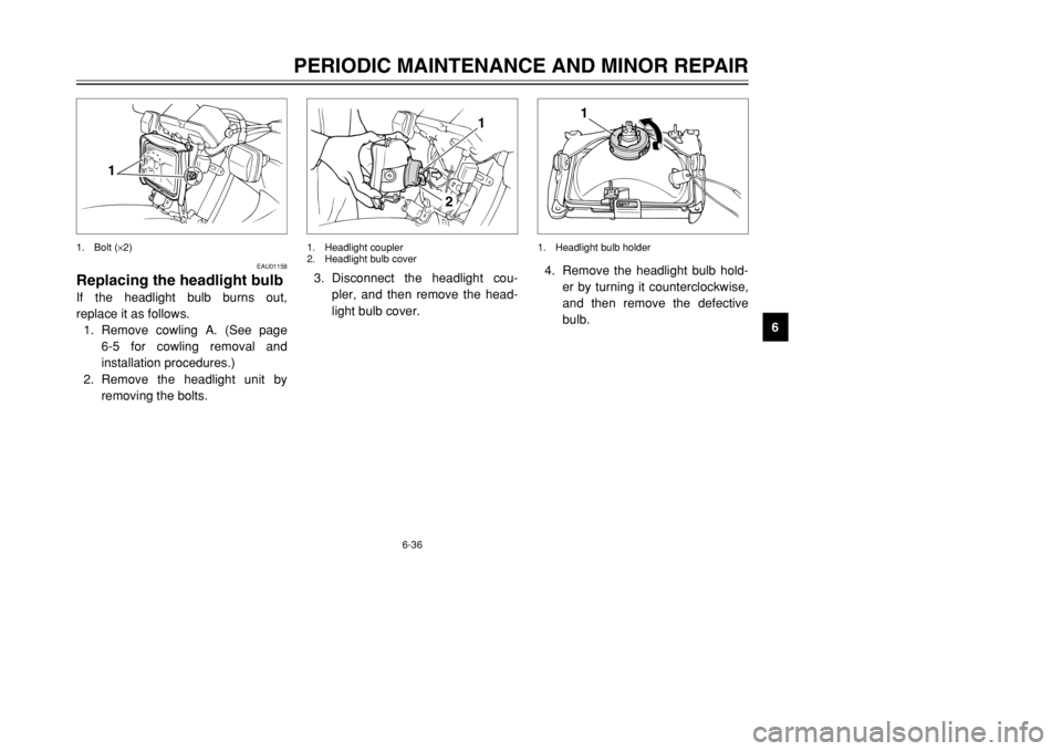
6 4. Remove the headlight bulb hold-
er by turning it counterclockwise,
and then remove the defective
bulb.
1
1. Headlight bulb holder
3. Disconnect the headlight cou-
pler, and then remove the head-
light bulb cover.
1
2
1. Headlight coupler
2. Headlight bulb cover
EAU01158
Replacing the headlight bulbIf the headlight bulb burns out,
replace it as follows.
1. Remove cowling A. (See page
6-5 for cowling removal and
installation procedures.)
2. Remove the headlight unit by
removing the bolts.
1
1. Bolt (×2)
3MB-9-E8 6/13/01 10:55 AM Page 73
Page 75 of 96
6-37
PERIODIC MAINTENANCE AND MINOR REPAIR
6
EAU03497
Replacing a turn signal light
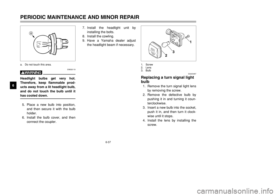
bulb1. Remove the turn signal light lens
by removing the screw.
2. Remove the defective bulb by
pushing it in and turning it coun-
terclockwise.
3. Insert a new bulb into the socket,
push it in, and then turn it clock-
wise until it stops.
4. Install the lens by installing the
screw.
1
2
3
1. Screw
2. Lens
3. Bulb
7. Install the headlight unit by
installing the bolts.
8. Install the cowling.
9. Have a Yamaha dealer adjust
the headlight beam if necessary.
EW000119
wHeadlight bulbs get very hot.
Therefore, keep flammable prod-
ucts away from a lit headlight bulb,
and do not touch the bulb until it
has cooled down.5. Place a new bulb into position,
and then secure it with the bulb
holder.
6. Install the bulb cover, and then
connect the coupler.
a
a. Do not touch this area.
3MB-9-E8 6/13/01 10:55 AM Page 74
Page 76 of 96
6-38
PERIODIC MAINTENANCE AND MINOR REPAIR
6
EC000108
cCDo not overtighten the screws,
otherwise the lens may break.
EAU01623
Replacing the tail/brake light
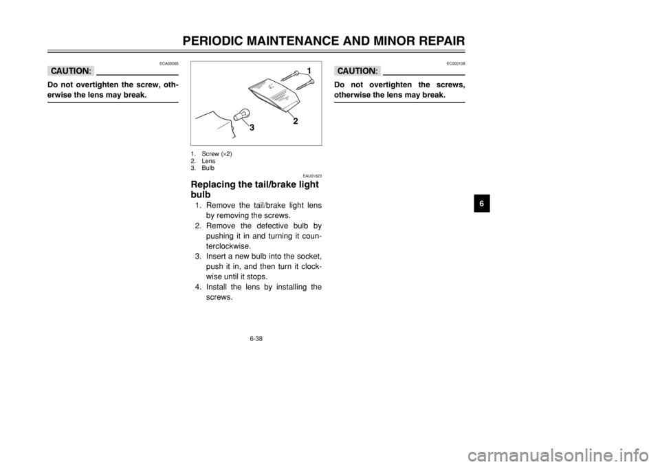
bulb1. Remove the tail/brake light lens
by removing the screws.
2. Remove the defective bulb by
pushing it in and turning it coun-
terclockwise.
3. Insert a new bulb into the socket,
push it in, and then turn it clock-
wise until it stops.
4. Install the lens by installing the
screws.
1
2
3
1. Screw (×2)
2. Lens
3. Bulb
ECA00065
cCDo not overtighten the screw, oth-
erwise the lens may break.
3MB-9-E8 6/13/01 10:55 AM Page 75
Page 83 of 96

6-45
PERIODIC MAINTENANCE AND MINOR REPAIR
6
Wait until the
Check the coolant level in the
Level is OK.Level is low, check the
NoLeakage.
Ask a Yamaha dealer to inspectAdd coolant. (See NOTE.)
Restart the engine. If the engine overheats again, ask a
engine has cooled.reservoir tank and/or radiator.cooling system for leakage.
Yamaha dealer to inspect and repair the cooling system.leakage.
and repair the cooling system.
4. Engine overheating
EW000070
w8Do not remove the radiator cap when the engine and radiator are hot. Scalding hot fluid and steam may be
blown out under pressure, which could cause serious injury. Be sure to wait until the engine has cooled.
8After removing the radiator cap retaining bolt, place a thick rag, like a towel, over the radiator cap, and then
slowly rotate the cap counterclockwise to the detent to allow any residual pressure to escape. When the
hissing sound has stopped, press down on the cap while turning it counterclockwise, and then remove the
cap.NOTE:
If it is difficult to get the recommended coolant, tap water can be temporarily used, provided that it is changed to the rec-
ommended coolant as soon as possible.
3MB-9-E8 6/13/01 10:55 AM Page 82