display YAMAHA EC-03 2011 Owners Manual
[x] Cancel search | Manufacturer: YAMAHA, Model Year: 2011, Model line: EC-03, Model: YAMAHA EC-03 2011Pages: 78, PDF Size: 2.04 MB
Page 6 of 78
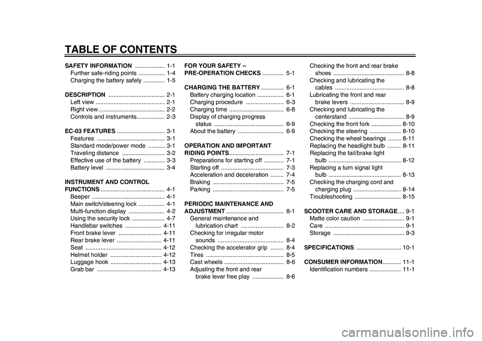
TABLE OF CONTENTSSAFETY INFORMATION .................. 1-1
Further safe-riding points ................ 1-4
Charging the battery safely ............. 1-5
DESCRIPTION .................................. 2-1
Left view .......................................... 2-1
Right view ........................................ 2-2
Controls and instruments................. 2-3
EC-03 FEATURES............................. 3-1
Features ......................................... 3-1
Standard mode/power mode .......... 3-1
Traveling distance .......................... 3-2
Effective use of the battery ............. 3-3
Battery level .................................... 3-4
INSTRUMENT AND CONTROL
FUNCTIONS....................................... 4-1
Beeper ............................................ 4-1
Main switch/steering lock ................ 4-1
Multi-function display ...................... 4-2
Using the security lock .................... 4-7
Handlebar switches ...................... 4-11
Front brake lever .......................... 4-11
Rear brake lever ........................... 4-11
Seat .............................................. 4-12
Helmet holder ............................... 4-12
Luggage hook ............................... 4-13
Grab bar ....................................... 4-13FOR YOUR SAFETY –
PRE-OPERATION CHECKS............. 5-1
CHARGING THE BATTERY.............. 6-1
Battery charging location ................ 6-1
Charging procedure ....................... 6-3
Charging time ................................. 6-8
Display of charging progress
status .......................................... 6-9
About the battery ............................ 6-9
OPERATION AND IMPORTANT
RIDING POINTS................................. 7-1
Preparations for starting off ............ 7-1
Starting off ...................................... 7-3
Acceleration and deceleration ........ 7-4
Braking ........................................... 7-5
Parking ........................................... 7-5
PERIODIC MAINTENANCE AND
ADJUSTMENT................................... 8-1
General maintenance and
lubrication chart .......................... 8-2
Checking for irregular motor
sounds ........................................ 8-4
Checking the accelerator grip ........ 8-4
Tires ............................................... 8-5
Cast wheels .................................... 8-6
Adjusting the front and rear
brake lever free play ................... 8-6Checking the front and rear brake
shoes ........................................... 8-8
Checking and lubricating the
cables .......................................... 8-8
Lubricating the front and rear
brake levers ................................. 8-9
Checking and lubricating the
centerstand .................................. 8-9
Checking the front fork .................. 8-10
Checking the steering ................... 8-10
Checking the wheel bearings ........ 8-11
Replacing the headlight bulb ........ 8-11
Replacing the tail/brake light
bulb ............................................ 8-12
Replacing a turn signal light
bulb ............................................ 8-13
Checking the charging cord and
charging plug ............................. 8-14
Troubleshooting ............................ 8-15
SCOOTER CARE AND STORAGE.... 9-1
Matte color caution ......................... 9-1
Care ................................................ 9-1
Storage ........................................... 9-3
SPECIFICATIONS ........................... 10-1
CONSUMER INFORMATION........... 11-1
Identification numbers ................... 11-11CB-9-E0.book 1 ページ 2010年10月15日 金曜日 午前10時19分
Page 14 of 78
DESCRIPTION
2-3
12
3
4
5
6
7
8
9
EAU10430
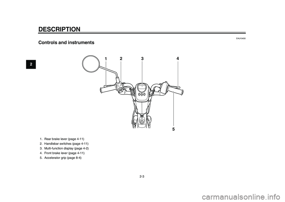
Controls and instruments
124
5
3
1. Rear brake lever (page 4-11)
2. Handlebar switches (page 4-11)
3. Multi-function display (page 4-2)
4. Front brake lever (page 4-11)
5. Accelerator grip (page 8-4)
1CB-9-E0.book 3 ページ 2010年10月15日 金曜日 午前10時19分
Page 15 of 78
3-1
234
5
6
7
8
9
EC-03 FEATURES
EAU50470
Features The features of the EC-03 are follow-
ing:
The driving power source is only
electricity and there is no need for
fuel supply or engine oil change.
High performance motor with
greatly reduced noise and vibra-
tion providing a pleasant ride.
Charging the vehicle can be done
via a grounded electrical outlet
with residual-current device (RCD)
protection.
EAU50322
Standard mode/power mode The motor driving power can be select-
ed according to riding conditions, road
conditions, etc.
The standard mode is suitable for nor-
mal riding, while the power mode pro-
vides more comfortable riding when
ascending hills.
Switching the mode
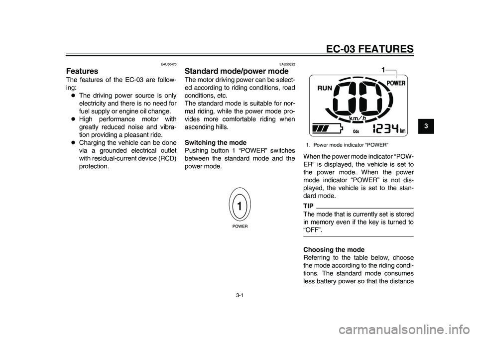
Pushing button 1 “POWER” switches
between the standard mode and the
power mode.When the power mode indicator “POW-
ER” is displayed, the vehicle is set to
the power mode. When the power
mode indicator “POWER” is not dis-
played, the vehicle is set to the stan-
dard mode.
TIPThe mode that is currently set is stored
in memory even if the key is turned to“OFF”.
Choosing the mode
Referring to the table below, choose
the mode according to the riding condi-
tions. The standard mode consumes
less battery power so that the distance1. Power mode indicator “POWER”
1
1CB-9-E0.book 1 ページ 2010年10月15日 金曜日 午前10時19分
Page 19 of 78
EC-03 FEATURES
3-5
234
5
6
7
8
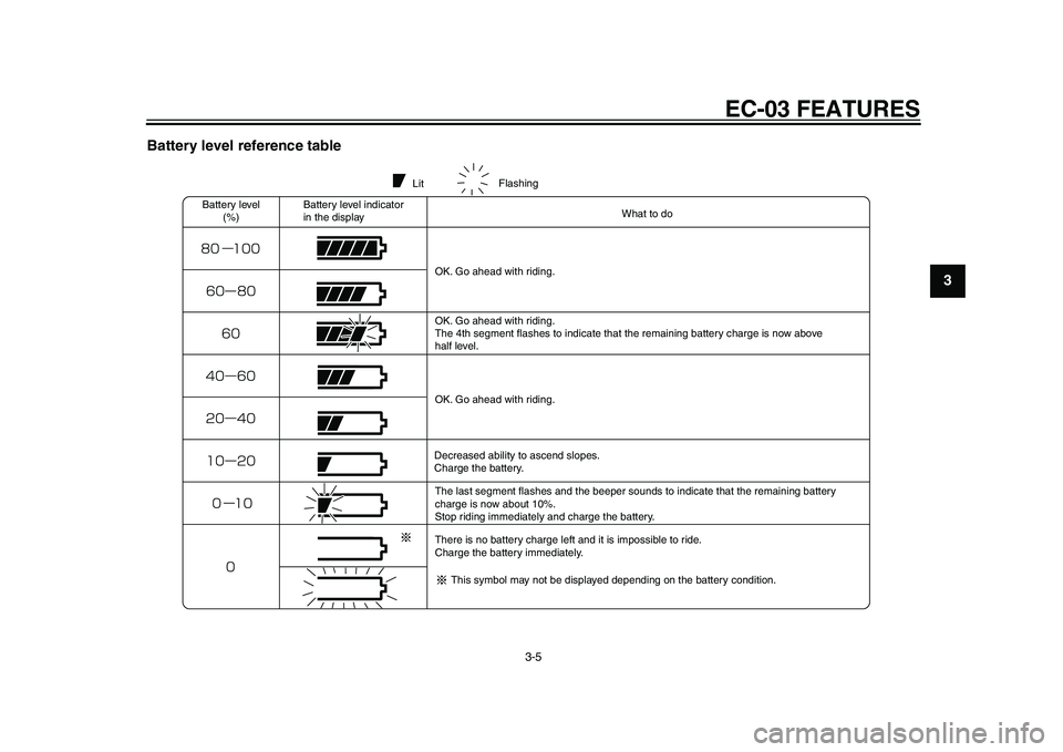
9 Battery level reference table
LitFlashing
Battery level
(%)Battery level indicator
in the displayWhat to do
OK. Go ahead with riding.
OK. Go ahead with riding.
The 4th segment flashes to indicate that the remaining battery charge is now above
half level.
OK. Go ahead with riding.
Decreased ability to ascend slopes.
Charge the battery.
The last segment flashes and the beeper sounds to indicate that the remaining battery
charge is now about 10%.
Stop riding immediately and charge the battery.
There is no battery charge left and it is impossible to ride.
Charge the battery immediately.
This symbol may not be displayed depending on the battery condition.
1CB-9-E0.book 5 ページ 2010年10月15日 金曜日 午前10時19分
Page 21 of 78
INSTRUMENT AND CONTROL FUNCTIONS
4-2
2
345
6
7
8
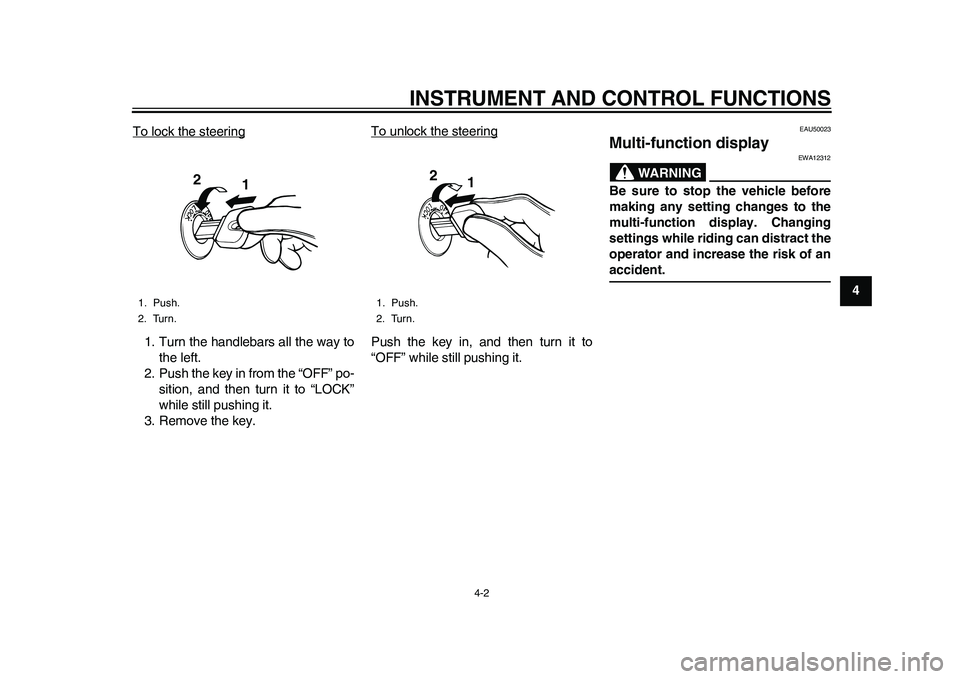
9 To lock the steering
1. Turn the handlebars all the way to
the left.
2. Push the key in from the “OFF” po-
sition, and then turn it to “LOCK”
while still pushing it.
3. Remove the key.To unlock the steering
Push the key in, and then turn it to
“OFF” while still pushing it.
EAU50023
Multi-function display
WARNING
EWA12312
Be sure to stop the vehicle before
making any setting changes to the
multi-function display. Changing
settings while riding can distract the
operator and increase the risk of anaccident.
1. Push.
2. Turn.
1
2
1. Push.
2. Turn.
1 2
1CB-9-E0.book 2 ページ 2010年10月15日 金曜日 午前10時19分
Page 22 of 78
INSTRUMENT AND CONTROL FUNCTIONS
4-3
1
2
34
5
6
7
8
9
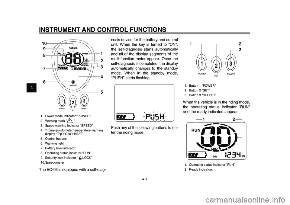
The EC-03 is equipped with a self-diag-nosis device for the battery and control
unit. When the key is turned to “ON”,
the self-diagnosis starts automatically
and all of the display segments of the
multi-function meter appear. Once the
self-diagnosis is completed, the display
automatically changes to the standby
mode. When in the standby mode,
“PUSH” starts flashing.
Push any of the following buttons to en-
ter the riding mode.When the vehicle is in the riding mode,
the operating status indicator “RUN”
and the ready indicators appear.
1. Power mode indicator “POWER”
2. Warning mark “ ”
3. Speed warning indicator “SPEED”
4. Tripmeter/odometer/temperature warning
display “Trip”/“Odo”/“HEAT”
5. Control buttons
6. Warning light
7. Battery level indicator
8. Operating status indicator “RUN”
9. Security lock indicator “ LOCK”
10.Speedometer
1
2
3
4
5 6 7 8 9 10
1. Button 1 “POWER”
2. Button 2 “SET”
3. Button 3 “SELECT”
1. Operating status indicator “RUN”
2. Ready indicators
12
3
12
1CB-9-E0.book 3 ページ 2010年10月15日 金曜日 午前10時19分
Page 23 of 78
INSTRUMENT AND CONTROL FUNCTIONS
4-4
2
345
6
7
8
9
TIPWhen the vehicle is in the riding mode,
the beeper sounds. The beeper stops
when either brake lever is squeezed orthe vehicle starts moving.
Control buttons
Button 1 “POWER”
Button 2 “SET”
Button 3 “SELECT”
The following operations and settings
are made using these buttons.
Changing from the standby mode
to the riding mode
Switching between the standard
mode and the power mode
Switching between the odometer
and the tripmeter
Resetting the tripmeter
Registering or changing the secu-
rity number
Locking and unlocking the security
lock
Speedometer
The speedometer shows the riding
speed.Tripmeter “Trip”
The tripmeter shows the distance trav-
eled since it was last set to zero. To re-
set the tripmeter, push and hold button
3 “SELECT” for a few seconds until
“0.0” is displayed.
Odometer “Odo”
Push button 3 “SELECT” for at least
one second to switch the display to the
odometer.
The odometer shows the total distance
traveled. Use the odometer as a refer-
ence for the intervals between perform-
ing periodic maintenance.
Push button 3 for at least one second to
switch the display to the tripmeter.
Temperature warning display
“HEAT”/“COOL”
The EC-03 is equipped with a tempera-
ture protection function to protect the
battery and control unit.
If a problem is detected, the tripmeter/
odometer display is canceled and
“COOL” or “HEAT” flash.
When the temperature of the bat-
tery or control unit exceeds a spec-
ified temperature, “HEAT” flashes.
When the temperature of the bat-
tery falls below a specified temper-
ature, “COOL” flashes.
TIP
When the temperature of the bat-
tery exceeds a specified tempera-
ture, “HEAT” flashes and the
driving power is reduced to limit
the electric output from the battery,
but this is normal.
When the temperature of the bat-
tery falls below a specified temper-
ature, “COOL” flashes and the
driving power is reduced to limit
the electric output from the battery,
but this is normal.
If the vehicle is ridden for an ex-
tended period in high tempera-
tures, “HEAT” may flash and the
riding speed may be reduced.
If the vehicle is ridden after it has
been left in a hot place or under di-
rect sunlight, “HEAT” may flash
and the riding speed may be re-
duced.
If the vehicle is ridden after it has
been left in an excessively cold
place (less than 0 C), “COOL”
1CB-9-E0.book 4 ページ 2010年10月15日 金曜日 午前10時19分
Page 24 of 78
INSTRUMENT AND CONTROL FUNCTIONS
4-5
1
2
34
5
6
7
8
9may flash and the riding speed
may be reduced.
When the battery level indicator
shows less than two segments, if
the vehicle is exposed to higher
temperatures, “COOL” may flash
and the riding speed may be re-
duced.
When riding on a long uphill
stretch, “HEAT” may flash and the
riding speed may be reduced.
When riding on a long uphill
stretch, the temperature of the
control unit may rise and “HEAT”
may flash. If you ride continually,
the operating status indicator
“RUN” goes off to protect the con-
trol unit and further riding may be
impossible, but this is not a mal-function.
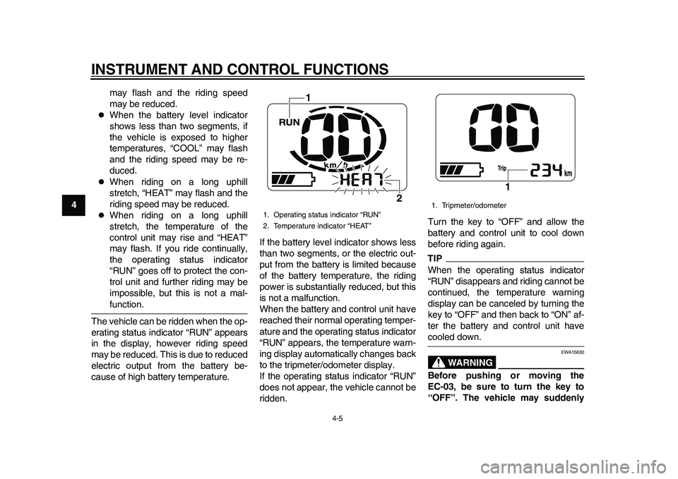
The vehicle can be ridden when the op-
erating status indicator “RUN” appears
in the display, however riding speed
may be reduced. This is due to reduced
electric output from the battery be-
cause of high battery temperature.If the battery level indicator shows less
than two segments, or the electric out-
put from the battery is limited because
of the battery temperature, the riding
power is substantially reduced, but this
is not a malfunction.
When the battery and control unit have
reached their normal operating temper-
ature and the operating status indicator
“RUN” appears, the temperature warn-
ing display automatically changes back
to the tripmeter/odometer display.
If the operating status indicator “RUN”
does not appear, the vehicle cannot be
ridden.Turn the key to “OFF” and allow the
battery and control unit to cool down
before riding again.
TIPWhen the operating status indicator
“RUN” disappears and riding cannot be
continued, the temperature warning
display can be canceled by turning the
key to “OFF” and then back to “ON” af-
ter the battery and control unit havecooled down.
WARNING
EWA15630
Before pushing or moving the
EC-03, be sure to turn the key to
“OFF”. The vehicle may suddenly
1. Operating status indicator “RUN”
2. Temperature indicator “HEAT”
1
2
1. Tripmeter/odometer
1
1CB-9-E0.book 5 ページ 2010年10月15日 金曜日 午前10時19分
Page 25 of 78
INSTRUMENT AND CONTROL FUNCTIONS
4-6
2
345
6
7
8
9 start to move if the accelerator grip
is turned while the key is turned to
“ON”.
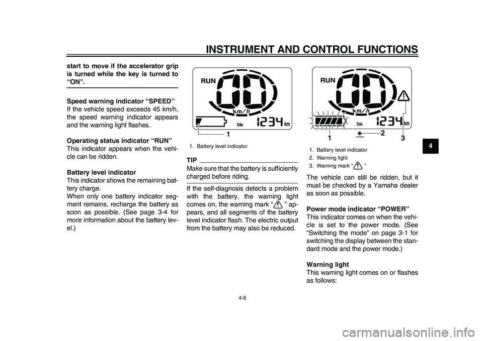
Speed warning indicator “SPEED”
If the vehicle speed exceeds 45 km/h,
the speed warning indicator appears
and the warning light flashes.
Operating status indicator “RUN”
This indicator appears when the vehi-
cle can be ridden.
Battery level indicator
This indicator shows the remaining bat-
tery charge.
When only one battery indicator seg-
ment remains, recharge the battery as
soon as possible. (See page 3-4 for
more information about the battery lev-
el.)
TIPMake sure that the battery is sufficientlycharged before riding.
If the self-diagnosis detects a problem
with the battery, the warning light
comes on, the warning mark “ ” ap-
pears, and all segments of the battery
level indicator flash. The electric output
from the battery may also be reduced.The vehicle can still be ridden, but it
must be checked by a Yamaha dealer
as soon as possible.
Power mode indicator “POWER”
This indicator comes on when the vehi-
cle is set to the power mode. (See
“Switching the mode” on page 3-1 for
switching the display between the stan-
dard mode and the power mode.)
Warning light
This warning light comes on or flashes
as follows:1. Battery level indicator
1
1. Battery level indicator
2. Warning light
3. Warning mark “ ”
2
1
3
1CB-9-E0.book 6 ページ 2010年10月15日 金曜日 午前10時19分
Page 26 of 78
INSTRUMENT AND CONTROL FUNCTIONS
4-7
1
2
34
5
6
7
8
9Speed warning indicator
The warning light flashes when vehicle
speed exceeds 45 km/h. At the same
time, the speed warning indicator
“SPEED” appears.
Error warningsIf a problem is detected, the warning
light comes on. In this case, check for
the warning mark “ ”. If this warning
mark also appears, have a Yamaha
dealer check the vehicle.
Warning mark “ ”
This warning mark flashes if a problem
is detected. If the warning mark keeps
flashing after turning the key to “OFF”
and then back to “ON”, have a Yamaha
dealer check the vehicle.TIPAfter turning the key to “ON”, the warn-
ing mark appears. If the warning mark
goes out after a few seconds, there isno malfunction. Go ahead with riding.
EAU50033
Using the security lock The EC-03 is equipped with a security
lock that can be used by registering a
security number. Once the security
number has been set, the vehicle can-
not be ridden unless the correct securi-
ty number is entered, even if the key is
turned to “ON”.
Registering and changing the secu-
rity number
WARNING
EWA15610
Be sure to stop the vehicle before
registering or changing the security
number. Changing settings while
riding can distract the operator andincrease the risk of an accident.TIPThe security number registration/
change mode is canceled if the regis-
tering procedure is not completed in
one minute. If the mode cancels, repeatthe procedure.
1. Turn the key to “ON”.
All display segments appear for a
few seconds, then the vehicle en-ters the standby mode and
“PUSH” flashes.
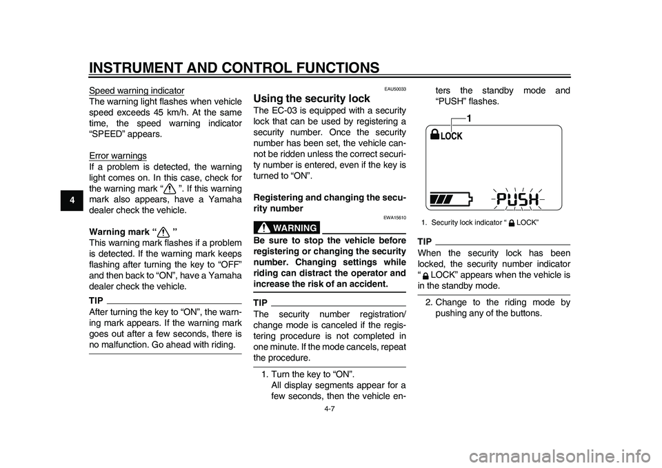
TIPWhen the security lock has been
locked, the security number indicator
“ LOCK” appears when the vehicle isin the standby mode.
2. Change to the riding mode by
pushing any of the buttons.1. Security lock indicator “ LOCK”
1
1CB-9-E0.book 7 ページ 2010年10月15日 金曜日 午前10時19分