YAMAHA GRIZZLY 660 2003 Owners Manual
GRIZZLY 660 2003
YAMAHA
YAMAHA
https://www.carmanualsonline.info/img/51/50435/w960_50435-0.png
YAMAHA GRIZZLY 660 2003 Owners Manual
Trending: fuel cap, ESP, odometer, carb, coolant capacity, oil filter, octane
Page 281 of 442
8-16
FBU00614
Dépose et mise en place des caches
Il faudra déposer les caches illustrés pour effectuer cer-
tains des entretiens décrits dans ce chapitre.
Se référer à cette section à chaque fois qu’il faut déposer
ou mettre en place un cache.
SBU00614
Extracción e instalación de los paneles
Los paneles indicados deben extraerse para efec-
tuar algunas de las tareas de mantenimiento descri-
bas en este capítulo.
Consulte esta sección cada vez que deba extraer/
instalar un panel.
U5KM60.book Page 16 Thursday, June 21, 2001 2:40 PM
Page 282 of 442
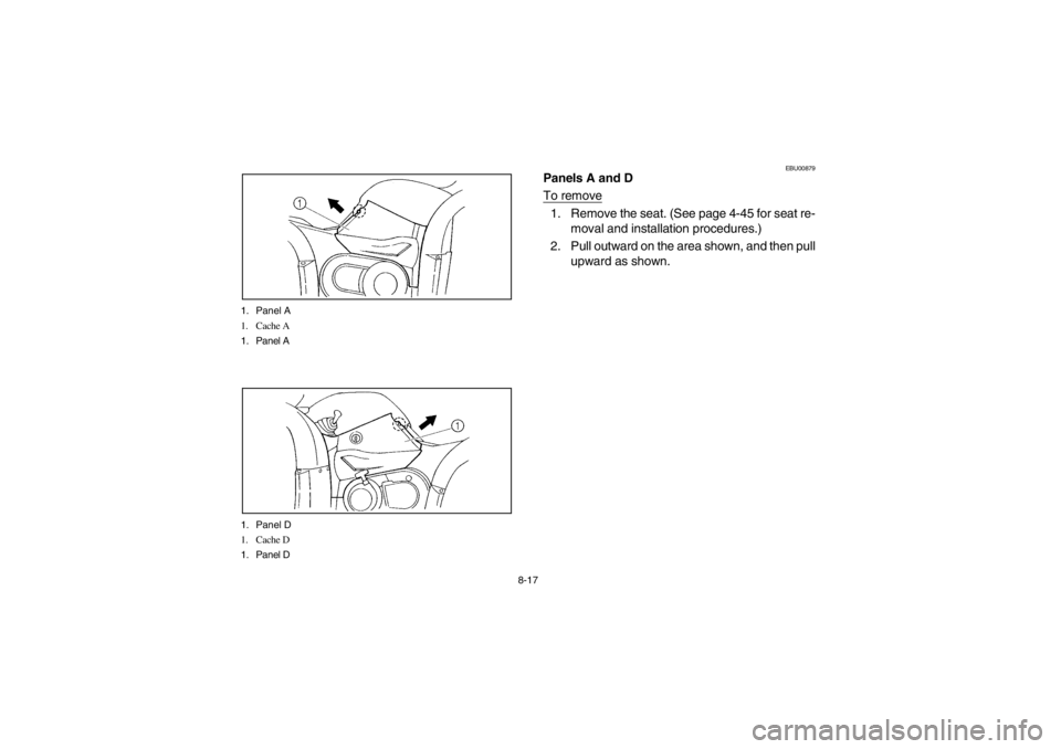
8-17 1. Panel A
1. Cache A
1. Panel A
1. Panel D
1. Cache D
1. Panel D
EBU00879
Panels A and D
To remove1. Remove the seat. (See page 4-45 for seat re-
moval and installation procedures.)
2. Pull outward on the area shown, and then pull
upward as shown.
U5KM60.book Page 17 Thursday, June 21, 2001 2:40 PM
Page 283 of 442
8-18
FBU00879
Caches A et D
Dépose1. Déposer la selle. (Voir les explications relatives à
la dépose et à la mise en place de la selle à la page
4-46.)
2. Tirer vers l’arrière à l’endroit indiqué, puis tirer
vers le haut.
SBU00879
Paneles A y D
Para la extracción1. Extraiga el asiento. (Para ver los procedimien-
tos de extracción e instalación del asiento, con-
sulte la página 4-46.)
2. Tire hacia fuera por la parte indicada, y enton-
ces tire hacia arriba como se muestra.
U5KM60.book Page 18 Thursday, June 21, 2001 2:40 PM
Page 284 of 442
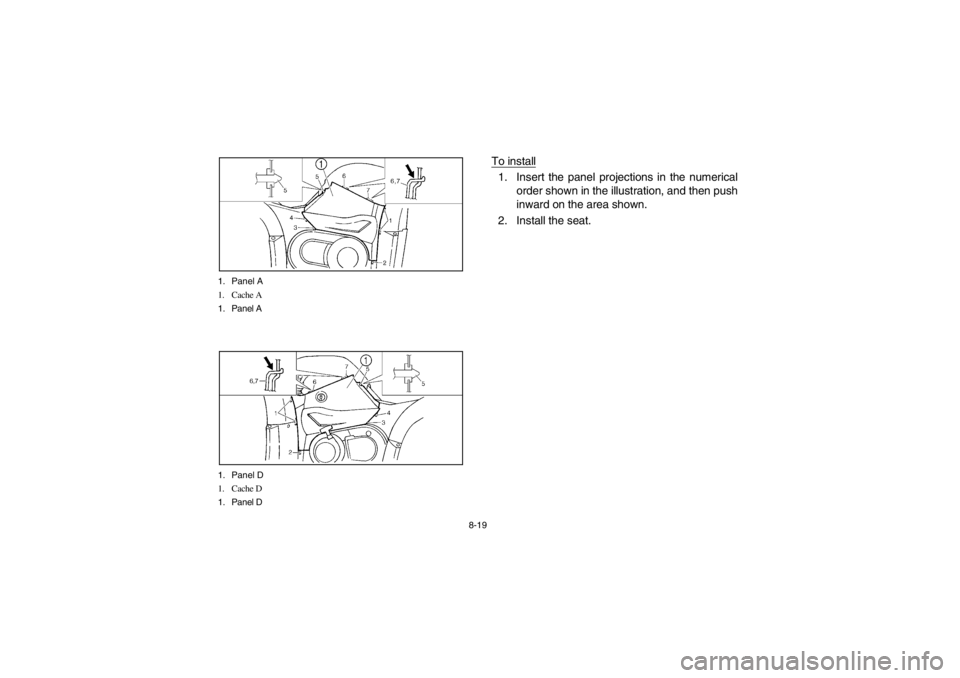
8-19 1. Panel A
1. Cache A
1. Panel A
1. Panel D
1. Cache D
1. Panel D
To install1. Insert the panel projections in the numerical
order shown in the illustration, and then push
inward on the area shown.
2. Install the seat.
U5KM60.book Page 19 Thursday, June 21, 2001 2:40 PM
Page 285 of 442
8-20
Mise en place1. Insérer les saillies du cache dans l’ordre numérique
figurant dans l’illustration, puis appuyer à l’endroit
indiqué.
2. Remettre la selle en place. Para la instalación
1. Inserte los salientes del panel siguiendo el or-
den numérico mostrado en la ilustración, y en-
tonces empuje hacia dentro la parte mostrada.
2. Vuelva a instalar el asiento.
U5KM60.book Page 20 Thursday, June 21, 2001 2:40 PM
Page 286 of 442
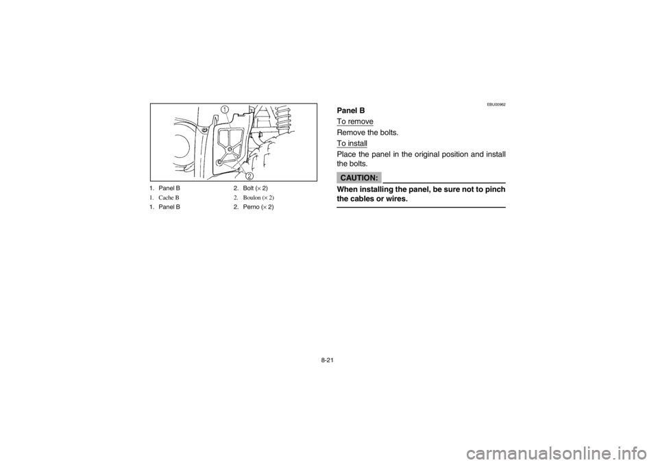
8-21 1. Panel B 2. Bolt (× 2)
1. Cache B 2. Boulon (× 2)
1. Panel B 2. Perno (× 2)
EBU00962
Panel B
To removeRemove the bolts.
To installPlace the panel in the original position and install
the bolts.CAUTION:_ When installing the panel, be sure not to pinch
the cables or wires. _
U5KM60.book Page 21 Thursday, June 21, 2001 2:40 PM
Page 287 of 442
8-22
FBU00962
Cache B
DéposeRetirer les boulons.
Mise en placeRemettre le cache à sa place, puis monter les boulons.ATTENTION:_ En remettant le cache en place, bien veiller à ne pas
pincer les câbles ou les fils. _
SBU00962
Panel B
Para extraerloExtraiga los pernos.
Para instalarloColoque el panel en su posición original e instale los
pernos.AT E N C I O N :_ Cuando instale el panel, asegúrese de no pelliz-
car los cables ni los conductores. _
U5KM60.book Page 22 Thursday, June 21, 2001 2:40 PM
Page 288 of 442
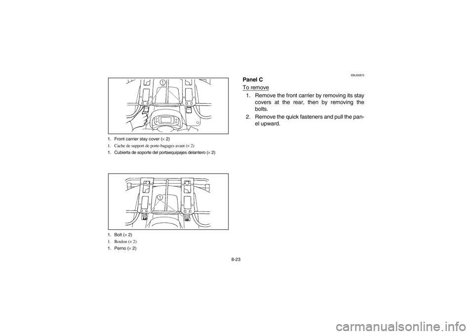
8-23 1. Front carrier stay cover (× 2)
1. Cache de support de porte-bagages avant (× 2)
1. Cubierta de soporte del portaequipajes delantero (× 2)
1. Bolt (× 2)
1. Boulon (× 2)
1. Perno (× 2)
EBU00873
Panel C
To remove1. Remove the front carrier by removing its stay
covers at the rear, then by removing the
bolts.
2. Remove the quick fasteners and pull the pan-
el upward.
U5KM60.book Page 23 Thursday, June 21, 2001 2:40 PM
Page 289 of 442
8-24
FBU00873
Cache C
Dépose1. Retirer le porte-bagages avant. Pour ce faire, retirer
les caches recouvrant ses supports à l’arrière, puis
retirer les boulons.
2. Retirer les rivets démontables et tirer le cache vers
le haut.
SBU00873
Panel C
Para la extracción1. Extraiga el portaequipajes delantero sacando
las cubiertas de su soporte de la parte poste-
rior, y extrayendo entonces los pernos.
2. Extraiga los fijadores rápidos y tire del panel
hacia arriba.
U5KM60.book Page 24 Thursday, June 21, 2001 2:40 PM
Page 290 of 442
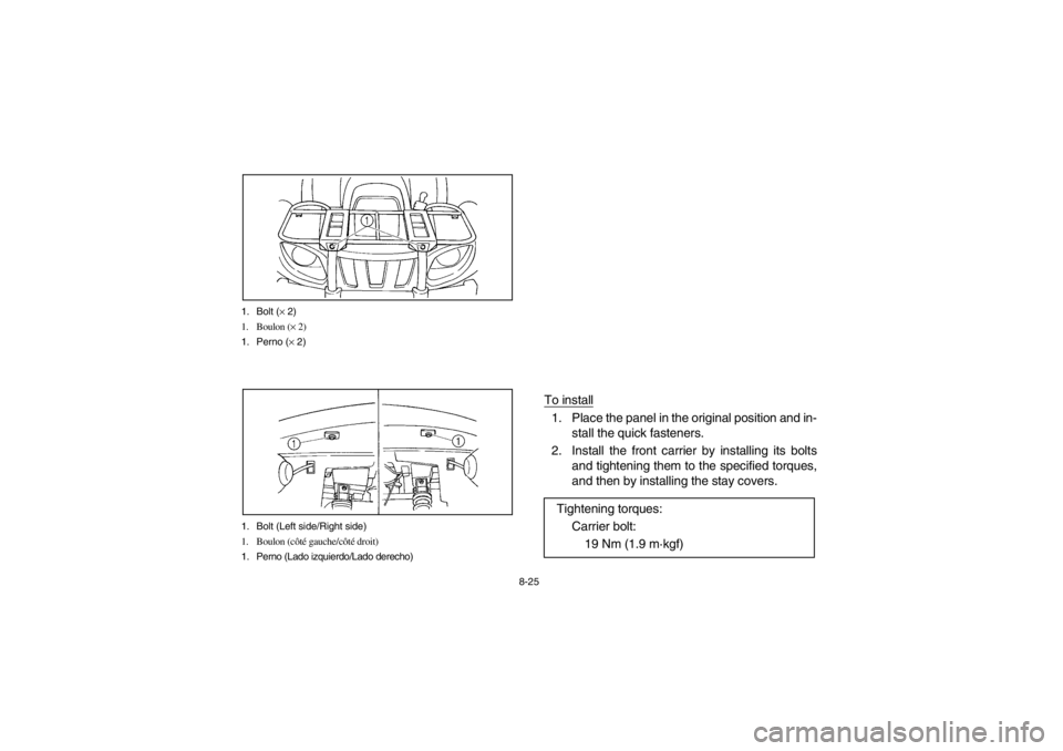
8-25 1. Bolt (× 2)
1. Boulon (× 2)
1. Perno (× 2)
1. Bolt (Left side/Right side)
1. Boulon (côté gauche/côté droit)
1. Perno (Lado izquierdo/Lado derecho)
To install1. Place the panel in the original position and in-
stall the quick fasteners.
2. Install the front carrier by installing its bolts
and tightening them to the specified torques,
and then by installing the stay covers.
Tightening torques:
Carrier bolt:
19 Nm (1.9 m·kgf)
U5KM60.book Page 25 Thursday, June 21, 2001 2:40 PM
Trending: reset, radiator, engine oil, weight, traction control, oil additives, cooling

