YAMAHA R6 RACE 2022 Owner's Manual
Manufacturer: YAMAHA, Model Year: 2022, Model line: R6 RACE, Model: YAMAHA R6 RACE 2022Pages: 112, PDF Size: 4.06 MB
Page 21 of 112
Instrument and control functions
4-2
4
EAU10474
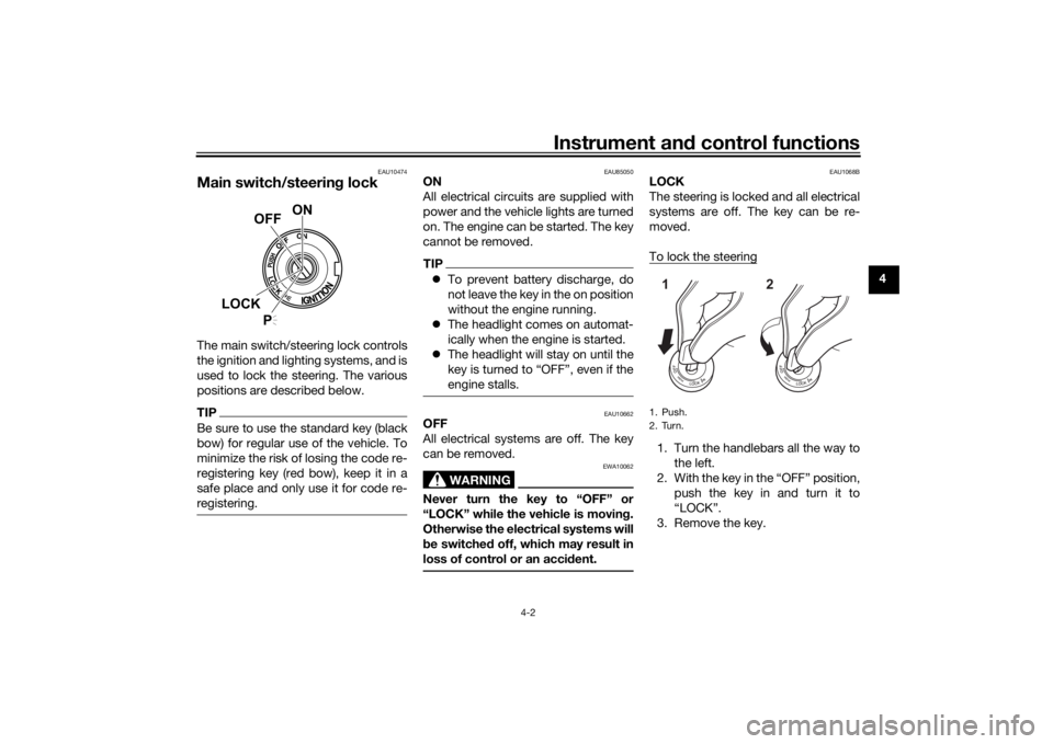
Main switch/steerin g lockThe main switch/steering lock controls
the ignition and lighting systems, and is
used to lock the steering. The various
positions are described below.TIPBe sure to use the standard key (black
bow) for regular use of the vehicle. To
minimize the risk of losing the code re-
registering key (red bow), keep it in a
safe place and only use it for code re-
registering.
EAU85050
ON
All electrical circuits are supplied with
power and the vehicle lights are turned
on. The engine can be started. The key
cannot be removed.TIP To prevent battery discharge, do
not leave the key in the on position
without the engine running.
The headlight comes on automat-
ically when the engine is started.
The headlight will stay on until the
key is turned to “OFF”, even if the
engine stalls.
EAU10662
OFF
All electrical systems are off. The key
can be removed.
WARNING
EWA10062
Never turn the key to “OFF” or
“LOCK” while the vehicle is movin g.
Otherwise the electrical systems will
b e switched off, which may result in
loss of control or an acci dent.
EAU1068B
LOCK
The steering is locked and all electrical
systems are off. The key can be re-
moved.
To lock the steering1. Turn the handlebars all the way to
the left.
2. With the key in the “OFF” position, push the key in and turn it to
“LOCK”.
3. Remove the key.
ON
OFF
LOCK
P
1. PushK
2. TurnK12
UBN6EBE0.book Page 2 Tuesday, October 19, 2021 8:35 AM
Page 22 of 112

Instrument and control functions
4-3
4
TIPIf the steering will not lock, try turning
the handlebars back to the right slight-
ly.To unlock the steeringFrom the “LOCK” position, push the
key in and turn it to “OFF”.
EAU59680
(Parkin g)
The hazard lights and turn signal lights
can be turned on, but all other electri-
cal systems are off. The key can be re-
moved.
The steering must be locked before the
key can be turned to “ ”.
NOTICE
ECA20760
Usin g the hazar d o r t ur n s i gnal li ghts
for an exten ded len gth of time may
cause the battery to d ischarge.
EAU66055
Han dle bar switchesLeft
1. Push.
2. Turn.12
1. Dimmer switch
Page 23 of 112

Instrument and control functions
4-4
4
Ri
ght
EAU79740
Pass switch “ ”
Press this switch to flash the headlight
and to mark the start of each lap when
using the lap timer.TIPWhen the dimmer switch is set
to Ž, the passing switch has no ef-
fect.
EAU79872
Dimmer switch “ / ”
Set this switch to “ ” for the high
beam and to “ ” for the low beam.
TIPWhen the switch is set to low beam,
only the left headlight comes on. When
the switch is set to high beam, both
headlights come on.
EAU66040
Turn si gnal switch “ / ”
To signal a right-hand turn, push this
switch to “ ”. To signal a left-hand
turn, push this switch to “ ”. When
released, the switch returns to the cen-
ter position. To cancel the turn signal
lights, push the switch in after it has re-
turned to the center position.
EAU66030
Horn switch “ ”
Press this switch to sound the horn.
EAU73961
Traction control system switch
“TCS”
See page 3-2 for an explanation of the
traction control system.
EAU66060
Stop/Run/Start switch “ / / ”
To crank the engine with the starter,
set this switch to “ ”, and then push
the switch down towards “ ”. See
page 6-1 for starting instructions prior
to starting the engine.
Set this switch to “ ” to stop the en-
gine in case of an emergency, such as
when the vehicle overturns or when the
throttle cable is stuck.
EAU66010
Hazar d switch “ ”
With the key in the “ON” or “ ” posi-
tion, use this switch to turn on the haz-
ard lights (simultaneous flashing of all
turn signal lights).
The hazard lights are used in case of an
emergency or to warn other drivers
when your vehicle is stopped where it
might be a traffic hazard.NOTICE
ECA10062
Do not use the hazar d lig hts for an
exten ded len gth of time with the en-
g ine not runnin g, otherwise the bat-
tery may d ischarge.
1. Stop/Run/Start switch “ / / ”
2. Drive mode switch “MODE”
3. Hazard switch “ ”
231
UBN6EBE0.book Page 4 Tuesday, October 19, 2021 8:35 AM
Page 24 of 112
Instrument and control functions
4-5
4
EAU73931
Drive mo de switch “MODE”
See page 3-1 for an explanation of the
drive mode.
EAU4939G
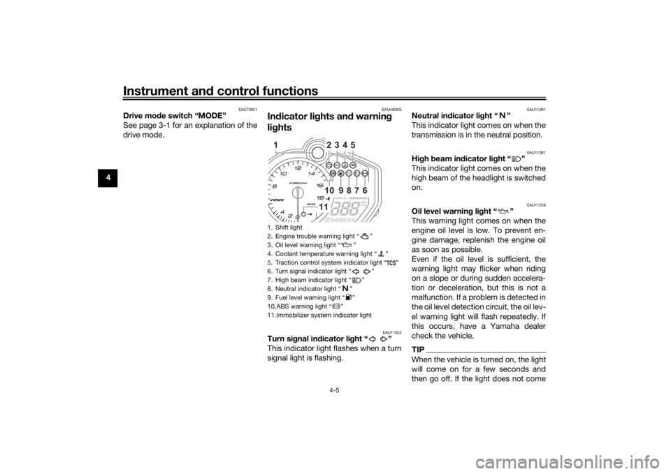
In dicator li ghts an d warnin g
li g hts
EAU11022
Turn si gnal in dicator li ght “ ”
This indicator light flashes when a turn
signal light is flashing.
EAU11061
Neutral in dicator li ght “ ”
This indicator light comes on when the
transmission is in the neutral position.
EAU11081
Hi gh beam in dicator li ght “ ”
This indicator light comes on when the
high beam of the headlight is switched
on.
EAU11259
Oil level warnin g li ght “ ”
This warning light comes on when the
engine oil level is low. To prevent en-
gine damage, replenish the engine oil
as soon as possible.
Even if the oil level is sufficient, the
warning light may flicker when riding
on a slope or during sudden accelera-
tion or deceleration, but this is not a
malfunction. If a problem is detected in
the oil level detection circuit, the oil lev-
el warning light will flash repeatedly. If
this occurs, have a Yamaha dealer
check the vehicle.TIPWhen the vehicle is turned on, the light
will come on for a few seconds and
then go off. If the light does not come
1. Shift light
2. Engine trouble warning light Ž
3. Oil level warning light Ž
4. Coolant temperature warning light Ž
5. Traction control system indicator light Ž
6. Turn signal indicator light Ž
7. High beam indicator light Ž
8. Neutral indicator light Ž
9. Fuel level warning light Ž
10.ABS warning light Ž
11.Immobilizer system indicator light
234510
9
8
7
6
11
1
ABS
UBN6EBE0.book Page 5 Tuesday, October 19, 2021 8:35 AM
Page 25 of 112
Instrument and control functions
4-6
4
on, or if the light remains on after con-
firming that the oil level is correct (see
page 7-15), have a Yamaha dealer
check the vehicle.
EAU11369
Fuel level warning
light “ ”
This warning light comes on when you
are low on fuel. When the fuel level
drops below approximately 3.4 L (0.90
US gal, 0.75 Imp.gal), the light will
come on to remind you to refuel as
soon as possible.
When the vehicle is turned on, the light
will perform a circuit check (come on
for a few seconds and then go off).
If the warning light does not come on
during the circuit check, or if the warn-
ing light remains on after refueling,
have a Yamaha dealer check the vehi-
cle.TIPIf a malfunction is detected, the fuel
level warning light will flash repeatedly.
Have a Yamaha dealer check the vehi-
cle.
EAU72931
Coolant temperature warnin g
li g ht “ ”
This warning light comes on if the en-
gine overheats. If this occurs, reduce
the load on the engine immediately. If
message “HI” flashes in the coolant
temperature display, stop the vehicle,
then stop the engine and let the engine
cool.
The electrical circuit of the warning
light can be checked by turning the ve-
hicle on. The warning light should
come on for a few seconds, and then
go off.
If the warning light does not come on
initially when the vehicle is turned on,
or if the warning light remains on, have
a Yamaha dealer check the electrical
circuit.NOTICE
ECA10022
Do not continue to operate the en-
g ine if it is overheatin g.
TIP For radiator-fan-equipped vehi-
cles, the radiator fan(s) automati-
cally switch on or off according to
the coolant temperature in the ra-
diator.
If the engine overheats, see page
7-42 for further instructions.
EAU73172
Engine trou ble warnin g li ght “ ”
This warning light comes on if a prob-
lem is detected in the engine or other
vehicle control system. If this occurs,
have a Yamaha dealer check the on-
board diagnostic system.TIPWhen the vehicle is turned on, the light
will come on for a few seconds and
then go off. If the light does not come
on, or if the light remains on, have a
Yamaha dealer check the vehicle.
UBN6EBE0.book Page 6 Tuesday, October 19, 2021 8:35 AM
Page 26 of 112
Instrument and control functions
4-7
4
EAU69893
ABS warnin g li ght “ ”
This warning light comes on when the
vehicle is first turned on, and goes off
after starting riding. If the warning light
comes on while riding, the anti-lock
brake system may not work correctly.
WARNING
EWA16041
If the ABS warnin g li ght does not go
off after travelin g at a speed of 10
km/h (6 mi/h) or hi gher, or if the
warnin g li ght comes on or flashes
while ri din g, the b rake system re-
verts to conventional brakin g. If ei-
ther of the ab ove occurs, or if the
warnin g li ght does not come on at
all, use extra caution to avoi d possi-
b le wheel lock during emer gency
b rakin g. Have a Yamaha d ealer
check the brake system an d electri-
cal circuits as soon as possi ble.
EAU86020
Traction control system in dicator
li g ht “ ”
This indicator light will flash when trac-
tion control has engaged.
If the traction control system is turned
off, this indicator light will come on.
TIPWhen the vehicle is turned on, the light
should come on for a few seconds and
then go off. If the light does not come
on, or if the light remains on, have a
Yamaha dealer check the vehicle.
EAU80372
Shift li ght
This light can be set to come on and go
off at select engine speeds. (See page
4-15.)TIPWhen the vehicle is turned on, the light
will come on for a few seconds and
then go off. If the light does not come
on, have a Yamaha dealer check the
vehicle.
EAU80300
Immo bilizer system in dicator li ght
When the key is turned to “OFF” and
30 seconds have passed, the indicator
light will flash steadily to indicate the
immobilizer system is enabled. After 24
hours have passed, the indicator light
will stop flashing, however the immobi-
lizer system is still enabled. The electrical circuit of the indicator
light can be checked by turning the key
to “ON”. The indicator light should
come on for a few seconds, and then
go off.
If the indicator light does not come on
initially when the key is turned to “ON”,
if the indicator light remains on, or if the
indicator light flashes in a pattern (if a
problem is detected in the immobilizer
system, the immobilizer system indica-
tor light will flash in a pattern), have a
Yamaha dealer check the vehicle.
TIPIf the immobilizer system indicator light
flashes in the pattern, slowly 5 times
then quickly 2 times, this could be
caused by transponder interference. If
this occurs, try the following.1. Make sure there are no other im- mobilizer keys close to the main
switch. Other immobilizer system
keys may cause signal interfer-
ence and prevent the engine from
starting.
2. Use the code re-registering key to start the engine.
ABS
UBN6EBE0.book Page 7 Tuesday, October 19, 2021 8:35 AM
Page 27 of 112
Instrument and control functions
4-8
4
3. If the engine starts, turn it off, and
try starting the engine with the
standard keys.
4. If one or both of the standard keys do not start the engine, take the
vehicle and all 3 keys to a Yamaha
dealer to have the standard keys
re-registered.
EAU3904H
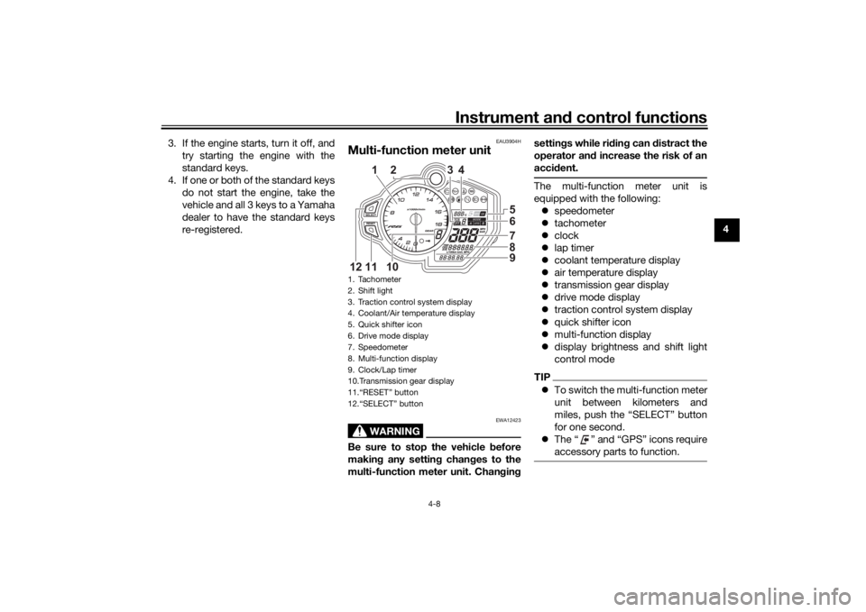
Multi-function meter unit
WARNING
EWA12423
Be sure to stop the vehicle before
makin g any settin g chan ges to the
multi-function meter unit. Chan gin g settin
gs while ri din g can d istract the
operator an d increase the risk of an
acci dent.
The multi-function meter unit is
equipped with the following:
speedometer
tachometer
clock
lap timer
coolant temperature display
air temperature display
transmission gear display
drive mode display
traction control system display
quick shifter icon
multi-function display
display brightness and shift light
control modeTIPTo switch the multi-function meter
unit between kilometers and
miles, push the “SELECT” button
for one second.
The “ ” and “GPS” icons require
accessory parts to function.
1. Tachometer
2. Shift light
3. Traction control system display
4. Coolant/Air temperature display
5. Quick shifter icon
6. Drive mode display
7. Speedometer
8. Multi-function display
9. Clock/Lap timer
10.Transmission gear display
11.“RESET” button
12.“SELECT” button
65789
2
3
4
10
11
12
1
UBN6EBE0.book Page 8 Tuesday, October 19, 2021 8:35 AM
Page 28 of 112
Instrument and control functions
4-9
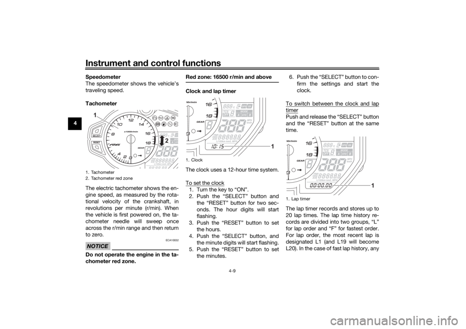
4 Speed
ometer
The speedometer shows the vehicle’s
traveling speed.
Tachometer
The electric tachometer shows the en-
gine speed, as measured by the rota-
tional velocity of the crankshaft, in
revolutions per minute (r/min). When
the vehicle is first powered on, the ta-
chometer needle will sweep once
across the r/min range and then return
to zero.
NOTICE
ECA10032
Do not operate the en gine in the ta-
chometer red zone. Re
d zone: 16500 r/min an d a bove
Clock an d lap timer
The clock uses a 12-hour time system.
To set the clock1. Turn the key to “ON”.
2. Push the “SELECT” button and the “RESET” button for two sec-
onds. The hour digits will start
flashing.
3. Push the “RESET” button to set the hours.
4. Push the “SELECT” button, and the minute digits will start flashing.
5. Push the “RESET” button to set the minutes. 6. Push the “SELECT” button to con-
firm the settings and start the
clock.
To switch between the clock and lap
timerPush and release the “SELECT” button
and the “RESET” button at the same
time.
The lap timer records and stores up to
20 lap times. The lap time history re-
cords are divided into two groups, “L”
for lap order and “F” for fastest order.
For lap order, the most recent lap is
designated L1 (and L19 will become
L20). In the case of fast lap history, any
1. Tachometer
2. Tachometer red zone
2
1
1. Clock
1
1. Lap timer
1
UBN6EBE0.book Page 9 Tuesday, October 19, 2021 8:35 AM
Page 29 of 112
Instrument and control functions
4-10
4
new fast lap within the top 20 will be in-
serted and the previous F20 will be
pushed out of the history.
To use the lap timer
1. Push the “RESET” button for one
second to set the lap timer to the
counting-ready state (the colon “:”
and period “.” will flash).
2. Push the pass switch “ ” to start the lap timer.
3. Push the pass switch “ ” to mark the start of each new lap.
4. Push the “SELECT” button to stop the lap timer.
5. Push the “SELECT” button again to reset the lap timer (or push the
“RESET” button for one second to
reset the lap timer and set it to the
counting-ready state).
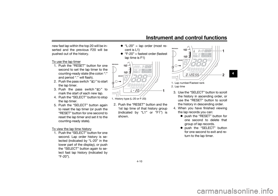
To view the lap time history1. Push the “SELECT” button for one second. Lap order history is se-
lected (indicated by “L-20” in the
lower part of the display), or push
the “SELECT” button again to se-
lect fast lap history (indicated by
“F-20”).
“L-20” = lap order (most re-
cent is L1)
“F-20” = fastest order (fastest
lap time is F1)
2. Push the “RESET” button and the 1st lap time of that history group
(indicated by “L1” or “F1”) is
shown. 3. Use the “SELECT” button to scroll
the history in ascending order, or
use the “RESET” button to scroll
the history in descending order.
4. When you have finished viewing the lap records you can: push the “RESET” button for
one second to delete that
group of lap records.
push the “SELECT” button
for one second to exit and re-
turn to the lap timer.
1. History type (L-20 or F-20)
1
1. Lap number/Fastest rank
2. Lap time
12
UBN6EBE0.book Page 10 Tuesday, October 19, 2021 8:35 AM
Page 30 of 112
Instrument and control functions
4-11
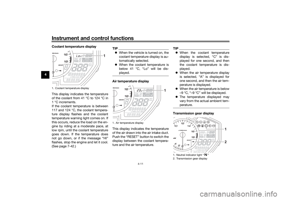
4 Coolant temperature
display
This display indicates the temperature
of the coolant from 41 °C to 124 °C in
1 °C increments.
If the coolant temperature is between
117 and 124 °C, the coolant tempera-
ture display flashes and the coolant
temperature warning light comes on. If
this occurs, reduce the load on the en-
gine by riding at a moderate pace, at
low rpm, until the coolant temperature
goes down. If the temperature does
not go down, or if the message “HI”
flashes, stop the engine and let it cool.
(See page 7-42.)
TIP When the vehicle is turned on, the
coolant temperature display is au-
tomatically selected.
When the coolant temperature is
below 41 °C, “Lo” will be dis-
played.Air temperature d isplay
This display indicates the temperature
of the air drawn into the air intake duct.
Push the “RESET” button to switch the
display between the coolant tempera-
ture and the air temperature.
TIP When the coolant temperature
display is selected, “C” is dis-
played for one second, and then
the coolant temperature is dis-
played.
When the air temperature display
is selected, “A” is displayed for
one second, and then the air tem-
perature is displayed.
When the air temperature is below
–9 °C, “–9 °C” will be displayed.
The temperature displayed may
vary from the actual ambient tem-
perature.Transmission gear display
1. Coolant temperature display
1
1. Air temperature display
1
1. Neutral indicator light