YAMAHA TMAX 2002 Owners Manual
Manufacturer: YAMAHA, Model Year: 2002, Model line: TMAX, Model: YAMAHA TMAX 2002Pages: 102, PDF Size: 1.67 MB
Page 91 of 102
8-1
EAU01038
SPECIFICATIONS
8
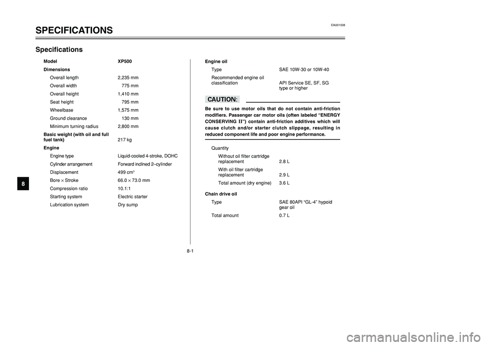
SpecificationsSpecifications
Model XP500
Dimensions
Overall length 2,235 mm
Overall width 775 mm
Overall height 1,410 mm
Seat height 795 mm
Wheelbase 1,575 mm
Ground clearance 130 mm
Minimum turning radius 2,800 mm
Basic weight (with oil and full
fuel tank)217 kg
Engine
Engine type Liquid-cooled 4-stroke, DOHC
Cylinder arrangement Forward inclined 2–cylinder
Displacement 499 cm
3
Bore ×Stroke 66.0 ×73.0 mm
Compression ratio 10.1:1
Starting system Electric starter
Lubrication system Dry sumpEngine oil
Type SAE 10W-30 or 10W-40
Recommended engine oil
classification API Service SE, SF, SG
type or higher
cCBe sure to use motor oils that do not contain anti-friction
modifiers. Passenger car motor oils (often labeled “ENERGY
CONSERVING
II”) contain anti-friction additives which will
cause clutch and/or starter clutch slippage, resulting in
reduced component life and poor engine performance.
Quantity
Without oil filter cartridge
replacement 2.8 L
With oil filter cartridge
replacement 2.9 L
Total amount (dry engine) 3.6 L
Chain drive oil
Type SAE 80API “GL-4” hypoid
gear oil
Total amount 0.7 L
5GJ-9-E1 9/4/01 1:27 PM Page 90
Page 92 of 102
8-2
SPECIFICATIONS
8
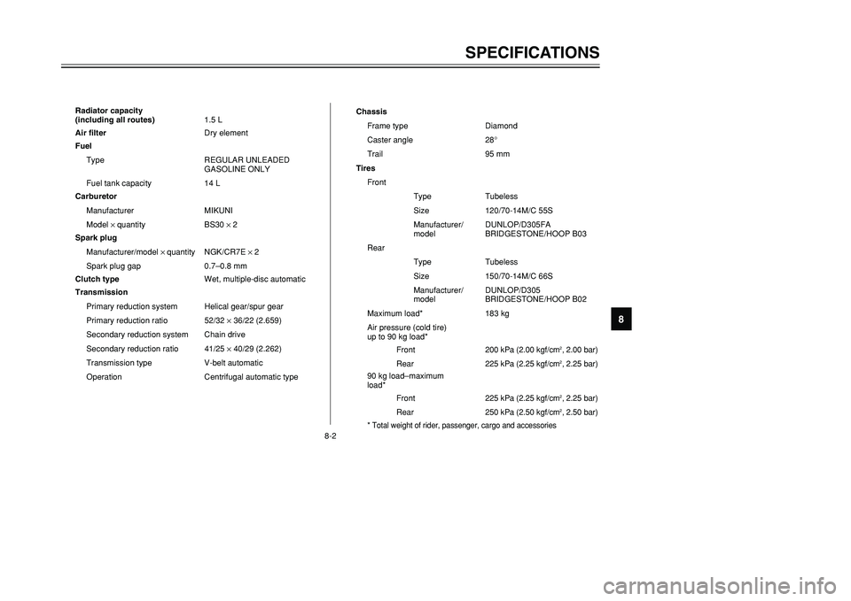
Radiator capacity
(including all routes)1.5 L
Air filterDry element
Fuel
Type REGULAR UNLEADED
GASOLINE ONLY
Fuel tank capacity 14 L
Carburetor
Manufacturer MIKUNI
Model × quantity BS30 × 2
Spark plug
Manufacturer/model × quantity NGK/CR7E × 2
Spark plug gap 0.7–0.8 mm
Clutch typeWet, multiple-disc automatic
Transmission
Primary reduction system Helical gear/spur gear
Primary reduction ratio 52/32 ×36/22 (2.659)
Secondary reduction system Chain drive
Secondary reduction ratio 41/25 ×40/29 (2.262)
Transmission type V-belt automatic
Operation Centrifugal automatic typeChassis
Frame type Diamond
Caster angle 28°
Trail 95 mm
Tires
Front
Type Tubeless
Size 120/70-14M/C 55S
Manufacturer/ DUNLOP/D305FA
model BRIDGESTONE/HOOP B03
Rear
Type Tubeless
Size 150/70-14M/C 66S
Manufacturer/ DUNLOP/D305
model BRIDGESTONE/HOOP B02
Maximum load* 183 kg
Air pressure (cold tire)
up to 90 kg load*
Front200 kPa (2.00 kgf/cm
2, 2.00 bar)
Rear225 kPa (2.25 kgf/cm2, 2.25 bar)
90 kg load–maximum
load*
Front225 kPa (2.25 kgf/cm2, 2.25 bar)
Rear250 kPa (2.50 kgf/cm2, 2.50 bar)
* Total weight of rider, passenger, cargo and accessories
5GJ-9-E1 9/4/01 1:27 PM Page 91
Page 93 of 102
8-3
SPECIFICATIONS
8
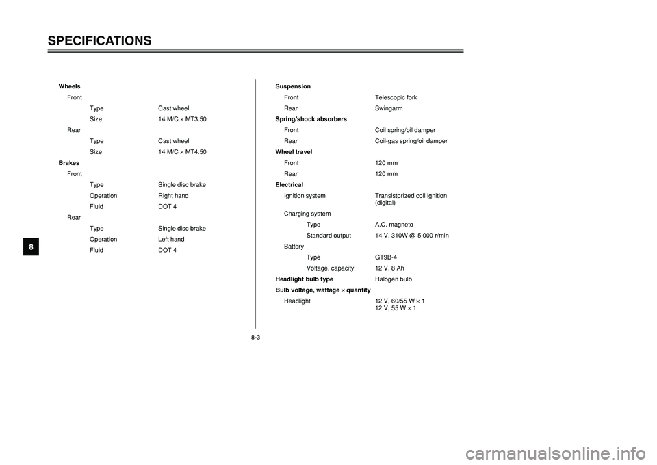
Wheels
Front
Type Cast wheel
Size 14 M/C ×MT3.50
Rear
Type Cast wheel
Size 14 M/C ×MT4.50
Brakes
Front
Type Single disc brake
Operation Right hand
Fluid DOT 4
Rear
Type Single disc brake
Operation Left hand
Fluid DOT 4Suspension
Front Telescopic fork
Rear Swingarm
Spring/shock absorbers
Front Coil spring/oil damper
Rear Coil-gas spring/oil damper
Wheel travel
Front 120 mm
Rear 120 mm
Electrical
Ignition system Transistorized coil ignition
(digital)
Charging system
Type A.C. magneto
Standard output 14 V, 310W @ 5,000 r/min
Battery
Type GT9B-4
Voltage, capacity 12 V, 8 Ah
Headlight bulb typeHalogen bulb
Bulb voltage, wattage ×quantity
Headlight 12 V, 60/55 W ×1
12 V, 55 W ×1
5GJ-9-E1 9/4/01 1:27 PM Page 92
Page 94 of 102

8-4
SPECIFICATIONS
8
Tail/brake light 12 V, 5/21 W ×2
Front turn signal light 12 V, 5/21 W ×2
Rear turn signal light 12 V, 21 W ×2
Auxiliary light 12 V, 5 W ×2
License plate light 12 V, 5 W ×1
Meter lighting 12 V, 1.7 W ×3
High beam indicator light 12 V, 1.7 W ×1
Oil change indicator light 12 V, 1.7 W ×1
Turn indicator light 12 V, 3.4 W ×2
V-belt replacement
indicator light 12 V, 1.7 W ×1
Fuses
Main fuse 30 A
Signaling system fuse 15 A
Headlight fuse 15 A
Ignition fuse 10 A
Radiator fan fuse 15 A
Hazard fuse 10 A
Clock fuse 10 A
5GJ-9-E1 9/4/01 1:27 PM Page 93
Page 95 of 102

8-5
SPECIFICATIONS
8
EAU03941
Conversion tableConversion table
Conversion tableAll specification data in this manual are listed in SI and
METRIC UNITS.
Use this table to convert METRIC unit values to IMPERIAL
unit values.
Example:METRIC VALUE CONVERSION
FACTORIMPERIAL VALUE
2 mm× 0.03937 = 0.08 in
Conversion table
METRIC SYSTEM TO IMPERIAL SYSTEM
Metric unit Conversion factor Imperial unit
Torquem·kgf
m·kgf
cm·kgf
cm·kgf
× 7.233× 86.794× 0.0723× 0.8679ft·lb
in·lb
ft·lb
in·lb
Weightkg
g× 2.205× 0.03527lb
oz
Speed km/h× 0.6214 mi/h
Distancekm
m
m
cm
mm× 0.6214× 3.281× 1.094× 0.3937× 0.03937mi
ft
yd
in
in
Volume,
Capacitycc (cm
3)
cc (cm3)
L (liter)
L (liter)
× 0.03527× 0.06102× 0.8799× 0.2199oz (IMP liq.)
cu·in
qt (IMP liq.)
gal (IMP liq.)
Miscellaneouskgf/mm
kgf/cm
2
°C
× 55.997× 14.2234× 1.8 + 32 lb/in
psi (lb/in
2)
°F
5GJ-9-E1 9/4/01 1:27 PM Page 94
Page 96 of 102

CONSUMER INFORMATION
Identification numbers ...................................................................... 9-1
Key identification number ................................................................. 9-1
Vehicle identification number ............................................................ 9-1
Model label ....................................................................................... 9-2
9
5GJ-9-E1 9/4/01 1:27 PM Page 95
Page 97 of 102

9-1
EAU01039
CONSUMER INFORMATION
9
EAU02944
Identification numbersIdentification numbersRecord the key identification number,
vehicle identification number and
model label information in the spaces
provided below for assistance when
ordering spare parts from a Yamaha
dealer or for reference in case the
vehicle is stolen.
1. KEY IDENTIFICATION
NUMBER:
2. VEHICLE IDENTIFICATION
NUMBER:
3. MODEL LABEL INFORMATION:
EAU01044
Vehicle identification numberThe vehicle identification number is
stamped into the frame.NOTE:
The vehicle identification number is
used to identify your scooter and may
be used to register your scooter with
the licensing authority in your area.
1
1. Vehicle identification number
EAU01041
Key identification numberKey identification numberThe key identification number is
stamped into the key tag.
Record this number in the space pro-
vided and use it for reference when
ordering a new key.
1
1. Key identification number
1
6
5GJ-9-E1 9/4/01 1:27 PM Page 96
Page 98 of 102

9-2
CONSUMER INFORMATION
9
EAU03757
Model labelModel labelThe model label is affixed to the loca-
tion shown. Record the information
on this label in the space provided.
This information will be needed when
ordering spare parts from a Yamaha
dealer.
1
1. Model label
5GJ-9-E1 9/4/01 1:27 PM Page 97
Page 99 of 102
INDEX
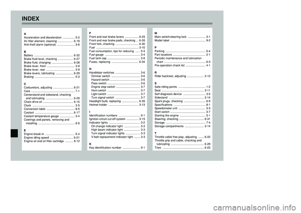
F
Front and rear brake levers ................. 6-25
Front and rear brake pads, checking ... 6-26
Front fork, checking ............................. 6-30
Fuel ..................................................... 3-10
Fuel consumption, tips for reducing ...... 5-3
Fuel gauge ............................................ 3-4
Fuel tank cap ......................................... 3-9
Fuses, replacing .................................. 6-34
H
Handlebar switches ............................... 3-6
Dimmer switch .................................... 3-6
Hazard switch ...................................... 3-6
Pass switch ......................................... 3-6
Engine stop switch .............................. 3-7
Horn switch ......................................... 3-7
Light switch ......................................... 3-7
Turn signal switch ............................... 3-7
Headlight bulb, replacing ..................... 6-35
Helmet holder ...................................... 3-13
I
Identification numbers ........................... 9-1
Ignition circuit cut-off system ............... 3-15
Indicator lights ....................................... 3-2
Oil change indicator light .................... 3-2
High beam indicator light .................... 3-3
Turn signal indicator lights .................. 3-3
V-belt replacement indicator light ....... 3-3
K
Key identification number ...................... 9-1
M
Main switch/steering lock ...................... 3-1
Model label ............................................ 9-2
P
Parking .................................................. 5-4
Part locations ......................................... 2-1
Periodic maintenance and lubrication
chart .................................................... 6-3
Pre-operation check list ......................... 4-1
R
Rider backrest, adjusting ..................... 3-12
S
Safe-riding points .................................. 1-2
Seat ..................................................... 3-11
Self-diagnosis device ............................ 3-5
Sidestand ............................................ 3-14
Spark plugs, checking ........................... 6-9
Specifications ........................................ 8-1
Speedometer unit .................................. 3-3
Start switch ............................................ 3-7
Starting the engine ................................ 5-1
Steering, checking ............................... 6-31
Storage .................................................. 7-4
Storage compartments ........................ 3-14
T
Throttle cable free play, adjusting ....... 6-22
Throttle grip and cable, checking and
lubricating ......................................... 6-29
Tires .................................................... 6-23
A
Acceleration and deceleration ............... 5-2
Air filter element, cleaning ................... 6-19
Anti-theft alarm (optional) ...................... 3-6
B
Battery ................................................. 6-32
Brake fluid level, checking ................... 6-27
Brake fluid, changing ........................... 6-28
Brake lever, front ................................... 3-9
Brake lever, rear .................................... 3-9
Brake levers, lubricating ...................... 6-29
Braking .................................................. 5-3
C
Carburetors, adjusting ......................... 6-21
Care ....................................................... 7-1
Centerstand and sidestand, checking
and lubricating .................................. 6-29
Chain drive oil ...................................... 6-15
Clock ..................................................... 3-5
Conversion table ................................... 8-5
Coolant ................................................ 6-17
Coolant temperature gauge ................... 3-4
Cowlings and panels, removing and
installing .............................................. 6-6
E
Engine break-in ..................................... 5-4
Engine idling speed ............................. 6-21
Engine oil and oil filter cartridge .......... 6-12
5GJ-9-E1 9/4/01 1:27 PM Page 98
Page 100 of 102
Tool kit ................................................... 6-1
Troubleshooting ................................... 6-36
Troubleshooting charts ........................ 6-37
V
Valve clearance, adjusting .................. 6-22
W
Wheel bearings, checking ................... 6-31
Wheels ................................................ 6-25
INDEX
5GJ-9-E1 9/4/01 1:27 PM Page 99