fuse YAMAHA TMAX 2002 Owners Manual
[x] Cancel search | Manufacturer: YAMAHA, Model Year: 2002, Model line: TMAX, Model: YAMAHA TMAX 2002Pages: 102, PDF Size: 1.67 MB
Page 14 of 102

2-2
DESCRIPTION
2
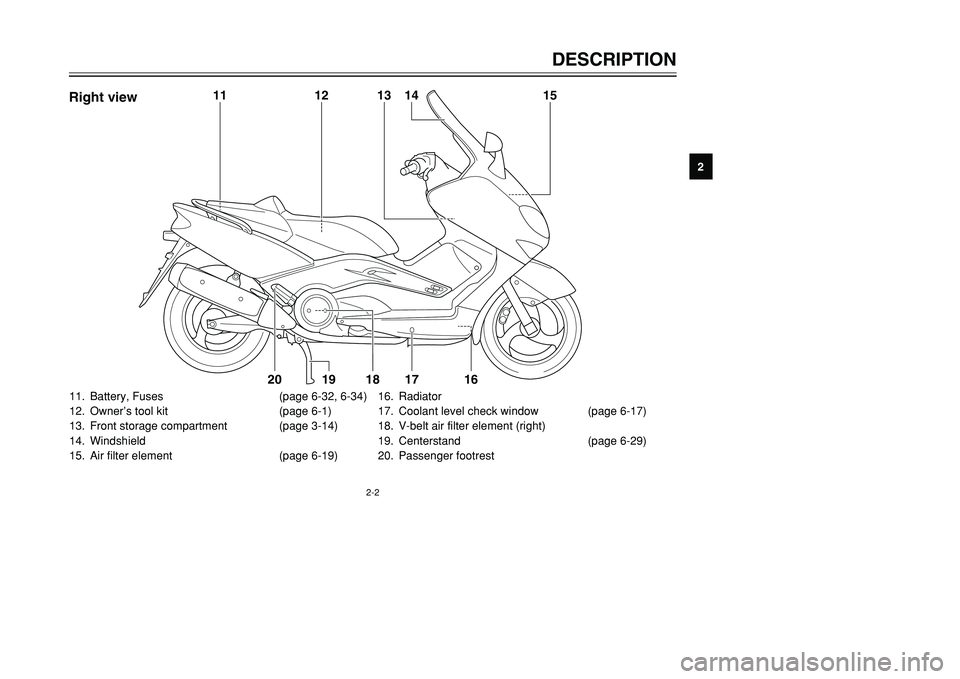
11. Battery, Fuses (page 6-32, 6-34)
12. Owner’s tool kit (page 6-1)
13. Front storage compartment (page 3-14)
14. Windshield
15. Air filter element (page 6-19)16. Radiator
17. Coolant level check window (page 6-17)
18. V-belt air filter element (right)
19. Centerstand (page 6-29)
20. Passenger footrest
11
12
13
14
15
18
17
16
19
20
Right view
5GJ-9-E1 9/4/01 1:27 PM Page 13
Page 44 of 102

PERIODIC MAINTENANCE AND MINOR REPAIR
Owner’s tool kit ..................................................... 6-1
Periodic maintenance and lubrication chart .......... 6-3
Removing and installing cowlings and panels ...... 6-6
Checking the spark plugs ..................................... 6-9
Engine oil and oil filter cartridge .......................... 6-12
Chain drive oil ..................................................... 6-15
Coolant ............................................................... 6-17
Cleaning the air filter element ............................. 6-19
Adjusting the carburetors .................................... 6-21
Adjusting the engine idling speed ....................... 6-21
Adjusting the throttle cable free play ................... 6-22
Adjusting the valve clearance ............................. 6-22
Tires .................................................................... 6-23
Cast wheels ........................................................ 6-25
Front and rear brake levers ................................ 6-25
Checking the front and rear brake pads ............. 6-26
Checking the brake fluid level ............................. 6-27
Changing the brake fluid ..................................... 6-28
Checking and lubricating the throttle grip
and cable .......................................................... 6-29
Lubricating the front and rear brake levers ......... 6-29
Checking and lubricating the centerstand and
sidestand .......................................................... 6-29
Checking the front fork ........................................ 6-30Checking the steering ......................................... 6-31
Checking the wheel bearings .............................. 6-31
Battery ................................................................ 6-32
Replacing the fuses ............................................ 6-34
Replacing a headlight bulb ................................. 6-35
Troubleshooting .................................................. 6-36
Troubleshooting charts ....................................... 6-37
6
5GJ-9-E1 9/4/01 1:27 PM Page 43
Page 78 of 102

6-34
PERIODIC MAINTENANCE AND MINOR REPAIR
6
EAU04404
Replacing the fusesFuses, replacingThe main fuse box is located beside
the battery and can be accessed as
follows:
1. Open the seat. (See page 3-11
for seat opening and closing pro-
cedures.)
2. Remove the battery cover. (See
page 6-32 for battery cover
removal procedures.)
1
1. Battery
If a fuse is blown, replace it as fol-
lows.
1. Turn the key to “OFF” and turn
off the electrical circuit in ques-
tion.
2. Remove the blown fuse, and
then install a new fuse of the
specified amperage.
7
123456
1. Signaling system fuse
2. Headlight fuse
3. Ignition fuse
4. Radiator fan fuse
5. Hazard fuse
6. Clock fuse
7. Spare fuse (×2)
3. Disconnect the negative battery
lead, and then lift the battery as
shown.
The fuse box, which contains the
fuses for the individual circuits, is
located under the battery cover and
can be accessed as follows.
1. Open the seat. (See page 3-11
for seat opening and closing pro-
cedures.)
2. Remove the battery cover by
removing the screws.
12
3
1. Negative battery lead
2. Main fuse box
3. Fuse box
5GJ-9-E1 9/4/01 1:27 PM Page 77
Page 79 of 102

6-35
PERIODIC MAINTENANCE AND MINOR REPAIR
6
EC000103
cCDo not use a fuse of a higher
amperage rating than recommend-
ed to avoid causing extensive
damage to the electrical system
and possibly a fire.3. Turn the key to “ON” and turn on
the electrical circuit in question to
check if the device operates.
4. If the fuse immediately blows
again, have a Yamaha dealer
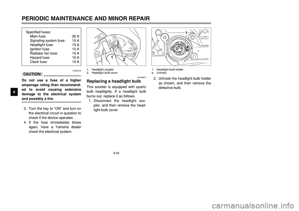
check the electrical system.2. Unhook the headlight bulb holder
as shown, and then remove the
defective bulb.
a
1
1. Headlight bulb holder
a. Unhook.
EAU03874
Replacing a headlight bulbHeadlight bulb, replacingThis scooter is equipped with quartz
bulb headlights. If a headlight bulb
burns out, replace it as follows.
1. Disconnect the headlight cou-
pler, and then remove the head-
light bulb cover.
1
2
1. Headlight coupler
2. Headlight bulb cover
Specified fuses:
Main fuse: 30 A
Signaling system fuse: 15 A
Headlight fuse: 15 A
Ignition fuse: 10 A
Radiator fan fuse: 15 A
Hazard fuse: 10 A
Clock fuse: 10 A
5GJ-9-E1 9/4/01 1:27 PM Page 78
Page 94 of 102

8-4
SPECIFICATIONS
8
Tail/brake light 12 V, 5/21 W ×2
Front turn signal light 12 V, 5/21 W ×2
Rear turn signal light 12 V, 21 W ×2
Auxiliary light 12 V, 5 W ×2
License plate light 12 V, 5 W ×1
Meter lighting 12 V, 1.7 W ×3
High beam indicator light 12 V, 1.7 W ×1
Oil change indicator light 12 V, 1.7 W ×1
Turn indicator light 12 V, 3.4 W ×2
V-belt replacement
indicator light 12 V, 1.7 W ×1
Fuses
Main fuse 30 A
Signaling system fuse 15 A
Headlight fuse 15 A
Ignition fuse 10 A
Radiator fan fuse 15 A
Hazard fuse 10 A
Clock fuse 10 A
5GJ-9-E1 9/4/01 1:27 PM Page 93
Page 99 of 102

INDEX
F
Front and rear brake levers ................. 6-25
Front and rear brake pads, checking ... 6-26
Front fork, checking ............................. 6-30
Fuel ..................................................... 3-10
Fuel consumption, tips for reducing ...... 5-3
Fuel gauge ............................................ 3-4
Fuel tank cap ......................................... 3-9
Fuses, replacing .................................. 6-34
H
Handlebar switches ............................... 3-6
Dimmer switch .................................... 3-6
Hazard switch ...................................... 3-6
Pass switch ......................................... 3-6
Engine stop switch .............................. 3-7
Horn switch ......................................... 3-7
Light switch ......................................... 3-7
Turn signal switch ............................... 3-7
Headlight bulb, replacing ..................... 6-35
Helmet holder ...................................... 3-13
I
Identification numbers ........................... 9-1
Ignition circuit cut-off system ............... 3-15
Indicator lights ....................................... 3-2
Oil change indicator light .................... 3-2
High beam indicator light .................... 3-3
Turn signal indicator lights .................. 3-3
V-belt replacement indicator light ....... 3-3
K
Key identification number ...................... 9-1
M
Main switch/steering lock ...................... 3-1
Model label ............................................ 9-2
P
Parking .................................................. 5-4
Part locations ......................................... 2-1
Periodic maintenance and lubrication
chart .................................................... 6-3
Pre-operation check list ......................... 4-1
R
Rider backrest, adjusting ..................... 3-12
S
Safe-riding points .................................. 1-2
Seat ..................................................... 3-11
Self-diagnosis device ............................ 3-5
Sidestand ............................................ 3-14
Spark plugs, checking ........................... 6-9
Specifications ........................................ 8-1
Speedometer unit .................................. 3-3
Start switch ............................................ 3-7
Starting the engine ................................ 5-1
Steering, checking ............................... 6-31
Storage .................................................. 7-4
Storage compartments ........................ 3-14
T
Throttle cable free play, adjusting ....... 6-22
Throttle grip and cable, checking and
lubricating ......................................... 6-29
Tires .................................................... 6-23
A
Acceleration and deceleration ............... 5-2
Air filter element, cleaning ................... 6-19
Anti-theft alarm (optional) ...................... 3-6
B
Battery ................................................. 6-32
Brake fluid level, checking ................... 6-27
Brake fluid, changing ........................... 6-28
Brake lever, front ................................... 3-9
Brake lever, rear .................................... 3-9
Brake levers, lubricating ...................... 6-29
Braking .................................................. 5-3
C
Carburetors, adjusting ......................... 6-21
Care ....................................................... 7-1
Centerstand and sidestand, checking
and lubricating .................................. 6-29
Chain drive oil ...................................... 6-15
Clock ..................................................... 3-5
Conversion table ................................... 8-5
Coolant ................................................ 6-17
Coolant temperature gauge ................... 3-4
Cowlings and panels, removing and
installing .............................................. 6-6
E
Engine break-in ..................................... 5-4
Engine idling speed ............................. 6-21
Engine oil and oil filter cartridge .......... 6-12
5GJ-9-E1 9/4/01 1:27 PM Page 98