display YAMAHA TMAX 2017 User Guide
[x] Cancel search | Manufacturer: YAMAHA, Model Year: 2017, Model line: TMAX, Model: YAMAHA TMAX 2017Pages: 124, PDF Size: 14.56 MB
Page 43 of 124
Instrument and control functions
5-10
1
2
3
4
5
6
7
8
9
10
11
12
13
14
TIP
–9 C will be displayed even if the
detected temperature is lower.
50 C will be displayed even if the
detected temperature is higher.
The accuracy of the temperature
reading may be affected when rid-
ing under 20 km/h (12 mi/h) or
when stopped at traffic signals and
railroad crossings.
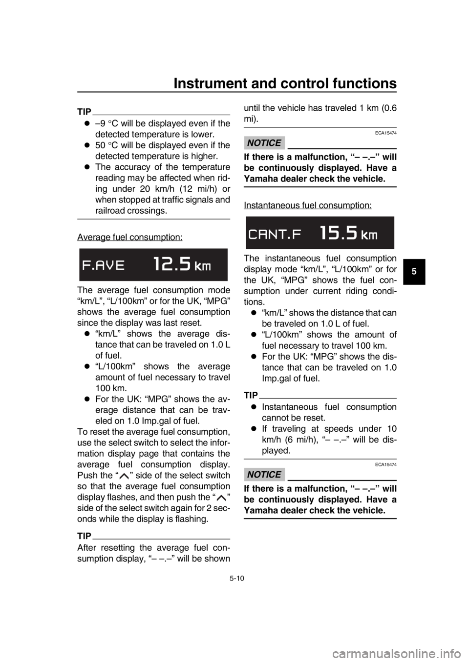
Average fuel consumption:
The average fuel consumption mode
“km/L”, “L/100km” or for the UK, “MPG”
shows the average fuel consumption
since the display was last reset.
“km/L” shows the average dis-
tance that can be traveled on 1.0 L
of fuel.
“L/100km” shows the average
amount of fuel necessary to travel
100 km.
For the UK: “MPG” shows the av-
erage distance that can be trav-
eled on 1.0 Imp.gal of fuel.
To reset the average fuel consumption,
use the select switch to select the infor-
mation display page that contains the
average fuel consumption display.
Push the “ ” side of the select switch
so that the average fuel consumption
display flashes, and then push the “ ”
side of the select switch again for 2 sec-
onds while the display is flashing.
TIP
After resetting the average fuel con-
sumption display, “– –.–” will be shown until the vehicle has traveled 1 km (0.6
mi).
NOTICE
ECA15474
If there is a malfunction, “– –.–” will
be continuously displayed. Have a
Yamaha dealer check the vehicle.
Instantaneous fuel consumption:
The instantaneous fuel consumption
display mode “km/L”, “L/100km” or for
the UK, “MPG” shows the fuel con-
sumption under current riding condi-
tions.
“km/L” shows the distance that can
be traveled on 1.0 L of fuel.
“L/100km” shows the amount of
fuel necessary to travel 100 km.
For the UK: “MPG” shows the dis-
tance that can be traveled on 1.0
Imp.gal of fuel.
TIP
Instantaneous fuel consumption
cannot be reset.
If traveling at speeds under 10
km/h (6 mi/h), “– –.–” will be dis-
played.
NOTICE
ECA15474
If there is a malfunction, “– –.–” will
be continuously displayed. Have a
Yamaha dealer check the vehicle.
BV1-28199-E0.book 10 ページ 2016年12月19日 月曜日 午前11時25分
Page 44 of 124
Instrument and control functions
5-11
1
2
3
4
5
6
7
8
9
10
11
12
13
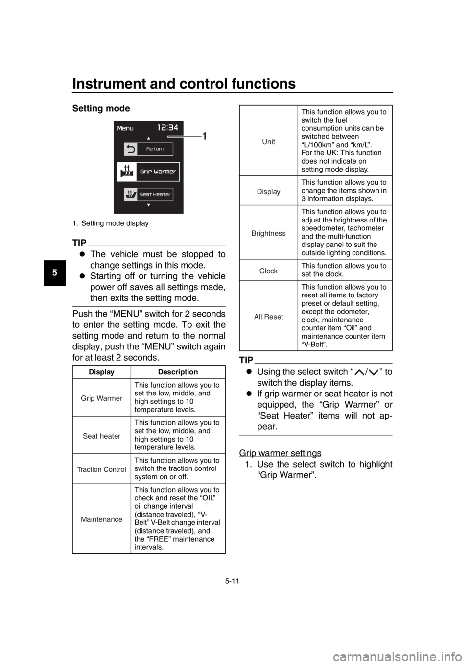
14 Setting mode
TIP
The vehicle must be stopped to
change settings in this mode.
Starting off or turning the vehicle
power off saves all settings made,
then exits the setting mode.
Push the “MENU” switch for 2 seconds
to enter the setting mode. To exit the
setting mode and return to the normal
display, push the “MENU” switch again
for at least 2 seconds.
TIP
Using the select switch “ / ” to
switch the display items.
If grip warmer or seat heater is not
equipped, the “Grip Warmer” or
“Seat Heater” items will not ap-
pear.
Grip warmer settings
1. Use the select switch to highlight “Grip Warmer”.
1. Setting mode display
Display Description This function allows you to
set the low, middle, and
high settings to 10
temperature levels.
This function allows you to
set the low, middle, and
high settings to 10
temperature levels.
This function allows you to
switch the traction control
system on or off.
This function allows you to
check and reset the “OIL”
oil change interval
(distance traveled), “V-
Belt” V-Belt change interval
(distance traveled), and
the “FREE” maintenance
intervals.
1
Grip Warmer
Seat heater
Traction Control
Maintenance
This function allows you to
switch the fuel
consumption units can be
switched between
“L/100km” and “km/L”.
For the UK: This function
does not indicate on
setting mode display.
This function allows you to
change the items shown in
3 information displays.
This function allows you to
adjust the brightness of the
speedometer, tachometer
and the multi-function
display panel to suit the
outside lighting conditions.
This function allows you to
set the clock.
This function allows you to
reset all items to factory
preset or default setting,
except the odometer,
clock, maintenance
counter item “Oil” and
maintenance counter item
“V-Belt”.
Unit
Display
Brightness
Clock
All Reset
BV1-28199-E0.book 11 ページ 2016年12月19日 月曜日 午前11時25分
Page 45 of 124
Instrument and control functions
5-12
1
2
3
4
5
6
7
8
9
10
11
12
13
14
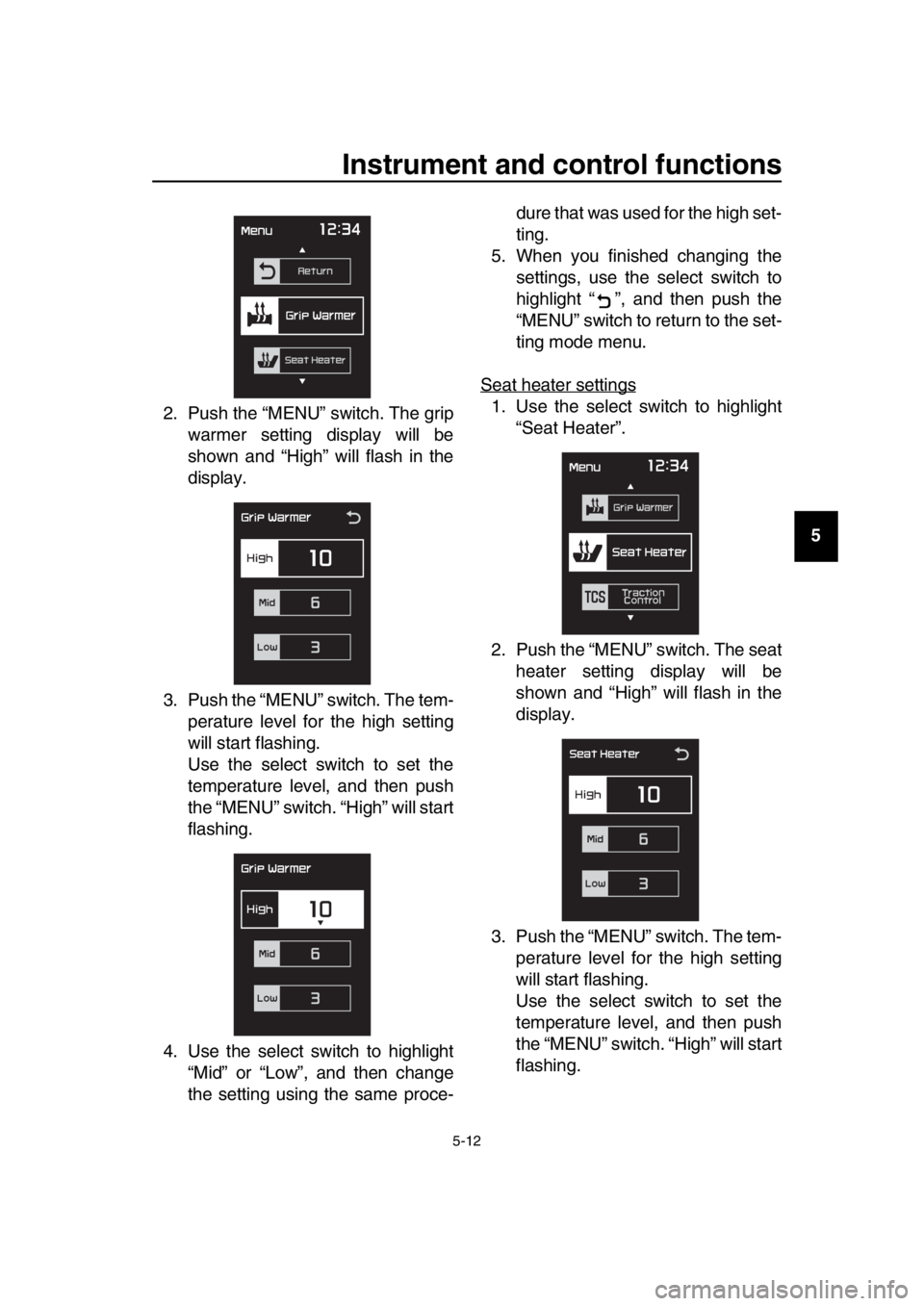
2. Push the “MENU” switch. The grip
warmer setting display will be
shown and “High” will flash in the
display.
3. Push the “MENU” switch. The tem- perature level for the high setting
will start flashing.
Use the select switch to set the
temperature level, and then push
the “MENU” switch. “High” will start
flashing.
4. Use the select switch to highlight “Mid” or “Low”, and then change
the setting using the same proce- dure that was used for the high set-
ting.
5. When you finished changing the settings, use the select switch to
highlight “ ”, and then push the
“MENU” switch to return to the set-
ting mode menu.
Seat heater settings
1. Use the select switch to highlight “Seat Heater”.
2. Push the “MENU” switch. The seat heater setting display will be
shown and “High” will flash in the
display.
3. Push the “MENU” switch. The tem- perature level for the high setting
will start flashing.
Use the select switch to set the
temperature level, and then push
the “MENU” switch. “High” will start
flashing.
BV1-28199-E0.book 12 ページ 2016年12月19日 月曜日 午前11時25分
Page 46 of 124
Instrument and control functions
5-13
1
2
3
4
5
6
7
8
9
10
11
12
13
14 4. Use the select switch to highlight
“Mid” or “Low”, and then change
the setting using the same proce-
dure that was used for the high set-
ting.
5. When you finished changing the settings, use the select switch to
highlight “ ”, and then push the
“MENU” switch to return to the set-
ting mode menu.
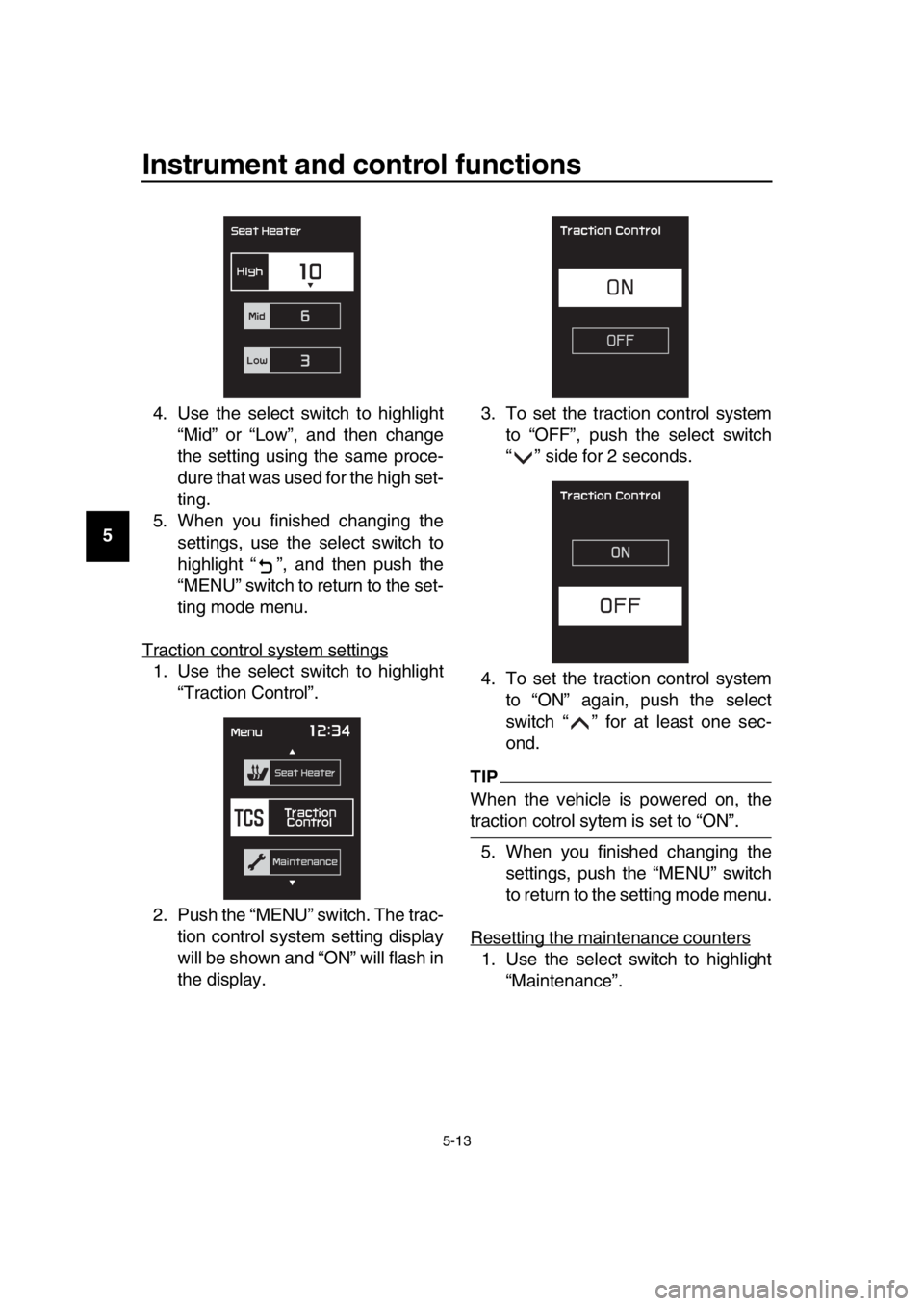
Traction control system settings
1. Use the select switch to highlight “Traction Control”.
2. Push the “MENU” switch. The trac- tion control system setting display
will be shown and “ON” will flash in
the display. 3. To set the traction control system
to “OFF”, push the select switch
“ ” side for 2 seconds.
4. To set the traction control system to “ON” again, push the select
switch “ ” for at least one sec-
ond.
TIP
When the vehicle is powered on, the
traction cotrol sytem is set to “ON”.
5. When you finished changing the settings, push the “MENU” switch
to return to the setting mode menu.
Resetting the maintenance counters
1. Use the select switch to highlight “Maintenance”.
BV1-28199-E0.book 13 ページ 2016年12月19日 月曜日 午前11時25分
Page 47 of 124
Instrument and control functions
5-14
1
2
3
4
5
6
7
8
9
10
11
12
13
14
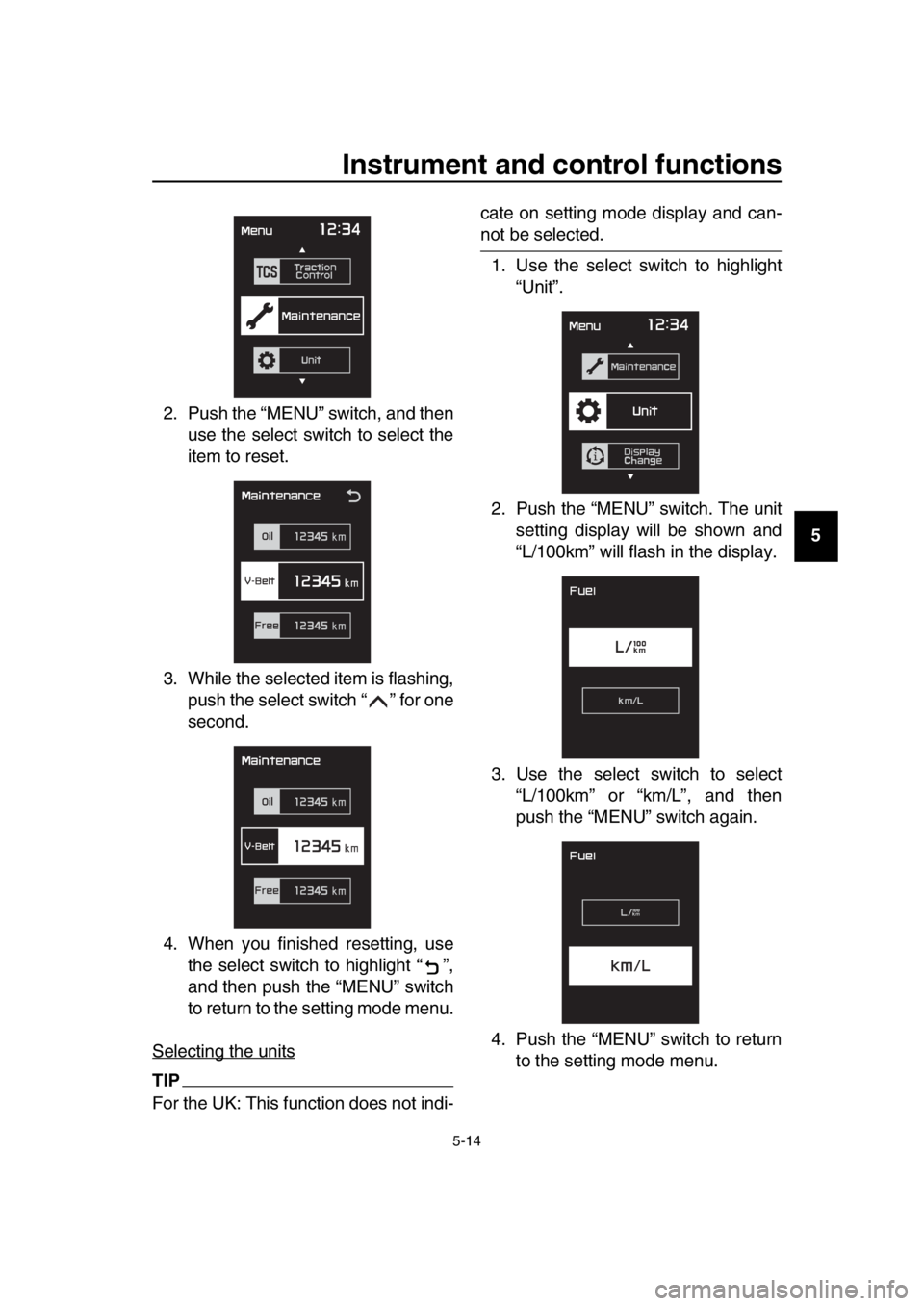
2. Push the “MENU” switch, and then
use the select switch to select the
item to reset.
3. While the selected item is flashing, push the select switch “ ” for one
second.
4. When you finished resetting, use the select switch to highlight “ ”,
and then push the “MENU” switch
to return to the setting mode menu.
Selecting the units
TIP
For the UK: This function does not indi- cate on setting mode display and can-
not be selected.
1. Use the select switch to highlight “Unit”.
2. Push the “MENU” switch. The unit setting display will be shown and
“L/100km” will flash in the display.
3. Use the select switch to select “L/100km” or “km/L”, and then
push the “MENU” switch again.
4. Push the “MENU” switch to return to the setting mode menu.
BV1-28199-E0.book 14 ページ 2016年12月19日 月曜日 午前11時25分
Page 48 of 124
Instrument and control functions
5-15
1
2
3
4
5
6
7
8
9
10
11
12
13
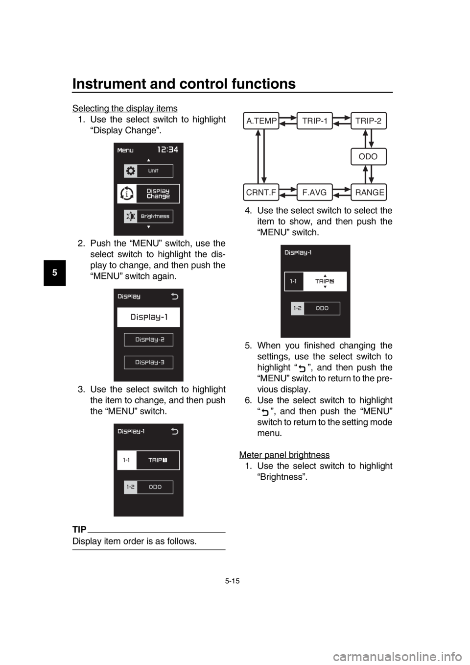
14 Selecting the display items
1. Use the select switch to highlight
“Display Change”.
2. Push the “MENU” switch, use the select switch to highlight the dis-
play to change, and then push the
“MENU” switch again.
3. Use the select switch to highlight the item to change, and then push
the “MENU” switch.
TIP
Display item order is as follows. 4. Use the select switch to select the
item to show, and then push the
“MENU” switch.
5. When you finished changing the settings, use the select switch to
highlight “ ”, and then push the
“MENU” switch to return to the pre-
vious display.
6. Use the select switch to highlight “ ”, and then push the “MENU”
switch to return to the setting mode
menu.
Meter panel brightness
1. Use the select switch to highlight “Brightness”.
A.TEMP TRIP-1 TRIP-2
ODO
CRNT.F F.AVG RANGE
BV1-28199-E0.book 15 ページ 2016年12月19日 月曜日 午前11時25分
Page 49 of 124

Instrument and control functions
5-16
1
2
3
4
5
6
7
8
9
10
11
12
13
14
2. Push the “MENU” switch.
3. Use the select switch to select the
desired brightness level.
4. Push the “MENU” switch to return to the setting mode menu.
Setting the clock
TIP
The clock uses a 12-hour time system. 1. Use the select switch to highlight “Clock”.
2. Push the “MENU” switch.
3. When the hour digits start flashing, use the select switch to set the
hours.
4. Push the “MENU” switch, and the minute digits start flashing.
5. Use the select switch to set the minutes.
6. Push the “MENU” switch to return to the setting mode menu.
Resetting all of the display items
1. Use the select switch to highlight “All Reset”.
2. Push the “MENU” switch.
3. Use the select switch to highlight
BV1-28199-E0.book 16 ページ 2016年12月19日 月曜日 午前11時25分
Page 50 of 124
Instrument and control functions
5-17
1
2
3
4
5
6
7
8
9
10
11
12
13
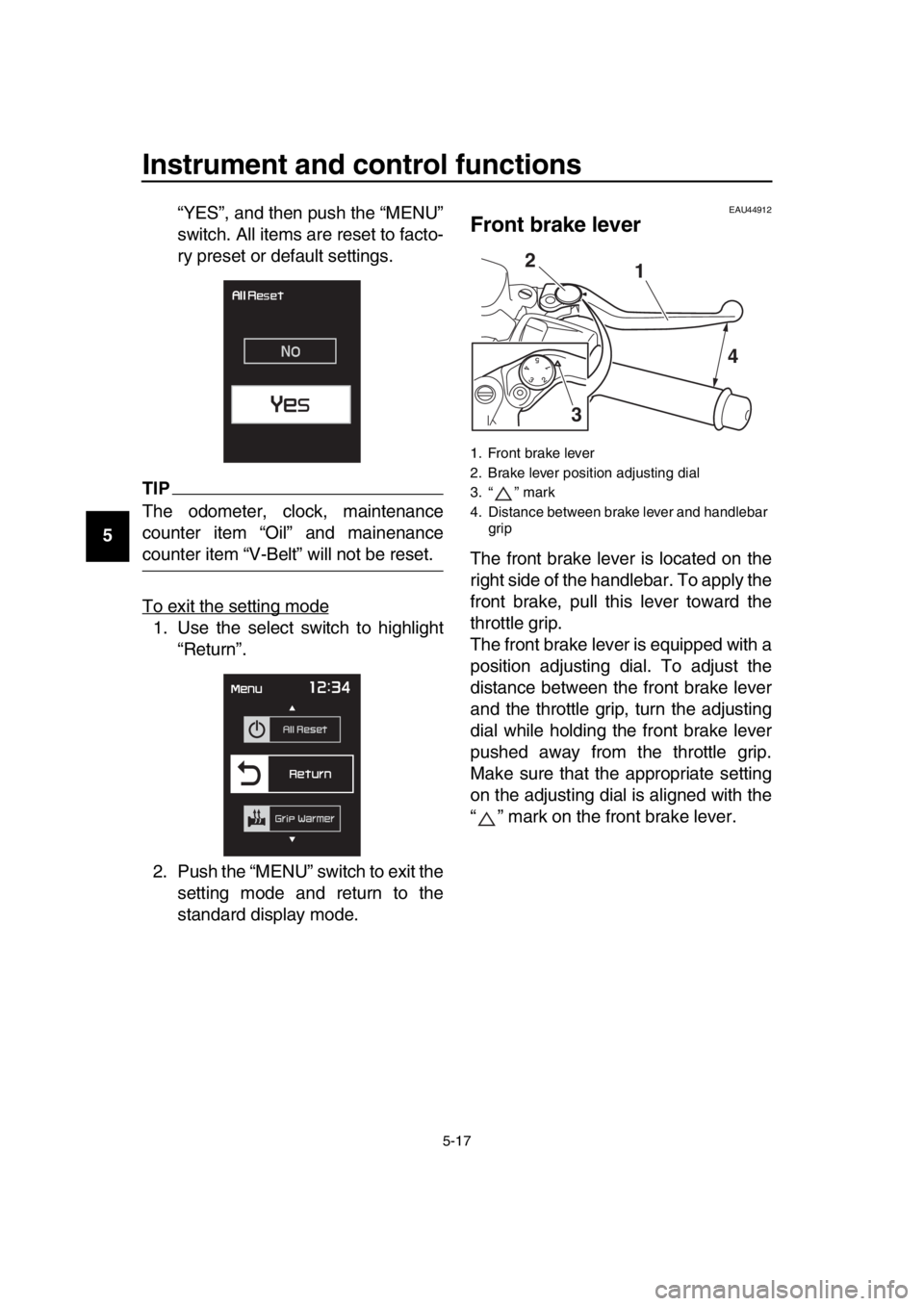
14 “YES”, and then push the “MENU”
switch. All items are reset to facto-
ry preset or default settings.
TIP
The odometer, clock, maintenance
counter item “Oil” and mainenance
counter item “V-Belt” will not be reset.
To exit the setting mode
1. Use the select switch to highlight
“Return”.
2. Push the “MENU” switch to exit the setting mode and return to the
standard display mode.
EAU44912
Front brake lever
The front brake lever is located on the
right side of the handlebar. To apply the
front brake, pull this lever toward the
throttle grip.
The front brake lever is equipped with a
position adjusting dial. To adjust the
distance between the front brake lever
and the throttle grip, turn the adjusting
dial while holding the front brake lever
pushed away from the throttle grip.
Make sure that the appropriate setting
on the adjusting dial is aligned with the
“ ” mark on the front brake lever.
1. Front brake lever
2. Brake lever position adjusting dial
3. “ ” mark
4. Distance between brake lever and handlebar grip
1
2
3 4
BV1-28199-E0.book 17 ページ 2016年12月19日 月曜日 午前11時25分
Page 121 of 124

12-1
1
2
3
4
5
6
7
8
9
10
11
12
13
14
Index
A
ABS .......................................................5-19
ABS warning light ....................................5-3
Acceleration and deceleration .................7-3
Air filter element, replacing ....................8-15
Auxiliary DC jack ...................................5-28
B
Battery ...................................................8-28
Brake fluid, changing .............................8-24
Brake fluid level, checking .....................8-23
Brake lever, front ...................................5-17
Brake lever, rear ....................................5-18
Brake levers, lubricating ........................8-26
Braking ....................................................7-4
C
Cables, checking and lubricating...........8-25
Canister .................................................8-10
Care.........................................................9-1
Catalytic converter.................................5-23
Centerstand and sidestand, checking and lubricating.....................................8-26
Coolant ..................................................8-14
Cruise control indicator lights ..................5-2
Cruise control switches ...........................5-2
Cruise control system (XP530D-A) .........4-1
D
Data recording, vehicle..........................11-2
Diagnostic connector .............................11-2
Dimmer/Pass switch ................................5-1
D-mode (drive mode)
(XP530-A, XP530D-A) ..........................4-3
Drive belt slack ......................................8-24
Drive mode switch ...................................5-2
E
Emergency mode ..................................8-37
Engine break-in .......................................7-5
Engine idling speed, checking ...............8-16
Engine oil and oil filter cartridge ............8-10
Engine serial number ............................11-1
Engine stop switch ..................................5-1
Engine trouble warning light ....................5-2
F
Front and rear brake lever free play, checking ..............................................8-20
Front and rear brake pads, checking.....8-22
Front fork, checking ...............................8-27
Fuel .......................................................5-21
Fuel consumption, tips for reducing ........7-5
Fuel tank cap .........................................5-20
Fuel tank overflow hose ........................5-22 Fuses, replacing.................................... 8-30
H
Handlebar switches................................. 5-1
Hazard switch ......................................... 5-1
High beam indicator light ........................ 5-2
Horn switch ............................................. 5-1
How to lock the centerstand.................. 3-10
How to lock the steering.......................... 3-9
I
Identification numbers ........................... 11-1
Ignition circuit cut-off system................. 5-30
Indicator lights and warning lights ........... 5-2
K
Key, handling of smart and mechanical
key ........................................................ 3-3
L
License plate light bulb, replacing ......... 8-33
M
Maintenance and lubrication, periodic .... 8-4
Maintenance, emission control system ... 8-3
Matte color, caution................................. 9-1
Menu switch ............................................ 5-2
Model label............................................ 11-1
Multi-function display .............................. 5-5
O
ON/Start switch ....................................... 5-1
Operating range of the smart key system .................................................. 3-2
P
Panels, removing and installing .............. 8-7
Parking .................................................... 7-6
Parking mode ........................................ 3-12
Part locations .......................................... 2-1
Powering off the vehicle .......................... 3-8
Powering on the vehicle .......................... 3-7
R
Rear brake lock cable, adjusting ........... 8-21
Rear brake lock, checking..................... 8-22
Rear brake lock lever ............................ 5-18
Rear view mirrors .................................. 5-26
S
Safe-riding points .................................... 1-5
Safety information ................................... 1-1
Select switch ........................................... 5-2
Shock absorber assembly..................... 5-27
Sidestand .............................................. 5-29
Smart key ................................................ 3-5
Smart key battery, replacing ................... 3-6
Smart key system ................................... 3-1
Smart key system indicator light ............. 5-3
BV1-28199-E0.book 1 ページ 2016年12月19日 月曜日 午前11時25分