BRAKE PEDAL YAMAHA TRICITY 300 2020 Owners Manual
[x] Cancel search | Manufacturer: YAMAHA, Model Year: 2020, Model line: TRICITY 300, Model: YAMAHA TRICITY 300 2020Pages: 114, PDF Size: 11.27 MB
Page 8 of 114
Table of contentsSafety information ............................ 1-1
Further safe-riding points ............... 1-5
Description ....................................... 2-1
Left view ......................................... 2-1
Right view ....................................... 2-2
Controls and instruments ............... 2-3
Smart key system ........................... 3-1
Smart key system ........................... 3-1
Operating range of the smart key system......................................... 3-2
Handling of the smart key and mechanical keys ......................... 3-3
Smart key ....................................... 3-4
Replacing the smart key battery..... 3-6
Main switch .................................... 3-7
Stan din g assist ................................. 4-1
Standing assist ............................... 4-1
Instrument an d control functions ... 5-1
Indicator lights and warning
lights............................................ 5-1
Multi-function meter unit ................ 5-3
Handlebar switches ........................ 5-8
Front brake lever .......................... 5-10
Brake pedal .................................. 5-10
Rear brake lever ........................... 5-11
Parking brake lever ....................... 5-12
ABS .............................................. 5-12 Traction control system ................ 5-13
Fuel tank cap ................................ 5-15
Fuel ............................................... 5-16
Fuel tank overflow hose ................ 5-18
Catalytic converter ........................ 5-18
Storage compartment ................... 5-18
Adjusting the shock absorber
assemblies ................................. 5-20
Auxiliary DC jack ........................... 5-20
Sidestand ...................................... 5-21
Ignition circuit cut-off system ....... 5-22
For your safety – pre-operation
checks ............................................... 6-1
Operation an d important ri din g
points ................................................. 7-1
Engine break-in ............................... 7-1
Starting the engine .......................... 7-2
Starting off ...................................... 7-3
Acceleration and deceleration ........ 7-3
Braking ............................................ 7-3
Tips for reducing fuel consumption ................................ 7-4
Parking ............................................ 7-4
Perio dic maintenance an d
a d justment ........................................ 8-1
Tool kit ............................................ 8-2
Periodic maintenance charts .......... 8-3 Periodic maintenance chart for the
emission control system ............. 8-3
General maintenance and lubrication chart .......................... 8-4
Removing and installing the
panel............................................ 8-9
Checking the spark plug............... 8-10
Canister ........................................ 8-11
Engine oil and oil filter element..... 8-12
Why Yamalube.............................. 8-14
Final transmission oil .................... 8-14
Coolant ......................................... 8-15
Air filter and V-belt case air filter elements .................................... 8-17
Checking the throttle grip free play ............................................ 8-21
Valve clearance............................. 8-21
Tires .............................................. 8-22
Cast wheels .................................. 8-23
Checking the front brake lever
free play..................................... 8-24
Checking the rear brake lever free play..................................... 8-24
Checking the parking brake ......... 8-25
Checking the front and rear brake pads ................................ 8-25
Checking the brake fluid level ...... 8-26
Changing the brake fluid .............. 8-27
Checking the V-belt ...................... 8-27
Checking and lubricating the cables ........................................ 8-28UBX9E0E0.book Page 1 Monday, January 20, 2020 10:54 AM
Page 9 of 114
Table of contents
Checking and lubricating the
throttle grip and cable ................8-28
Lubricating the front and rear brake levers................................8-28
Checking and lubricating the
brake pedal ................................8-29
Checking and lubricating the centerstand and sidestand ........8-29
Checking the front fork..................8-30
Checking the steering ...................8-31
Lubricating the steering bearings .....................................8-31
Checking the wheel bearings ........8-31
Battery ...........................................8-32
Replacing the fuses .......................8-33
Vehicle lights .................................8-35
Replacing a turn signal light bulb ............................................8-35
Replacing the license plate light bulb ............................................8-36
Troubleshooting ............................8-36
Troubleshooting chart ...................8-38
Emergency mode .........................8-40
Vehicle care an d stora ge .................9-1
Matte color caution .........................9-1
Care .................................................9-1
Storage ............................................9-3 Specifications
................................. 10-1
Consumer information ................... 11-1
Identification numbers .................. 11-1
Diagnostic connector.................... 11-2
Vehicle data recording .................. 11-2
In dex ................................................ 12-1
UBX9E0E0.book Page 2 Monday, January 20, 2020 10:54 AM
Page 17 of 114
Description
2-2
2
EAU10421
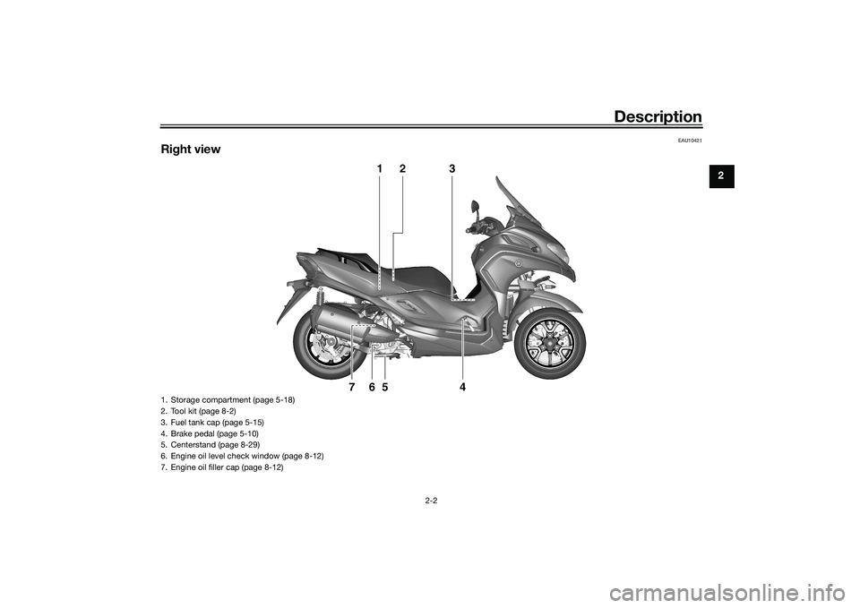
Right view
1
2
3
4
5
6
7
1. Storage compartment (page 5-18)
2. Tool kit (page 8-2)
3. Fuel tank cap (page 5-15)
4. Brake pedal (page 5-10)
5. Centerstand (page 8-29)
6. Engine oil level check window (page 8-12)
7. Engine oil filler cap (page 8-12)
UBX9E0E0.book Page 2 Monday, January 20, 2020 10:54 AM
Page 41 of 114
Instrument and control functions
5-10
5
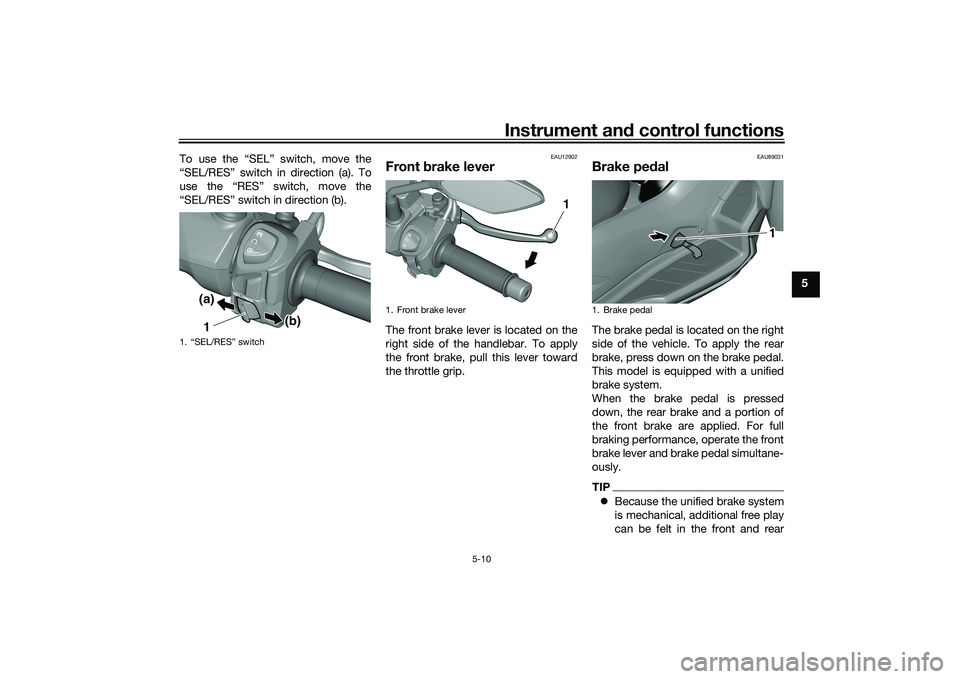
To use the “SEL” switch, move the
“SEL/RES” switch in direction (a). To
use the “RES” switch, move the
“SEL/RES” switch in direction (b).
EAU12902
Front
brake leverThe front brake lever is located on the
right side of the handlebar. To apply
the front brake, pull this lever toward
the throttle grip.
EAU89031
Brake pe dalThe brake pedal is located on the right
side of the vehicle. To apply the rear
brake, press down on the brake pedal.
This model is equipped with a unified
brake system.
When the brake pedal is pressed
down, the rear brake and a portion of
the front brake are applied. For full
braking performance, operate the front
brake lever and brake pedal simultane-
ously.TIP Because the unified brake system
is mechanical, additional free play
can be felt in the front and rear
1. “SEL/RES” switch
1(a)
(b)
1. Front brake lever
1
1. Brake pedal
1
UBX9E0E0.book Page 10 Monday, January 20, 2020 10:54 AM
Page 42 of 114
Instrument and control functions
5-11
5 brake levers when the brake pedal
is pressed down, but this does not
indicate a malfunction.
The unified brake system does not
operate when the front brake lever
is being pulled directly.
EAU89350
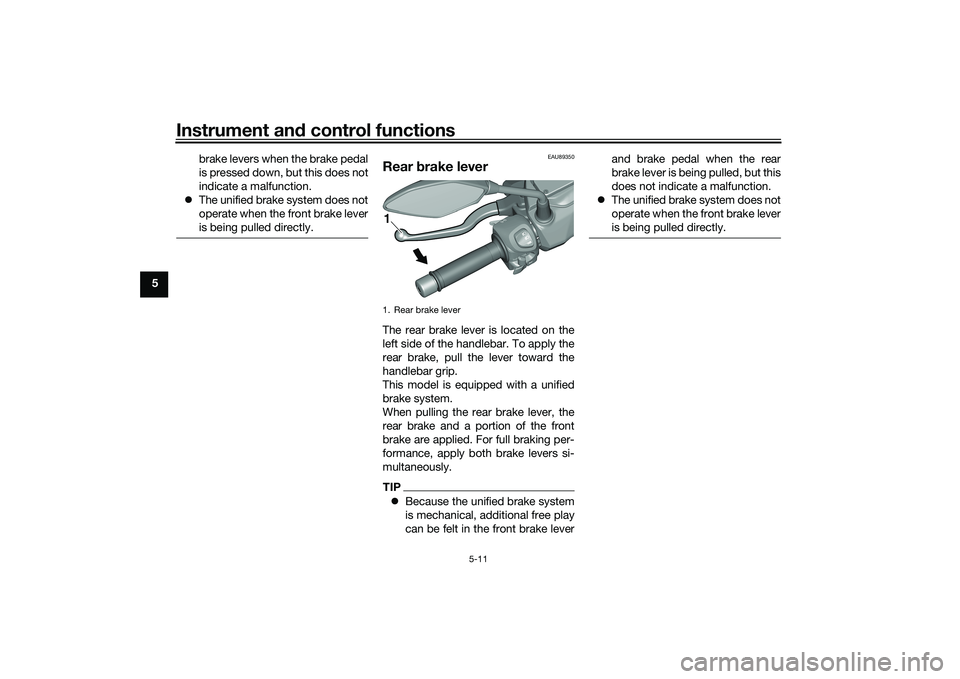
Rear brake leverThe rear brake lever is located on the
left side of the handlebar. To apply the
rear brake, pull the lever toward the
handlebar grip.
This model is equipped with a unified
brake system.
When pulling the rear brake lever, the
rear brake and a portion of the front
brake are applied. For full braking per-
formance, apply both brake levers si-
multaneously.TIP Because the unified brake system
is mechanical, additional free play
can be felt in the front brake lever and brake pedal when the rear
brake lever is being pulled, but this
does not indicate a malfunction.
The unified brake system does not
operate when the front brake lever
is being pulled directly.1. Rear brake lever1
UBX9E0E0.book Page 11 Monday, January 20, 2020 10:54 AM
Page 43 of 114
Instrument and control functions
5-12
5
EAU89340
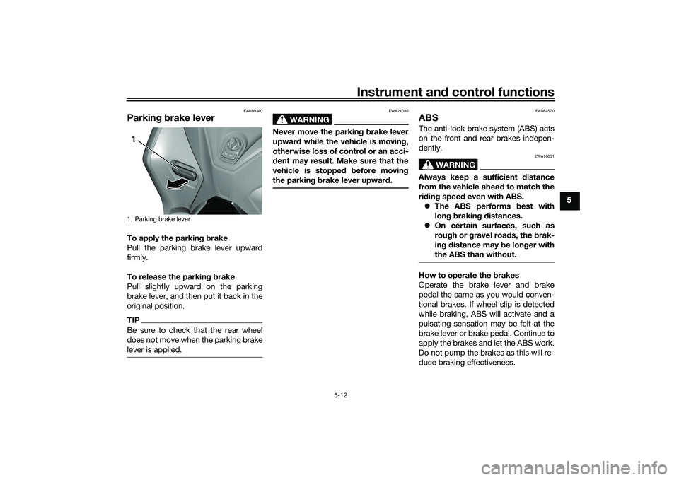
Parkin g b rake leverTo apply the parkin g b rake
Pull the parking brake lever upward
firmly.
To release the parkin g b rake
Pull slightly upward on the parking
brake lever, and then put it back in the
original position.TIPBe sure to check that the rear wheel
does not move when the parking brake
lever is applied.
WARNING
EWA21030
Never move the parkin g b rake lever
upwar d while the vehicle is movin g,
otherwise loss of control or an acci-
d ent may result. Make sure that the
vehicle is stopped before movin g
the parkin g b rake lever upwar d.
EAU84570
ABSThe anti-lock brake system (ABS) acts
on the front and rear brakes indepen-
dently.
WARNING
EWA16051
Always keep a sufficient d istance
from the vehicle ahea d to match the
ri din g speed even with ABS.
The ABS performs b est with
lon g b rakin g d istances.
On certain surfaces, such as
rou gh or g ravel roa ds, the b rak-
in g d istance may be lon ger with
the ABS than without.How to operate the brakes
Operate the brake lever and brake
pedal the same as you would conven-
tional brakes. If wheel slip is detected
while braking, ABS will activate and a
pulsating sensation may be felt at the
brake lever or brake pedal. Continue to
apply the brakes and let the ABS work.
Do not pump the brakes as this will re-
duce braking effectiveness.
1. Parking brake lever1
UBX9E0E0.book Page 12 Monday, January 20, 2020 10:54 AM
Page 44 of 114
Instrument and control functions
5-13
5
The ABS performs a self-check
when you first start off. During this
time a clicking noise from the hy-
draulic unit may be audible, and if
the brake lever or brake pedal is
applied a vibration can be felt, but
this is not a malfunction.
The brake system will revert to a
conventional brake system in case
of ABS malfunction.
NOTICE
ECA20100
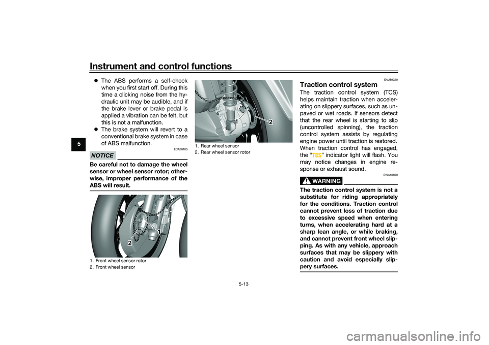
Be careful not to damag e the wheel
sensor or wheel sensor rotor; other-
wise, improper performance of the
ABS will result.
EAU89320
Traction control systemThe traction control system (TCS)
helps maintain traction when acceler-
ating on slippery surfaces, such as un-
paved or wet roads. If sensors detect
that the rear wheel is starting to slip
(uncontrolled spinning), the traction
control system assists by regulating
engine power until traction is restored.
When traction control has engaged,
the “ ” indicator light will flash. You
may notice changes in engine re-
sponse or exhaust sound.
WARNING
EWA18860
The traction control system is not a
su bstitute for rid ing appropriately
for the con ditions. Traction control
cannot prevent loss of traction due
to excessive speed when entering
turns, when acceleratin g har d at a
sharp lean an gle, or while brakin g,
an d cannot prevent front wheel slip-
pin g. As with any vehicle, approach
surfaces that may be slippery with
caution an d avoi d especially slip-
pery surfaces.
1. Front wheel sensor rotor
2. Front wheel sensor
1
2
1. Rear wheel sensor
2. Rear wheel sensor rotor
1 2
2 2
UBX9E0E0.book Page 13 Monday, January 20, 2020 10:54 AM
Page 56 of 114
For your safety – pre-operation checks
6-2
6
Rear brake • Check operation.
• If soft or spongy, have Yamaha dealer bleed hydraulic system.
• Check brake pads for wear.
• Replace if necessary.
• Check fluid level in reservoir.
• If necessary, add specified brake fluid to specified level.
• Check hydraulic system for leakage. 8-25, 8-26
Throttle g rip • Make sure that operation is smooth.
• Check throttle grip free play.
• If necessary, have Yamaha dealer adjust throttle grip free play and lubricate ca-
ble and grip housing. 8-21, 8-28
Control ca bles • Make sure that operation is smooth.
• Lubricate if necessary. 8-28
Wheels an d tires •Check for damage.
• Check tire condition and tread depth.
• Check air pressure.
• Correct if necessary. 8-22, 8-23
Brake ped al • Make sure that operation is smooth.
• Lubricate pedal pivoting point if necessary.
8-29
Brake levers • Make sure that operation is smooth.
• Lubricate lever pivoting points if necessary.
8-28
Centerstan d, si destan d • Make sure that operation is smooth.
• Lubricate pivots if necessary. 8-29
Chassis fasteners • Make sure that all nuts, bolts and screws are properly tightened.
• Tighten if necessary.
—
Instruments, li ghts, si gnals
an d switches • Check operation.
• Correct if necessary.
—
Si destan d switch • Check operation of ignition circuit cut-off system.
• If system is not working correctly, have Yamaha dealer check vehicle. 5-21
ITEM
CHECKS PAGE
UBX9E0E0.book Page 2 Monday, January 20, 2020 10:54 AM
Page 66 of 114
Periodic maintenance an d a djustment
8-6
8
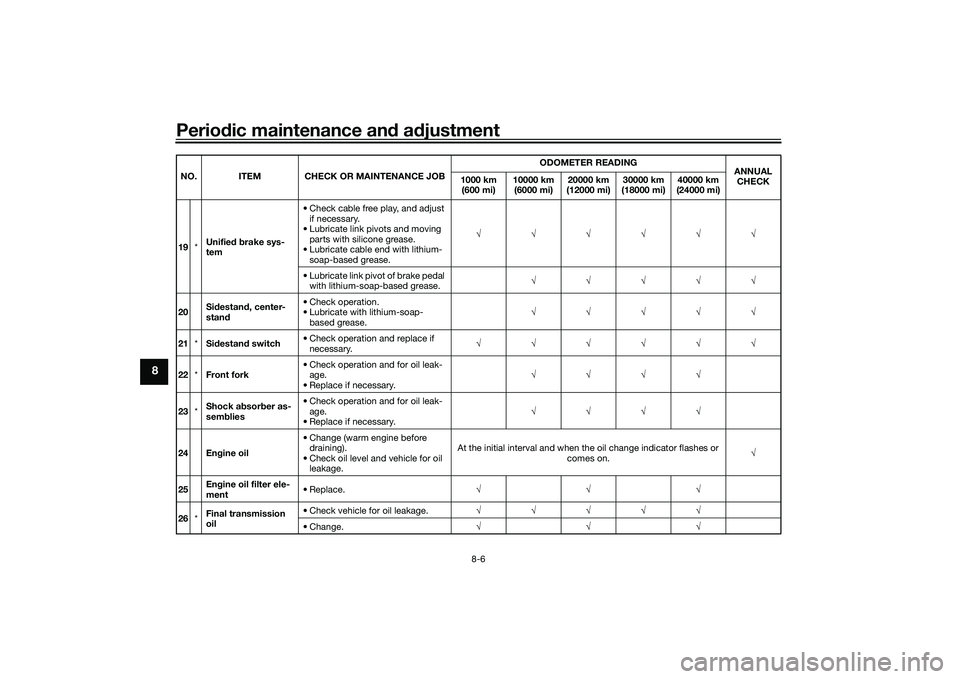
19 *Unifie
d b rake sys-
tem • Check cable free play, and adjust
if necessary.
• Lubricate link pivots and moving parts with silicone grease.
• Lubricate cable end with lithium- soap-based grease. √√√√√√
• Lubricate link pivot of brake pedal with lithium-soap-based grease. √√√√√
20 Si
destan d, center-
stan d • Check operation.
• Lubricate with lithium-soap-
based grease. √√√√√
21 *Sidestan d switch • Check operation and replace if
necessary. √√√√√√
22 *Front fork • Check operation and for oil leak-
age.
• Replace if necessary. √√√√
23 *Shock a
bsor ber as-
sem blies • Check operation and for oil leak-
age.
• Replace if necessary. √√√√
24 En gine oil • Change (warm engine before
draining).
• Check oil level and vehicle for oil leakage. At the initial interval and when the oil change indicator flashes or
comes on. √
25 En
gine oil filter ele-
ment • Replace.
√√√
26 *Final transmission
oil • Check vehicle for oil leakage.
√√√√√
• Change. √√√
NO. ITEM CHECK OR MAINTENANCE JOB
ODOMETER READING
ANNUAL
CHECK
1000 km
(600 mi) 10000 km
(6000 mi) 20000 km
(12000 mi) 30000 km
(18000 mi) 40000 km
(24000 mi)UBX9E0E0.book Page 6 Monday, January 20, 2020 10:54 AM
Page 89 of 114
Periodic maintenance an d a djustment
8-29
8
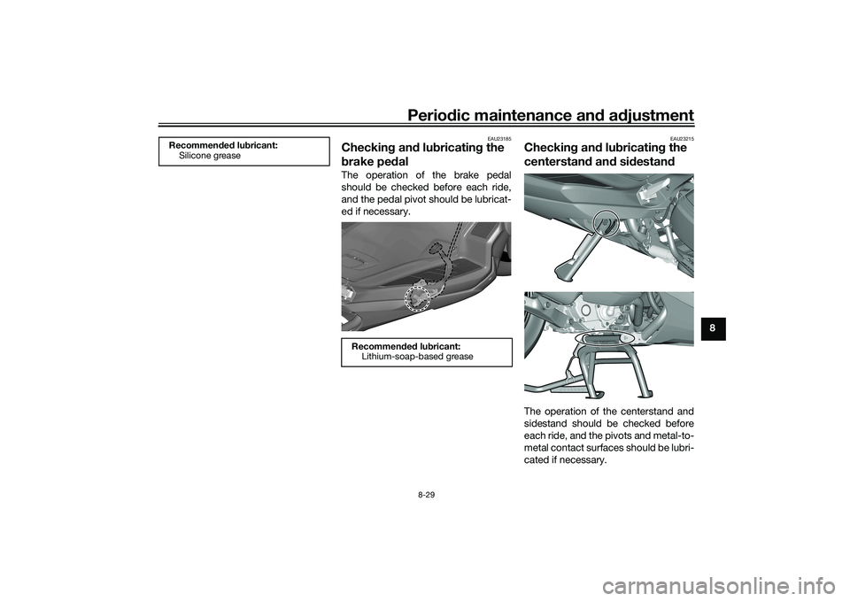
EAU23185
Checkin g an d lu bricatin g the
b rake pe dalThe operation of the brake pedal
should be checked before each ride,
and the pedal pivot should be lubricat-
ed if necessary.
EAU23215
Checkin g an d lu bricatin g the
centerstan d an d si destan dThe operation of the centerstand and
sidestand should be checked before
each ride, and the pivots and metal-to-
metal contact surfaces should be lubri-
cated if necessary.
Recommen ded lu bricant:
Silicone grease
Recommen ded lu bricant:
Lithium-soap-based grease
UBX9E0E0.book Page 29 Monday, January 20, 2020 10:54 AM