YAMAHA TTR90 2001 Owners Manual
Manufacturer: YAMAHA, Model Year: 2001, Model line: TTR90, Model: YAMAHA TTR90 2001Pages: 288, PDF Size: 15.39 MB
Page 221 of 288
4 - 37
ENG
POMPE A HUILE
ÖLPUMPE
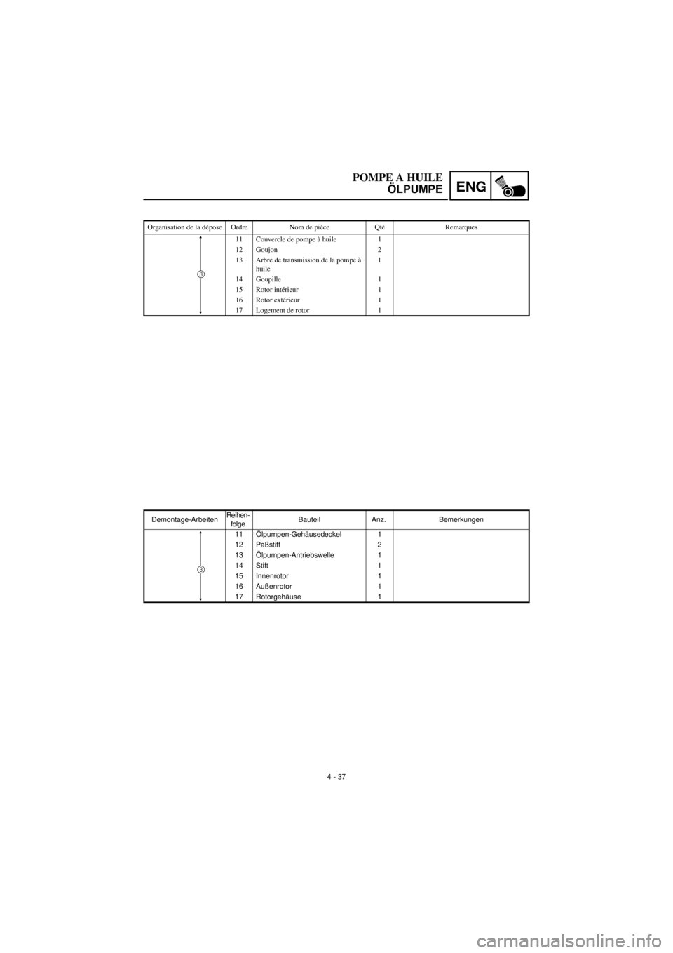
Demontage-ArbeitenReihen-
folgeBauteil Anz. Bemerkungen
11 Ölpumpen-Gehäusedeckel 1
12 Paßstift 2
13 Ölpumpen-Antriebswelle 1
14 Stift 1
15 Innenrotor 1
16 Außenrotor 1
17 Rotorgehäuse 1
3
Organisation de la dépose Ordre Nom de pièce Qté Remarques
11 Couvercle de pompe à huile 1
12 Goujon 2
13 Arbre de transmission de la pompe à
huile1
14 Goupille 1
15 Rotor intérieur 1
16 Rotor extérieur 1
17 Logement de rotor 1
3
Page 222 of 288
4 - 38
ENGOIL PUMP
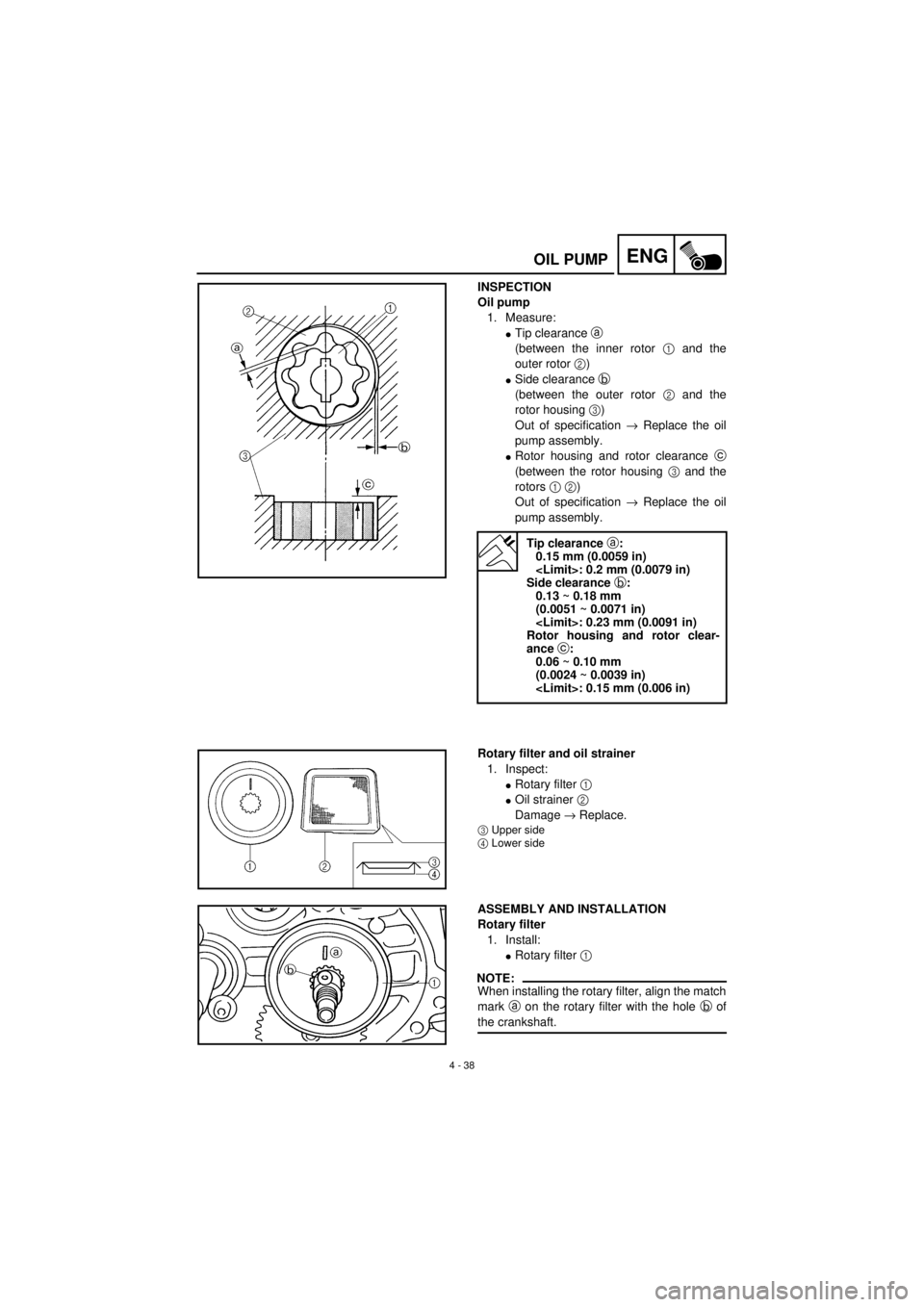
INSPECTION
Oil pump
1. Measure:
lTip clearance a
(between the inner rotor 1 and the
outer rotor 2)
lSide clearance b
(between the outer rotor 2 and the
rotor housing 3)
Out of specification ® Replace the oil
pump assembly.
lRotor housing and rotor clearance c
(between the rotor housing 3 and the
rotors 1 2)
Out of specification ® Replace the oil
pump assembly.
Tip clearance a:
0.15 mm (0.0059 in)
Side clearance b:
0.13 ~ 0.18 mm
(0.0051 ~ 0.0071 in)
Rotor housing and rotor clear-
ance c:
0.06 ~ 0.10 mm
(0.0024 ~ 0.0039 in)
Rotary filter and oil strainer
1. Inspect:
lRotary filter 1
lOil strainer 2
Damage ® Replace.
3Upper side
4Lower side
ASSEMBLY AND INSTALLATION
Rotary filter
1. Install:
lRotary filter 1
NOTE:
When installing the rotary filter, align the match
mark a on the rotary filter with the hole b of
the crankshaft.
Page 223 of 288
4 - 38
ENG
POMPE A HUILE
ÖLPUMPE
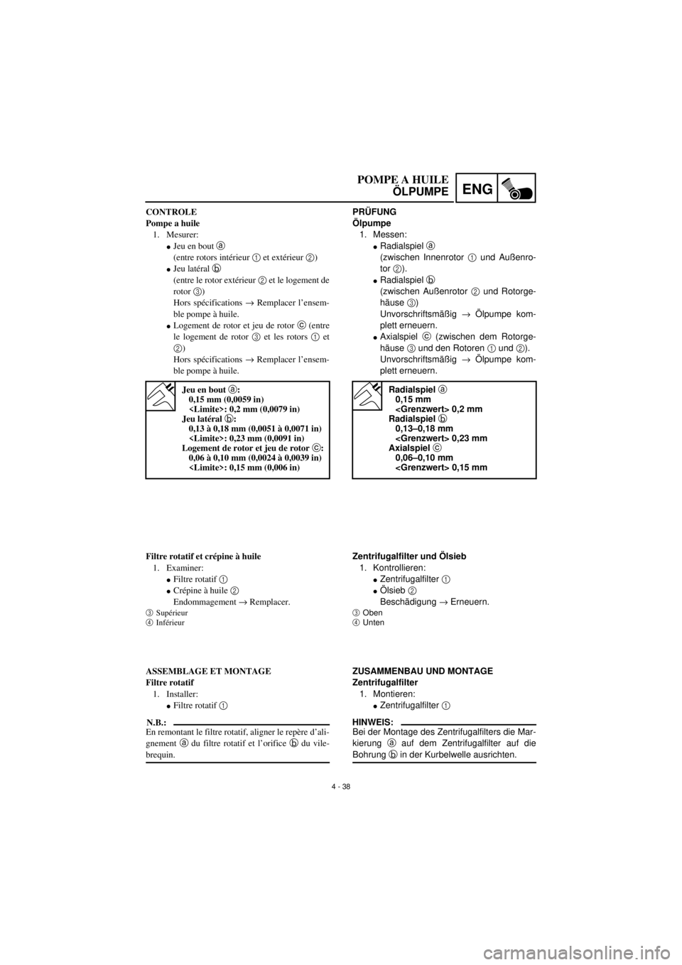
PRÜFUNG
Ölpumpe
1. Messen:
lRadialspiel a
(zwischen Innenrotor 1 und Außenro-
tor 2).
lRadialspiel b
(zwischen Außenrotor 2 und Rotorge-
häuse 3)
Unvorschriftsmäßig ® Ölpumpe kom-
plett erneuern.
lAxialspiel c (zwischen dem Rotorge-
häuse 3 und den Rotoren 1 und 2).
Unvorschriftsmäßig ® Ölpumpe kom-
plett erneuern.
Radialspiel a
0,15 mm
Radialspiel b
0,13–0,18 mm
Axialspiel c
0,06–0,10 mm
Zentrifugalfilter und Ölsieb
1. Kontrollieren:
lZentrifugalfilter 1
lÖlsieb 2
Beschädigung ® Erneuern.
3Oben
4Unten
ZUSAMMENBAU UND MONTAGE
Zentrifugalfilter
1. Montieren:
lZentrifugalfilter 1
HINWEIS:
Bei der Montage des Zentrifugalfilters die Mar-
kierung a auf dem Zentrifugalfilter auf die
Bohrung b in der Kurbelwelle ausrichten. CONTROLE
Pompe a huile
1. Mesurer:
lJeu en bout a
(entre rotors intérieur 1 et extérieur 2)
lJeu latéral b
(entre le rotor extérieur 2 et le logement de
rotor 3)
Hors spécifications ® Remplacer l’ensem-
ble pompe à huile.
lLogement de rotor et jeu de rotor c (entre
le logement de rotor 3 et les rotors 1 et
2)
Hors spécifications ® Remplacer l’ensem-
ble pompe à huile.
Jeu en bout a:
0,15 mm (0,0059 in)
Jeu latéral b:
0,13 à 0,18 mm (0,0051 à 0,0071 in)
Logement de rotor et jeu de rotor c:
0,06 à 0,10 mm (0,0024 à 0,0039 in)
Filtre rotatif et crépine à huile
1. Examiner:
lFiltre rotatif 1
lCrépine à huile 2
Endommagement ® Remplacer.
3Supérieur
4Inférieur
ASSEMBLAGE ET MONTAGE
Filtre rotatif
1. Installer:
lFiltre rotatif 1
N.B.:
En remontant le filtre rotatif, aligner le repère d’ali-
gnement a du filtre rotatif et l’orifice b du vile-
brequin.
Page 224 of 288
4 - 39
ENGCDI MAGNETO
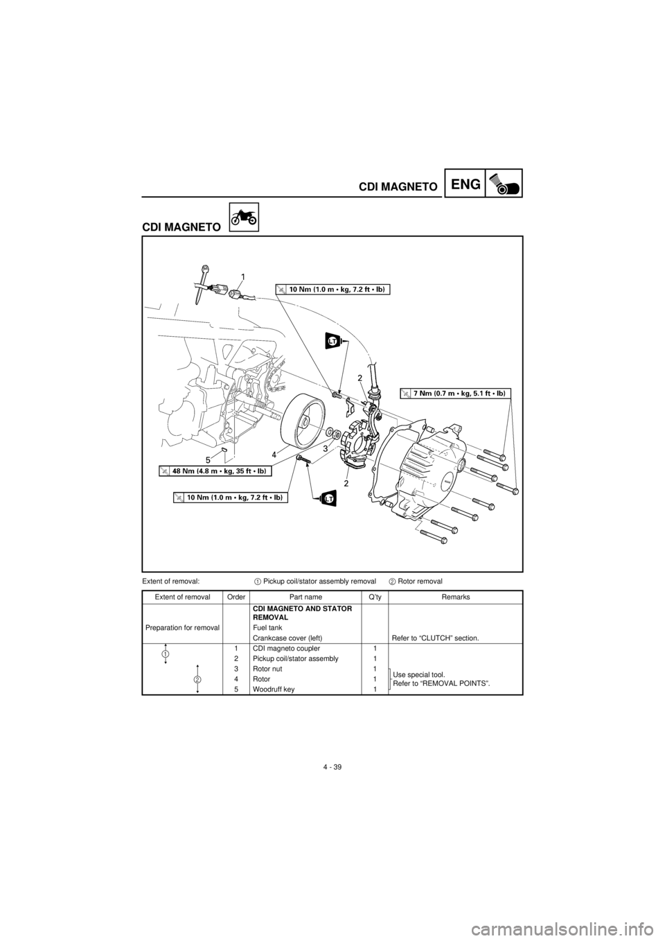
CDI MAGNETO
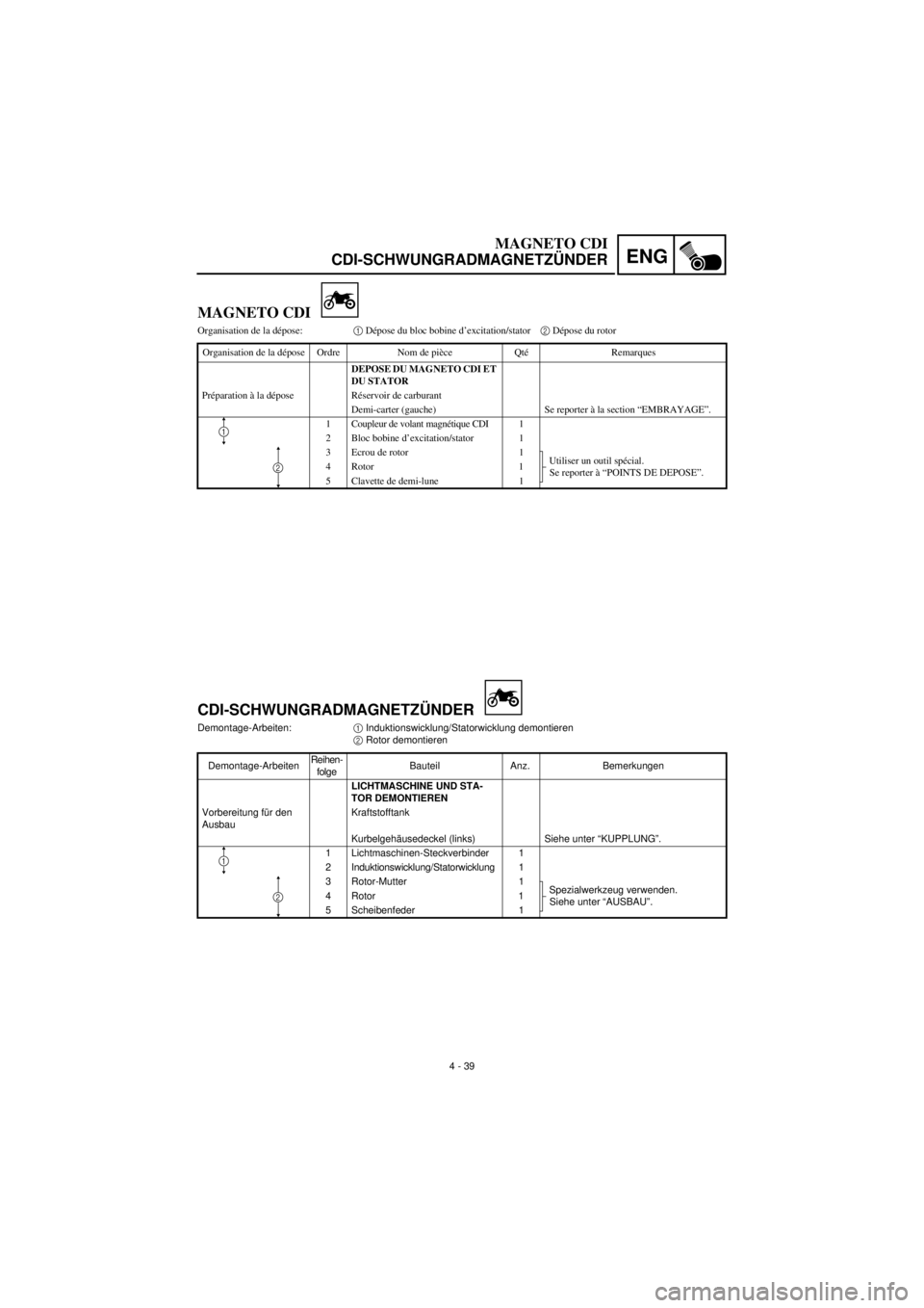
Extent of removal:1 Pickup coil/stator assembly removal2 Rotor removal
Extent of removal Order Part name Q’ty Remarks
CDI MAGNETO AND STATOR
REMOVAL
Preparation for removal Fuel tank
Crankcase cover (left) Refer to “CLUTCH” section.
1 CDI magneto coupler 1
2 Pickup coil/stator assembly 1
3 Rotor nut 1
Use special tool.
Refer to “REMOVAL POINTS”. 4 Rotor 1
5 Woodruff key 1
1
2
Page 225 of 288
4 - 39
ENG
MAGNETO CDI
CDI-SCHWUNGRADMAGNETZÜNDER
CDI-SCHWUNGRADMAGNETZÜNDER
Demontage-Arbeiten:1 Induktionswicklung/Statorwicklung demontieren
2 Rotor demontieren
Demontage-ArbeitenReihen-
folgeBauteil Anz. Bemerkungen
LICHTMASCHINE UND STA-
TOR DEMONTIEREN
Vorbereitung für den
AusbauKraftstofftank
Kurbelgehäusedeckel (links) Siehe unter “KUPPLUNG”.
1 Lichtmaschinen-Steckverbinder 1
2 Induktionswicklung/Statorwicklung 1
3 Rotor-Mutter 1
Spezialwerkzeug verwenden.
Siehe unter “AUSBAU”. 4 Rotor 1
5 Scheibenfeder 1
1
2
MAGNETO CDI
Organisation de la dépose:1 Dépose du bloc bobine d’excitation/stator2 Dépose du rotor
Organisation de la dépose Ordre Nom de pièce Qté Remarques
DEPOSE DU MAGNETO CDI ET
DU STATOR
Préparation à la dépose Réservoir de carburant
Demi-carter (gauche) Se reporter à la section “EMBRAYAGE”.
1 Coupleur de volant magnétique CDI 1
2 Bloc bobine d’excitation/stator 1
3 Ecrou de rotor 1
Utiliser un outil spécial.
Se reporter à “POINTS DE DEPOSE”. 4 Rotor 1
5 Clavette de demi-lune 1
1
2
Page 226 of 288
4 - 40
ENGCDI MAGNETO
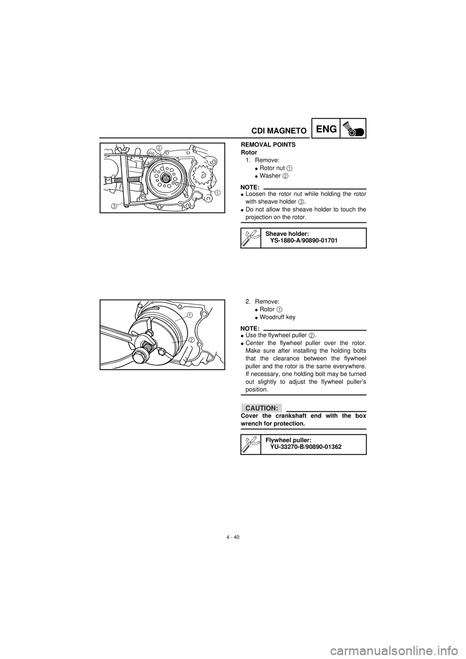
REMOVAL POINTS
Rotor
1. Remove:
lRotor nut 1
lWasher 2
NOTE:
lLoosen the rotor nut while holding the rotor
with sheave holder 3.
lDo not allow the sheave holder to touch the
projection on the rotor.
Sheave holder:
YS-1880-A/90890-01701
2. Remove:
lRotor 1
lWoodruff key
NOTE:
lUse the flywheel puller 2.
lCenter the flywheel puller over the rotor.
Make sure after installing the holding bolts
that the clearance between the flywheel
puller and the rotor is the same everywhere.
If necessary, one holding bolt may be turned
out slightly to adjust the flywheel puller’s
position.
CAUTION:
Cover the crankshaft end with the box
wrench for protection.
Flywheel puller:
YU-33270-B/90890-01362
Page 227 of 288
4 - 40
ENG
MAGNETO CDI
CDI-SCHWUNGRADMAGNETZÜNDER
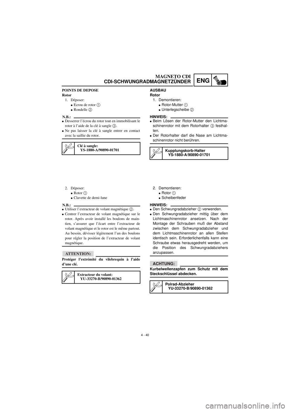
AUSBAU
Rotor
1. Demontieren:
lRotor-Mutter 1
lUnterlegscheibe 2
HINWEIS:
lBeim Lösen der Rotor-Mutter den Lichtma-
schinenrotor mit dem Rotorhalter 3 festhal-
ten.
lDer Rotorhalter darf die Nase am Lichtma-
schinenrotor nicht berühren.
Kupplungskorb-Halter
YS-1880-A/90890-01701
2. Demontieren:
lRotor 1
lScheibenfeder
HINWEIS:
lDen Schwungradabzieher 2 verwenden.
lDen Schwungradabzieher mittig über dem
Lichtmaschinenrotor ansetzen. Nach der
Montage der Schrauben muß der Abstand
zwischen dem Schwungradabzieher und
dem Lichtmaschinenrotor an allen Stellen
identisch sein. Erforderlichenfalls kann eine
Schraube etwas herausgedreht werden, um
die Position des Schwungradabziehers
anzupassen.
ACHTUNG:
Kurbelwellenzapfen zum Schutz mit dem
Steckschlüssel abdecken.
Polrad-Abzieher
YU-33270-B/90890-01362
POINTS DE DEPOSE
Rotor
1. Déposer:
lEcrou de rotor 1
lRondelle 2
N.B.:
lDesserrer l’écrou du rotor tout en immobilisant le
rotor à l’aide de la clé à sangle 3.
lNe pas laisser la clé à sangle entrer en contact
avec la saillie du rotor.
Clé à sangle:
YS-1880-A/90890-01701
2. Déposer:
lRotor 1
lClavette de demi-lune
N.B.:
lUtiliser l’extracteur de volant magnétique 2.
lCentrer l’extracteur de volant magnétique sur le
rotor. Après avoir installé les boulons de main-
tien, s’assurer que l’écart entre l’extracteur de
volant magnétique et le rotor est le même partout.
Au besoin, dévisser légèrement l’un des boulons
pour régler la position de l’extracteur de volant
magnétique.
ATTENTION:
Protéger l’extrémité du vilebrequin à l’aide
d’une clé.
Extracteur du volant:
YU-33270-B/90890-01362
Page 228 of 288
4 - 41
ENG
CRANKCASE AND CRANKSHAFT
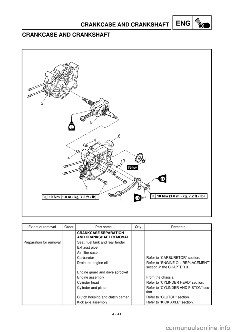
CRANKCASE AND CRANKSHAFT
Extent of removal Order Part name Q’ty Remarks
CRANKCASE SEPARATION
AND CRANKSHAFT REMOVAL
Preparation for removal Seat, fuel tank and rear fender
Exhaust pipe
Air filter case
Carburetor Refer to “CARBURETOR” section.
Drain the engine oil Refer to “ENGINE OIL REPLACEMENT”
section in the CHAPTER 3.
Engine guard and drive sprocket
Engine assembly From the chassis.
Cylinder head Refer to “CYLINDER HEAD” section.
Cylinder and piston Refer to “CYLINDER AND PISTON” sec-
tion.
Clutch housing and clutch carrier Refer to “CLUTCH” section.
Kick axle assembly Refer to “KICK AXLE” section.
Page 229 of 288

4 - 41
ENG
CARTER ET VILEBREQUIN
KURBELGEHÄUSE UND KURBELWELLE
KURBELGEHÄUSE UND KURBELWELLE
Demontage-ArbeitenReihen-
folgeBauteil Anz. Bemerkungen
KURBELGEHÄUSE TEILEN
UND KURBELWELLE DEMON-
TIEREN
Vorbereitung für den
AusbauSitz, Kraftstofftank und hinteres
Schutzblech
Krümmer
Luftfiltergehäuse
VergaserSiehe unter “VERGASER”.
Motoröl ablassen Siehe unter “MOTORÖL WECHSELN”
im KAPITEL 3.
Motorschutz und Antriebsritzel
Motor (vom Motor)
Zylinderkopf Siehe unter “ZYLINDERKOPF”.
Zylinder und Kolben Siehe unter “ZYLINDER UND KOLBEN”.
Kupplungsgehäuse und Kupp-
lungskorbSiehe unter “KUPPLUNG”.
Kickstarter Siehe unter “KICKSTARTERWELLE”.
CARTER ET VILEBREQUIN
Organisation de la dépose Ordre Nom de pièce Qté Remarques
SEPARATION DES DEMI-CAR-
TERS ET DEPOSE DU VILE-
BREQUIN
Préparation à la dépose Selle, réservoir de carburant et
garde-boue arrière
Tuyau d’échappment
Boîtier de filtre à air
Carburateur Se reporter à la section “CARBURATEUR”.
Vidanger l’huile moteur Se reporter à la section “REMPLACEMENT
DE L’HUILE MOTEUR” au CHAPITRE 3.
Protège-carter et pignon d’entraîne-
ment
Bloc moteur Du cadre
Culasse Se reporter à la section “CULASSE”.
Cylindre et piston Se reporter à la section “CYLINDRE ET
PISTON”.
Cloche d’embrayage et support
d’embrayageSe reporter à “EMBRAYAGE”.
Arbre de kick complet Se reporter à la section “ARBRE DE KICK”.
Page 230 of 288
4 - 42
ENG
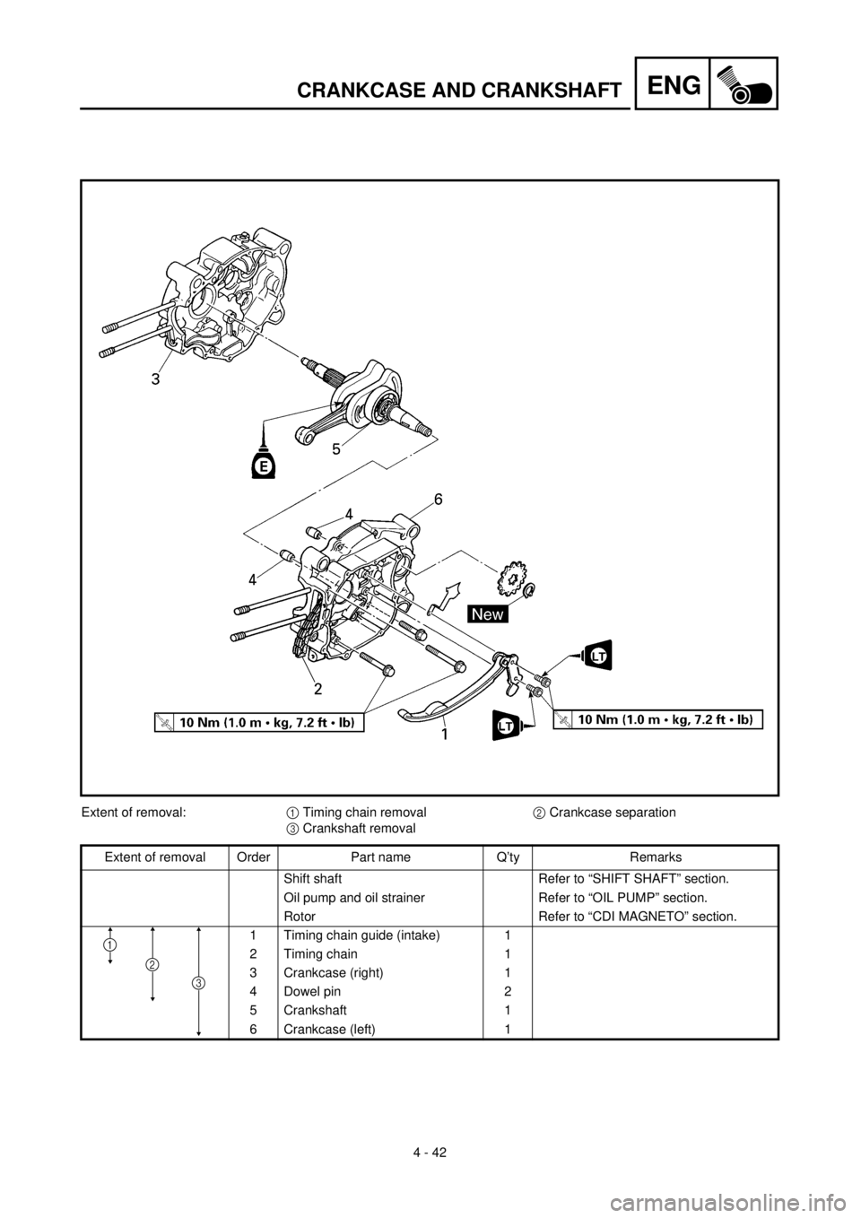
CRANKCASE AND CRANKSHAFT
Extent of removal:
1
Timing chain removal
2
Crankcase separation
3
Crankshaft removal
Extent of removal Order Part name Q’ty Remarks
Shift shaft Refer to “SHIFT SHAFT” section.
Oil pump and oil strainer Refer to “OIL PUMP” section.
Rotor Refer to “CDI MAGNETO” section.
1 Timing chain guide (intake) 1
2 Timing chain 1
3 Crankcase (right) 1
4 Dowel pin 2
5 Crankshaft 1
6 Crankcase (left) 1
1
2
3