service YAMAHA VX110 2005 Repair Manual
[x] Cancel search | Manufacturer: YAMAHA, Model Year: 2005, Model line: VX110, Model: YAMAHA VX110 2005Pages: 347, PDF Size: 14.17 MB
Page 142 of 347

5-43
EPOWRCAMSHAFTS
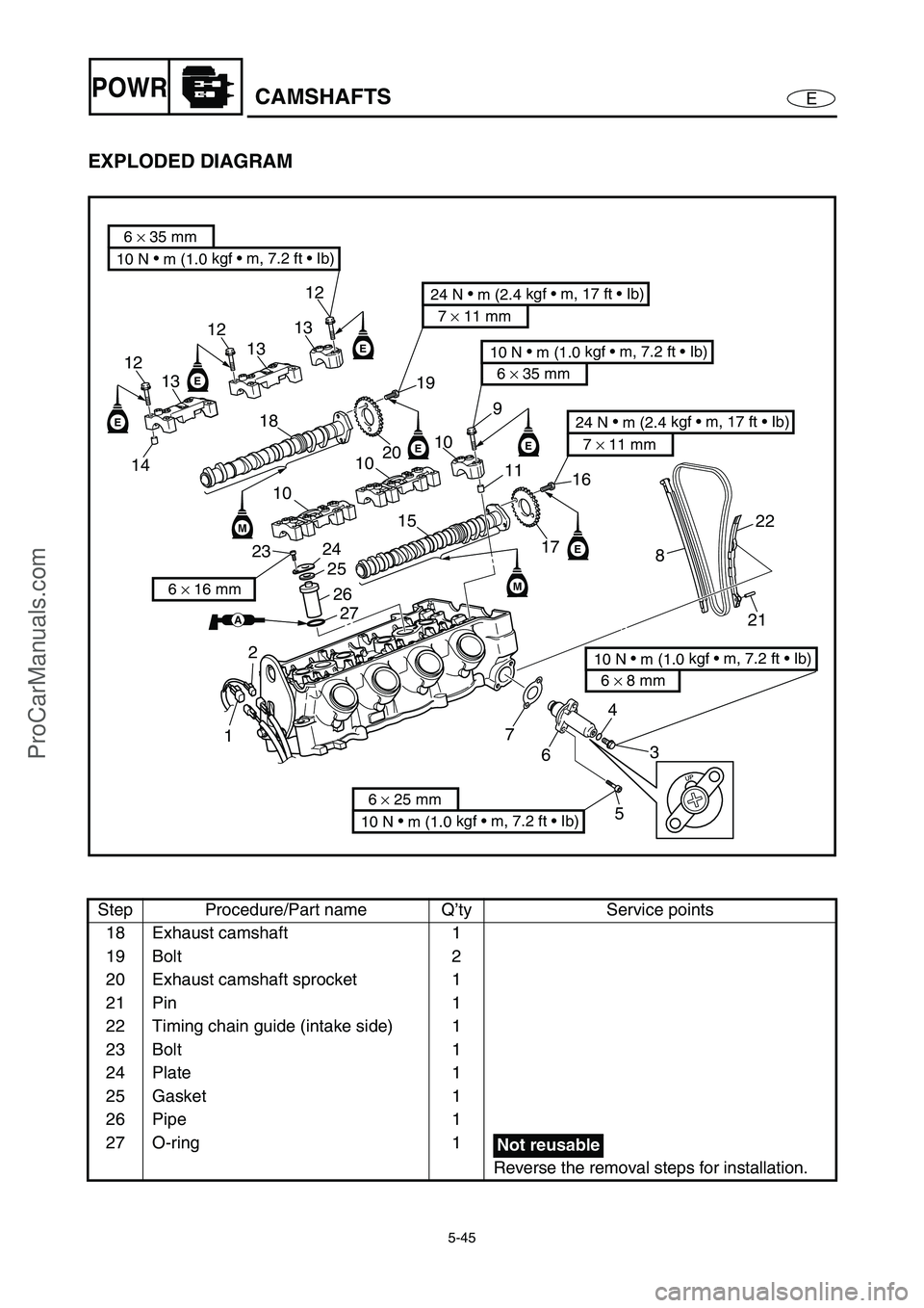
EXPLODED DIAGRAM
REMOVAL AND INSTALLATION CHART
Step Procedure/Part name Q’ty Service points
CAMSHAFT REMOVAL
Follow the left “Step” for removal.
Cylinder head cover
Reduction drive gear case Refer to “REDUCTION DRIVE GEAR”.
NOTE:
When removing camshafts it is not neces-
sary to remove the reduction drive gear
case.
1 Thermoswitch (engine) coupler 1
2 Engine temperature sensor coupler 1
3 Cap bolt 1
4Gasket 1
5Bolt 2
M
E
EE
E
E
E
M
12
13
12
13
12
13
141819
10
20
10
10
15
11
16
9
17
822
21
3 4
5 6 7
10 N
m (1.0 kgf m, 7.2 ft Ib)
6 × 35 mm
10 N
m (1.0 kgf m, 7.2 ft Ib)
6 × 35 mm
10 N
m (1.0 kgf m, 7.2 ft Ib)
6 × 25 mm
10 N
m (1.0 kgf m, 7.2 ft Ib)
6 × 8 mm
24 N
m (2.4 kgf m, 17 ft Ib)
7 × 11 mm
24 N
m (2.4 kgf m, 17 ft Ib)
7 × 11 mm
2324
25
26
27
12
6 × 16 mm
AA
Not reusable
ProCarManuals.com
Page 143 of 347

5-44
EPOWRCAMSHAFTS
EXPLODED DIAGRAM
Step Procedure/Part name Q’ty Service points
6 Timing chain tensioner 1
7 Timing chain tensioner gasket 1
8 Timing chain guide (exhaust side) 1
9Bolt 18
10 Intake camshaft cap 3
11 Dowel pin 6
12 Bolt 10
13 Exhaust camshaft cap 3
14 Dowel pin 6
15 Intake camshaft 1
16 Bolt 2
17 Intake camshaft sprocket 1
M
E
EE
E
E
E
M
12
13
12
13
12
13
141819
10
20
10
10
15
11
16
9
17
822
21
3 4
5 6 7
10 N •
m (1.0 kgf m, 7.2 ft Ib)
6 × 35 mm
10 N
m (1.0 kgf m, 7.2 ft Ib)
6 × 35 mm
10 N
m (1.0 kgf m, 7.2 ft Ib)
6 × 25 mm
10 N
m (1.0 kgf m, 7.2 ft Ib)
6 × 8 mm
24 N
m (2.4 kgf m, 17 ft Ib)
7 × 11 mm
24 N
m (2.4 kgf m, 17 ft Ib)
7 × 11 mm
2324
25
26
27
12
6 × 16 mm
AA
Not reusable
ProCarManuals.com
Page 144 of 347

5-45
EPOWRCAMSHAFTS
EXPLODED DIAGRAM
Step Procedure/Part name Q’ty Service points
18 Exhaust camshaft 1
19 Bolt 2
20 Exhaust camshaft sprocket 1
21 Pin 1
22 Timing chain guide (intake side) 1
23 Bolt 1
24 Plate 1
25 Gasket 1
26 Pipe 1
27 O-ring 1
Reverse the removal steps for installation.
M
E
EE
E
E
E
M
12
13
12
13
12
13
141819
10
20
10
10
15
11
16
9
17
822
21
3 4
5 6 7
10 N
m (1.0 kgf m, 7.2 ft Ib)
6 × 35 mm
10 N
m (1.0 kgf m, 7.2 ft Ib)
6 × 35 mm
10 N
m (1.0 kgf m, 7.2 ft Ib)
6 × 25 mm
10 N
m (1.0 kgf m, 7.2 ft Ib)
6 × 8 mm
24 N
m (2.4 kgf m, 17 ft Ib)
7 × 11 mm
24 N
m (2.4 kgf m, 17 ft Ib)
7 × 11 mm
2324
25
26
27
12
6 × 16 mm
AA
Not reusable
ProCarManuals.com
Page 145 of 347

5-46
EPOWRCAMSHAFTS
SERVICE POINTS
Camshaft removal
1. Install:
Dial gauge needle
Dial gauge stand 1
(into spark plug hole #1)
Dial gauge 2
2. Turn the drive coupling counterclockwise,
and then check if cylinder #1 is at TDC of
the compression stroke with a dial gauge.
NOTE:
TDC on the compression stroke can be found
when the camshaft lobes are turned away from
each other.
Dial gauge stand:
90890-06583
Dial gauge needle:
90890-06584
Dial gauge stand set:
YB-06585/90890-06585
Dial indicator gauge:
YU-03097
Dial gauge set:
90890-01252
2
1
INEX
3. Make the alignment marks a on the timing
chain and camshaft sprockets.
a
4. Remove:
Timing chain tensioner 1
Gasket
1
ProCarManuals.com
Page 146 of 347

5-47
EPOWRCAMSHAFTS
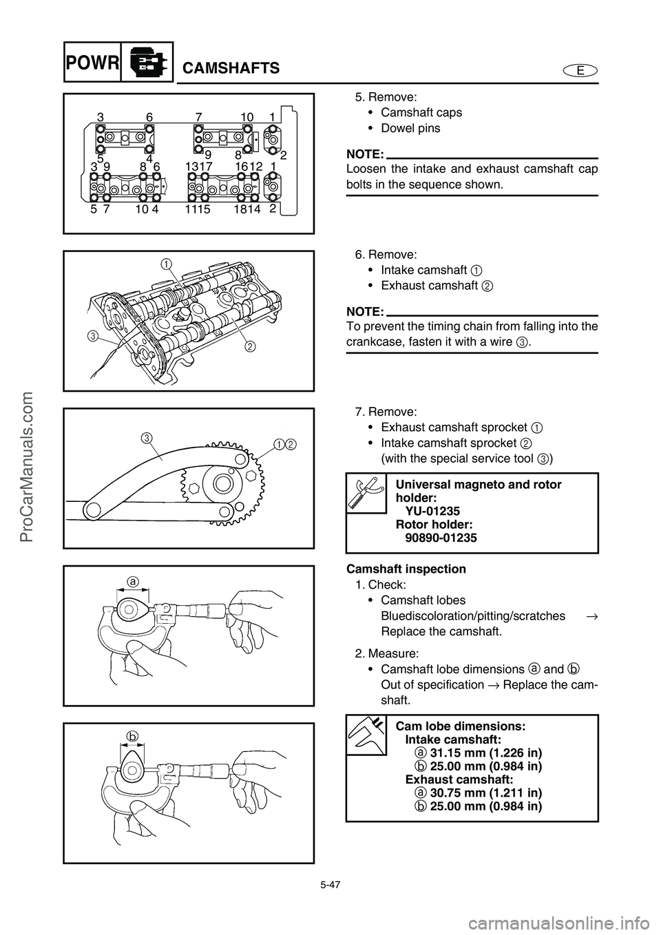
5. Remove:
Camshaft caps
Dowel pins
NOTE:
Loosen the intake and exhaust camshaft cap
bolts in the sequence shown.
1 10 7 6 3
2
14 18 15 11 4 10 7 52 8 9
4 5
1 12 16 17 13
6 8 9 3
6. Remove:
Intake camshaft 1
Exhaust camshaft 2
NOTE:
To prevent the timing chain from falling into the
crankcase, fasten it with a wire 3
.
7. Remove:
Exhaust camshaft sprocket 1
Intake camshaft sprocket 2
(with the special service tool 3
)
Universal magneto and rotor
holder:
YU-01235
Rotor holder:
90890-01235
Camshaft inspection
1. Check:
Camshaft lobes
Bluediscoloration/pitting/scratches →
Replace the camshaft.
2. Measure:
Camshaft lobe dimensions a
and b
Out of specification →
Replace the cam-
shaft.
Cam lobe dimensions:
Intake camshaft:
a 31.15 mm (1.226 in)
b 25.00 mm (0.984 in)
Exhaust camshaft:
a 30.75 mm (1.211 in)
b 25.00 mm (0.984 in)
ProCarManuals.com
Page 149 of 347

5-50
EPOWRCAMSHAFTS
Camshaft installation
1. Install:
Exhaust camshaft sprocket 1
Intake camshaft sprocket 2
(with the special service tool 3
)
NOTE:
Install the camshaft sprocket with the punch
mark a
facing outside.
Universal magneto and rotor
holder:
YU-01235
Rotor holder:
90890-01235
T R..
Camshaft sprocket bolt:
24 N m (2.4 kgf m, 17 ft lb)
2. Install:
Exhaust camshaft
Intake camshaft
Exhaust camshaft caps
Intake camshaft caps
Installation steps:
Turn the drive coupling counterclockwise,
and then check if cylinder #1 is at TDC of
the compression stroke with a dial gauge.
Install the timing chain onto both cam-
shaft sprockets, and then install the cam-
shaft.
CAUTION:
Do not turn the crankshaft when install-
ing the camshaft to avoid damage or
improper valve timing.
NOTE:
Make sure that the punch marks a
on the
camshafts face up.
Be sure to align the alignment marks b
made during removal to install the timing
chain and camshaft sprockets.
b
ProCarManuals.com
Page 153 of 347

5-54
EPOWRCYLINDER HEAD
CYLINDER HEAD
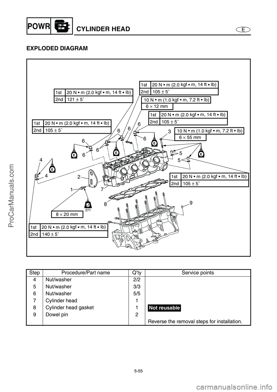
EXPLODED DIAGRAM
REMOVAL AND INSTALLATION CHART
Step Procedure/Part name Q’ty Service points
CYLINDER HEAD REMOVAL
Follow the left “Step” for removal.
Engine unit Refer to “ENGINE UNIT”.
Intake assembly Refer to “FUEL INJECTION SYSTEM” in
Chapter 4.
Exhaust pipes 1 and 2 Refer to “EXHAUST PIPES 1 AND 2”.
Oil tank Refer to “OIL TANK”.
Intake and exhaust camshaft Refer to “CAMSHAFTS”.
1Bolt 2
2 Hunger 1
3Bolt 3
EEE
E
2 4
1
855
7
9 3 6
6
LT
271
2nd 121 ± 5˚ 1st 20 N • m (2.0 kgf
• m, 14 ft
• Ib)
2nd 140 ± 5˚ 1st 20 N • m (2.0 kgf
• m, 14 ft
• Ib)
10 N •
m (1.0 kgf • m, 7.2 ft • Ib)
6 × 12 mm
10 N •
m (1.0 kgf • m, 7.2 ft • Ib)
6 × 55 mm
8 × 20 mm
6
2nd 105 ± 5˚ 1st 20 N • m (2.0 kgf
• m, 14 ft
• Ib)
2nd 105 ± 5˚ 1st 20 N • m (2.0 kgf
• m, 14 ft
• Ib)
2nd 105 ± 5˚ 1st 20 N • m (2.0 kgf
• m, 14 ft
• Ib)
2nd 105 ± 5˚ 1st 20 N • m (2.0 kgf
• m, 14 ft
• Ib)
E6
4
66
6
ProCarManuals.com
Page 154 of 347

5-55
EPOWRCYLINDER HEAD
EXPLODED DIAGRAM
Step Procedure/Part name Q’ty Service points
4 Nut/washer 2/2
5 Nut/washer 3/3
6 Nut/washer 5/5
7 Cylinder head 1
8 Cylinder head gasket 1
9 Dowel pin 2
Reverse the removal steps for installation.
EEE
E
2 4
1
855
7
9 3 6
6
LT
271
2nd 121 ± 5˚ 1st 20 N • m (2.0 kgf
• m, 14 ft
• Ib)
2nd 140 ± 5˚ 1st 20 N • m (2.0 kgf
• m, 14 ft
• Ib)
10 N •
m (1.0 kgf • m, 7.2 ft • Ib)
6 × 12 mm
10 N •
m (1.0 kgf • m, 7.2 ft • Ib)
6 × 55 mm
8 × 20 mm
6
2nd 105 ± 5˚ 1st 20 N • m (2.0 kgf
• m, 14 ft
• Ib)
2nd 105 ± 5˚ 1st 20 N • m (2.0 kgf
• m, 14 ft
• Ib)
2nd 105 ± 5˚ 1st 20 N • m (2.0 kgf
• m, 14 ft
• Ib)
2nd 105 ± 5˚ 1st 20 N • m (2.0 kgf
• m, 14 ft
• Ib)
E6
4
66
6
Not reusable
ProCarManuals.com
Page 155 of 347

5-56
EPOWRCYLINDER HEAD
SERVICE POINTS
Cylinder head removal
1. Remove:
Cylinder head bolts 1
2. Remove:
Cylinder head nuts
NOTE:
Loosen the cylinder head nuts in the sequence
shown.
Cylinder head inspection
1. Eliminate:
Combustion chamber carbon deposits
(with a rounded scraper)
NOTE:
Do not use a sharp instrument to avoid damag-
ing or scratching:
spark plug bore threads
valve seats
2. Check:
Cylinder head
Damage/scratches →
Replace.
Cylinder head water jacket
Mineral deposits/rust →
Eliminate.
ProCarManuals.com
Page 158 of 347

5-59
EPOWRVALVES AND VALVE SPRINGS
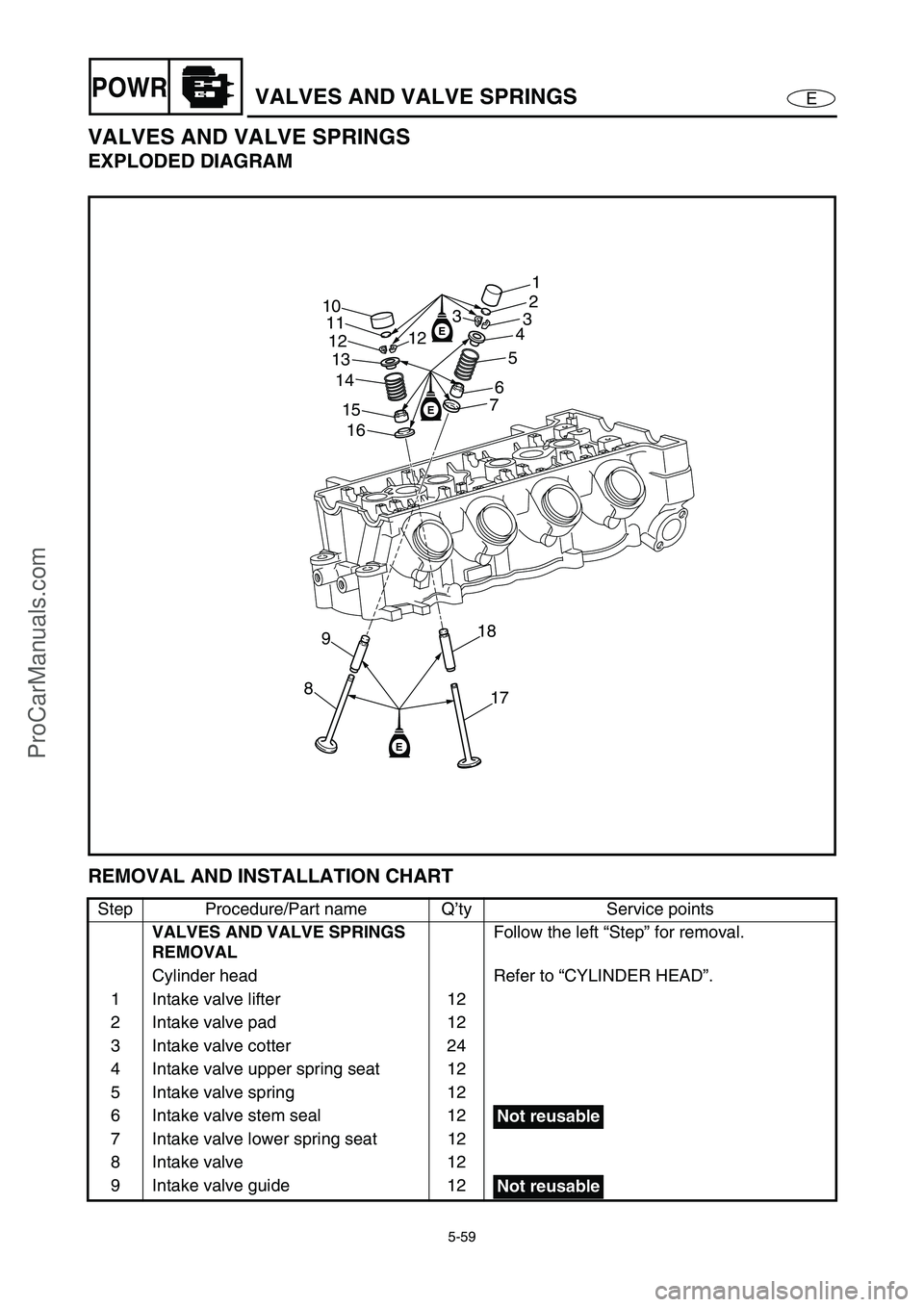
VALVES AND VALVE SPRINGS
EXPLODED DIAGRAM
REMOVAL AND INSTALLATION CHART
Step Procedure/Part name Q’ty Service points
VALVES AND VALVE SPRINGS
REMOVALFollow the left “Step” for removal.
Cylinder head Refer to “CYLINDER HEAD”.
1 Intake valve lifter 12
2 Intake valve pad 12
3 Intake valve cotter 24
4 Intake valve upper spring seat 12
5 Intake valve spring 12
6 Intake valve stem seal 12
7 Intake valve lower spring seat 12
8 Intake valve 12
9 Intake valve guide 12
E
E
E
89
17 18 16 15 14 13 10
11
121
2
3
4
5
6
7 3
12
Not reusable
Not reusable
ProCarManuals.com