service YAMAHA VX110 2005 Manual PDF
[x] Cancel search | Manufacturer: YAMAHA, Model Year: 2005, Model line: VX110, Model: YAMAHA VX110 2005Pages: 347, PDF Size: 14.17 MB
Page 159 of 347
5-60
EPOWRVALVES AND VALVE SPRINGS
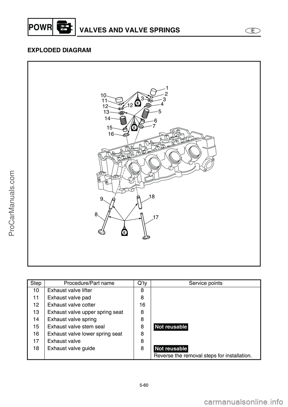
EXPLODED DIAGRAM
Step Procedure/Part name Q’ty Service points
10 Exhaust valve lifter 8
11 Exhaust valve pad 8
12 Exhaust valve cotter 16
13 Exhaust valve upper spring seat 8
14 Exhaust valve spring 8
15 Exhaust valve stem seal 8
16 Exhaust valve lower spring seat 8
17 Exhaust valve 8
18 Exhaust valve guide 8
Reverse the removal steps for installation.
E
E
E
89
17 18 16 15 14 13 10
11
121
2
3
4
5
6
7 3
12
Not reusable
Not reusable
ProCarManuals.com
Page 160 of 347
5-61
EPOWRVALVES AND VALVE SPRINGS
SERVICE POINTS
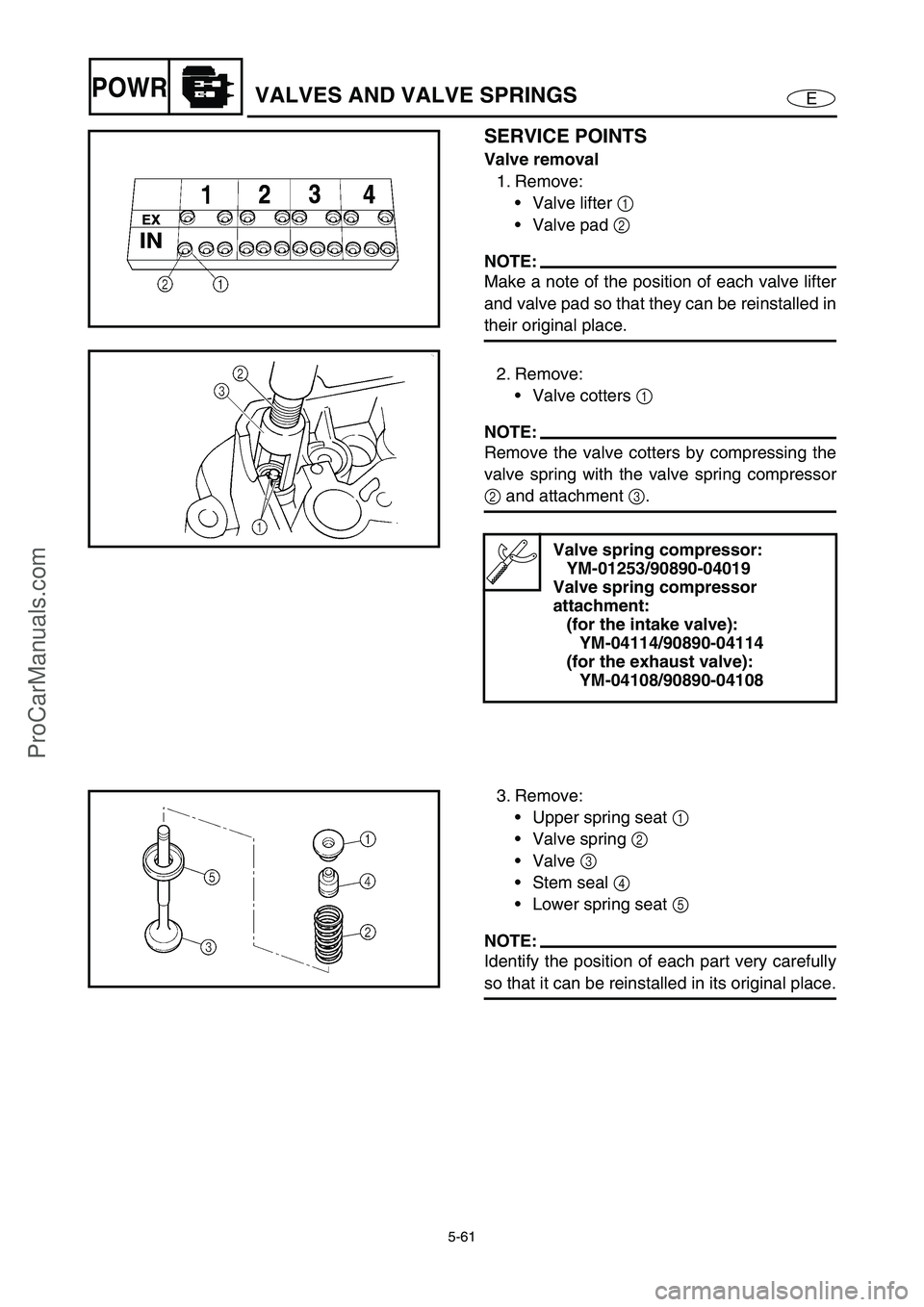
Valve removal
1. Remove:
Valve lifter 1
Valve pad 2
NOTE:
Make a note of the position of each valve lifter
and valve pad so that they can be reinstalled in
their original place.
2. Remove:
Valve cotters 1
NOTE:
Remove the valve cotters by compressing the
valve spring with the valve spring compressor
2
and attachment 3
.
Valve spring compressor:
YM-01253/90890-04019
Valve spring compressor
attachment:
(for the intake valve):
YM-04114/90890-04114
(for the exhaust valve):
YM-04108/90890-04108
3. Remove:
Upper spring seat 1
Valve spring 2
Valve 3
Stem seal 4
Lower spring seat 5
NOTE:
Identify the position of each part very carefully
so that it can be reinstalled in its original place.
ProCarManuals.com
Page 163 of 347
5-64
EPOWRVALVES AND VALVE SPRINGS
Valve guide inspection
NOTE:
Before checking the valve guide make sure
that the valve stem diameter is within specifi-
cation.
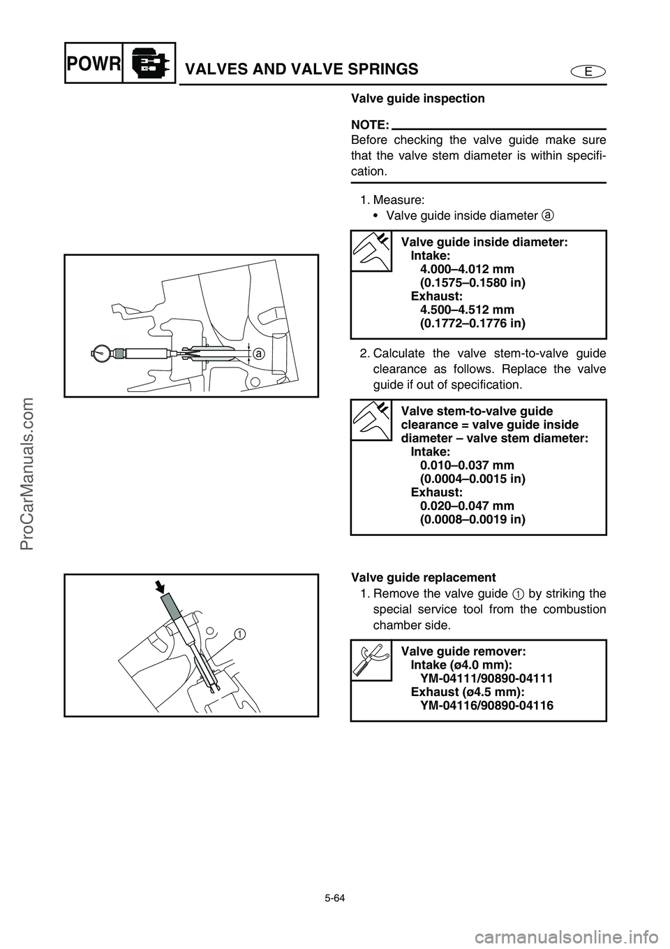
1. Measure:
Valve guide inside diameter a
2. Calculate the valve stem-to-valve guide
clearance as follows. Replace the valve
guide if out of specification.
Valve guide inside diameter:
Intake:
4.000–4.012 mm
(0.1575–0.1580 in)
Exhaust:
4.500–4.512 mm
(0.1772–0.1776 in)
Valve stem-to-valve guide
clearance = valve guide inside
diameter – valve stem diameter:
Intake:
0.010–0.037 mm
(0.0004–0.0015 in)
Exhaust:
0.020–0.047 mm
(0.0008–0.0019 in)
a
Valve guide replacement
1. Remove the valve guide 1
by striking the
special service tool from the combustion
chamber side.
Valve guide remover:
Intake (ø4.0 mm):
YM-04111/90890-04111
Exhaust (ø4.5 mm):
YM-04116/90890-04116
1
ProCarManuals.com
Page 164 of 347

5-65
EPOWRVALVES AND VALVE SPRINGS
2. Install the new valve guide 2
by striking
the special service tool from the camshaft
side until the valve guide clip 3
contacts
the cylinder head.
NOTE:
Apply engine oil to the surface of the new
valve guide.
Valve guide remover:
Intake (ø4.0 mm):
YM-04111/90890-04111
Exhaust (ø4.5 mm):
YM-04116/90890-04116
Valve guide installer:
Intake (ø4.0 mm):
YM-04112/90890-04112
Exhaust (ø4.5 mm):
YM-04117/90890-04117
3
E
2
3. Insert the special service tool into the
valve guide 2
, and then ream the valve
guide.
NOTE:
Turn the valve guide reamer clockwise to
ream the valve guide.
Do not turn the reamer counterclockwise
when removing the reamer.
4. Measure:
Valve guide inside diameter
Valve guide reamer:
Intake (ø4.0 mm):
YM-04113/90890-04113
Exhaust (ø4.5 mm):
YM-04118/90890-04118
Valve guide inside diameter:
Intake:
4.000–4.012 mm
(0.1575–0.1580 in)
Exhaust:
4.500–4.512 mm
(0.1772–0.1776 in)
2
ProCarManuals.com
Page 170 of 347

5-71
EPOWRCRANKCASE
CRANKCASE
EXPLODED DIAGRAM
REMOVAL AND INSTALLATION CHART
Step Procedure/Part name Q’ty Service points
OIL PAN AND CRANKCASE
REMOVALFollow the left “Step” for removal.
Engine unit Refer to “ENGINE UNIT”.
Intake assembly Refer to “FUEL INJECTION SYSTEM” in
Chapter 4.
Exhaust pipes 1 and 2 Refer to “EXHAUST PIPES 1 AND 2”.
Exhaust manifold Refer to “EXHAUST MANIFOLD”.
Generator cover Refer to “GENERATOR AND STARTER
MOTOR”.
Oil tank Refer to “OIL TANK”.
Oil pump Refer to “OIL PUMP”.
*: Loosen completely
6
21 20
20 11
10 9
87
23
4
5
16
151718
13 14
1219
1
LT
271
LT
LT
572
LT
LT
572
LT
LT
572
LT
LT
572
LT
LT
572
LT
E
E
AA
12 N •
m (1.2 kgf • m, 8.7 ft • Ib)
6 × 70 mm
12 N •
m (1.2 kgf • m, 8.7 ft • Ib)
6 × 20 mm
20 N •
m (2.0 kgf • m, 14 ft • Ib)
8 × 40 mm
2nd *
3rd 15 N • m (1.5 kgf
• m, 11 ft
• Ib) 1st 7.8 N • m (0.78 kgf
• m, 5.6 ft
• Ib)
9 × 105 mm
4th 49 ± 5˚
8.4 N •
m (0.84 kgf • m, 6.1 ft • Ib)
12 N •
m (1.2 kgf • m, 8.7 ft • Ib)
6 × 55 mm
12 N •
m (1.2 kgf • m, 8.7 ft • Ib)
6 × 55 mm
7.6 N •
m (0.76 kgf • m, 5.5 ft • Ib)
6 × 16 mm
15 N •
m (1.5 kgf • m, 11 ft • Ib)
12 N •
m (1.2 kgf • m, 8.7 ft • Ib)
6 × 20 mm
18
AA
1280B
ProCarManuals.com
Page 171 of 347

5-72
EPOWRCRANKCASE
EXPLODED DIAGRAM
Step Procedure/Part name Q’ty Service points
Reduction drive gear case Refer to “REDUCTION DRIVE GEAR”.
Cylinder head Refer to “CAMSHAFTS”.
1 Timing chain 1
2 Engine temperature sensor 1
3 Washer 1
4Bolt 2
5 Thermoswitch (engine) 1
6 Oil pressure switch 1
7Bolt 1
8Bolt 1
9 Anode cover 1
10 Grommet 1
6
21 20
20 11
10 9
87
23
4
5
16
151718
13 14
1219
1
LT
271
LT
LT
572
LT
LT
572
LT
LT
572
LT
LT
572
LT
LT
572
LT
E
E
AA
12 N •
m (1.2 kgf • m, 8.7 ft • Ib)
6 × 70 mm
12 N •
m (1.2 kgf • m, 8.7 ft • Ib)
6 × 20 mm
20 N •
m (2.0 kgf • m, 14 ft • Ib)
8 × 40 mm
2nd *
3rd 15 N • m (1.5 kgf
• m, 11 ft
• Ib) 1st 7.8 N • m (0.78 kgf
• m, 5.6 ft
• Ib)
9 × 105 mm
4th 49 ± 5˚
8.4 N •
m (0.84 kgf • m, 6.1 ft • Ib)
12 N •
m (1.2 kgf • m, 8.7 ft • Ib)
6 × 55 mm
12 N •
m (1.2 kgf • m, 8.7 ft • Ib)
6 × 55 mm
7.6 N •
m (0.76 kgf • m, 5.5 ft • Ib)
6 × 16 mm
15 N •
m (1.5 kgf • m, 11 ft • Ib)
12 N •
m (1.2 kgf • m, 8.7 ft • Ib)
6 × 20 mm
18
AA
1280B
ProCarManuals.com
Page 172 of 347
5-73
EPOWRCRANKCASE
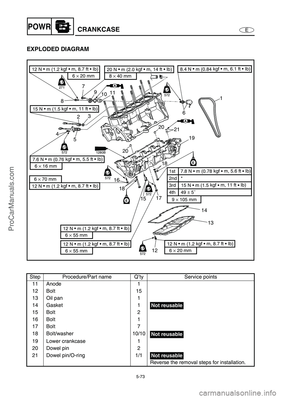
EXPLODED DIAGRAM
Step Procedure/Part name Q’ty Service points
11 Anode 1
12 Bolt 15
13 Oil pan 1
14 Gasket 1
15 Bolt 2
16 Bolt 1
17 Bolt 7
18 Bolt/washer 10/10
19 Lower crankcase 1
20 Dowel pin 2
21 Dowel pin/O-ring 1/1
Reverse the removal steps for installation.
6
21 20
20 11
10 9
87
23
4
5
16
151718
13 14
1219
1
LT
271
LT
LT
572
LT
LT
572
LT
LT
572
LT
LT
572
LT
LT
572
LT
E
E
AA
12 N •
m (1.2 kgf • m, 8.7 ft • Ib)
6 × 70 mm
12 N •
m (1.2 kgf • m, 8.7 ft • Ib)
6 × 20 mm
20 N •
m (2.0 kgf • m, 14 ft • Ib)
8 × 40 mm
2nd *
3rd 15 N • m (1.5 kgf
• m, 11 ft
• Ib) 1st 7.8 N • m (0.78 kgf
• m, 5.6 ft
• Ib)
9 × 105 mm
4th 49 ± 5˚
8.4 N •
m (0.84 kgf • m, 6.1 ft • Ib)
12 N •
m (1.2 kgf • m, 8.7 ft • Ib)
6 × 55 mm
12 N •
m (1.2 kgf • m, 8.7 ft • Ib)
6 × 55 mm
7.6 N •
m (0.76 kgf • m, 5.5 ft • Ib)
6 × 16 mm
15 N •
m (1.5 kgf • m, 11 ft • Ib)
12 N •
m (1.2 kgf • m, 8.7 ft • Ib)
6 × 20 mm
18
AA
1280B
Not reusable
Not reusable
Not reusable
ProCarManuals.com
Page 173 of 347
5-74
EPOWRCRANKCASE
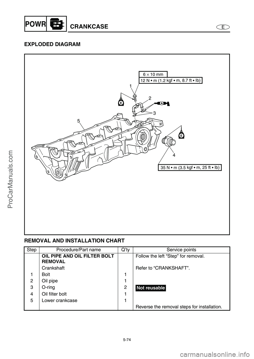
EXPLODED DIAGRAM
REMOVAL AND INSTALLATION CHART
Step Procedure/Part name Q’ty Service points
OIL PIPE AND OIL FILTER BOLT
REMOVALFollow the left “Step” for removal.
Crankshaft Refer to “CRANKSHAFT”.
1Bolt 1
2 Oil pipe 1
3 O-ring 2
4 Oil filter bolt 1
5 Lower crankcase 1
Reverse the removal steps for installation.
E
E
51
2
3
4
AA
6 × 10 mm
12 N • m (1.2 kgf
• m, 8.7 ft
• Ib)
35 N • m (3.5 kgf
• m, 25 ft
• Ib)
Not reusable
ProCarManuals.com
Page 174 of 347

5-75
EPOWRCRANKCASE
SERVICE POINTS
Crankcase disassembly
1. Remove:
Oil pan bolts
NOTE:
Loosen each bolt 1/4 of a turn at a time, in
stages and in a crisscross pattern. After all of
the bolts are fully loosened, remove them.
Loosen the bolts in decreasing numerical
order (refer to the numbers in the illustra-
tion).
The numbers embossed on the oil pan indi-
cate the oil pan tightening sequence.
106
24812
15
11
7
3 1 5 9
13 14
2. Remove:
Crankcase bolts
NOTE:
Loosen each bolt 1/4 of a turn at a time, in
stages and in a crisscross pattern. After all of
the bolts are fully loosened, remove them.
Loosen the bolts in decreasing numerical
order (refer to the numbers in the illustra-
tion).
The numbers embossed on the crankcase
indicate the crankcase tightening sequence.
3. Remove:
Lower crankcase
CAUTION:
Tap on one side of the crankcase with a
soft-face hammer. Tap only on reinforced
portions of the crankcase, not on the
crankcase mating surfaces. Work slowly
and carefully and make sure the crankcase
halves separate evenly.
M9
× 105 mm bolts:
1–
0
M6
× 55 mm bolts:
A–
H,
J
M6
× 70 mm bolts:
I
15397
ICAEG
86240
HFBDJ
ProCarManuals.com
Page 179 of 347
5-80
EPOWRCONNECTING RODS AND PISTONS
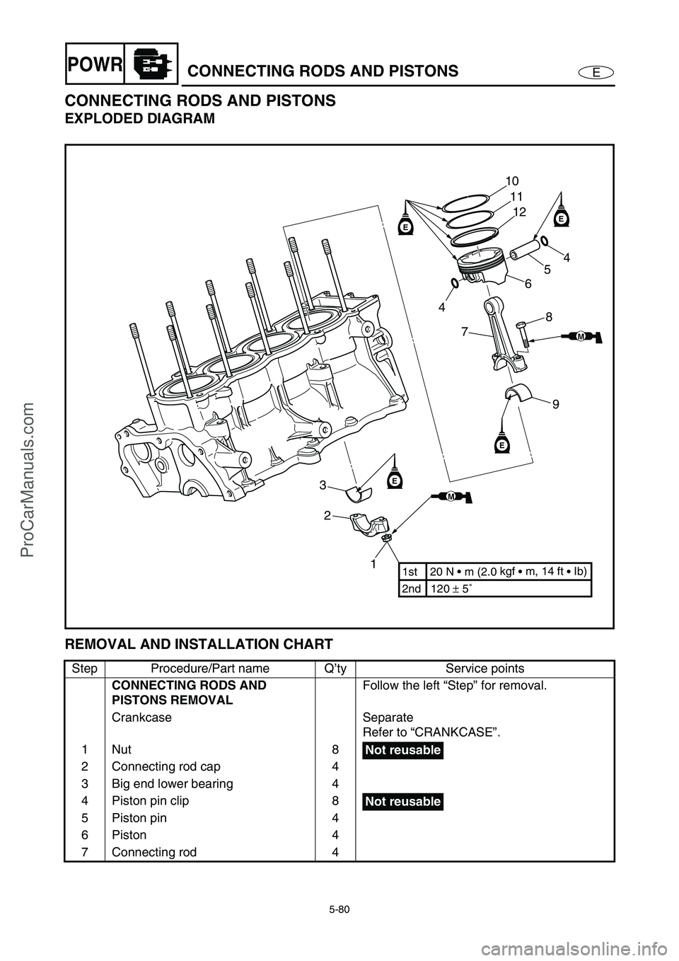
CONNECTING RODS AND PISTONS
EXPLODED DIAGRAM
REMOVAL AND INSTALLATION CHART
Step Procedure/Part name Q’ty Service points
CONNECTING RODS AND
PISTONS REMOVALFollow the left “Step” for removal.
Crankcase Separate
Refer to “CRANKCASE”.
1Nut 8
2 Connecting rod cap 4
3 Big end lower bearing 4
4 Piston pin clip 8
5 Piston pin 4
6Piston 4
7 Connecting rod 4
EE
E
E
1 2 310
11
12
4
5
6
8
7
9
2nd 120 ± 5˚ 1st 20 N • m (2.0 kgf
• m, 14 ft
• Ib)
MM
MM
4
Not reusable
Not reusable
ProCarManuals.com