service YAMAHA VX110 2005 Manual Online
[x] Cancel search | Manufacturer: YAMAHA, Model Year: 2005, Model line: VX110, Model: YAMAHA VX110 2005Pages: 347, PDF Size: 14.17 MB
Page 180 of 347
5-81
EPOWRCONNECTING RODS AND PISTONS
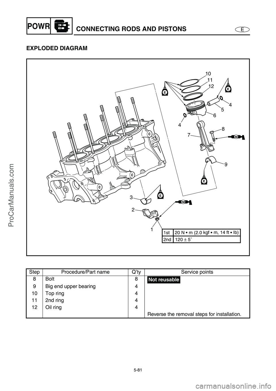
EXPLODED DIAGRAM
Step Procedure/Part name Q’ty Service points
8Bolt 8
9 Big end upper bearing 4
10 Top ring 4
11 2nd ring 4
12 Oil ring 4
Reverse the removal steps for installation.
EE
E
E
1 2 310
11
12
4
5
6
8
7
9
2nd 120 ± 5˚ 1st 20 N • m (2.0 kgf
• m, 14 ft
• Ib)
MM
MM
4
Not reusable
ProCarManuals.com
Page 181 of 347

5-82
EPOWRCONNECTING RODS AND PISTONS
SERVICE POINTS
Connecting rod and piston removal
The following procedure applies to all of the
connecting rods and pistons.
1. Remove:
Connecting rod cap 1
Big end bearings
NOTE:
Identify the position of each big end bearing so
that it can be reinstalled in its original place.
1
2. Remove:
Piston pin clips 1
Piston pin 2
Piston 3
Connecting rod 4
CAUTION:
Do not use a hammer to drive the piston
pin out.
NOTE:
For reference during installation, put an iden-
tification number a on the piston crown.
Before removing the piston pin, deburr the
piston pin clip’s groove and the piston’s pin
bore area.
3. Remove:
Top ring
2nd ring
Oil ring
NOTE:
When removing a piston ring, open the end
gap with your fingers and lift the other side of
the ring over the piston crown.
ProCarManuals.com
Page 192 of 347
5-93
EPOWRCRANKSHAFT
CRANKSHAFT
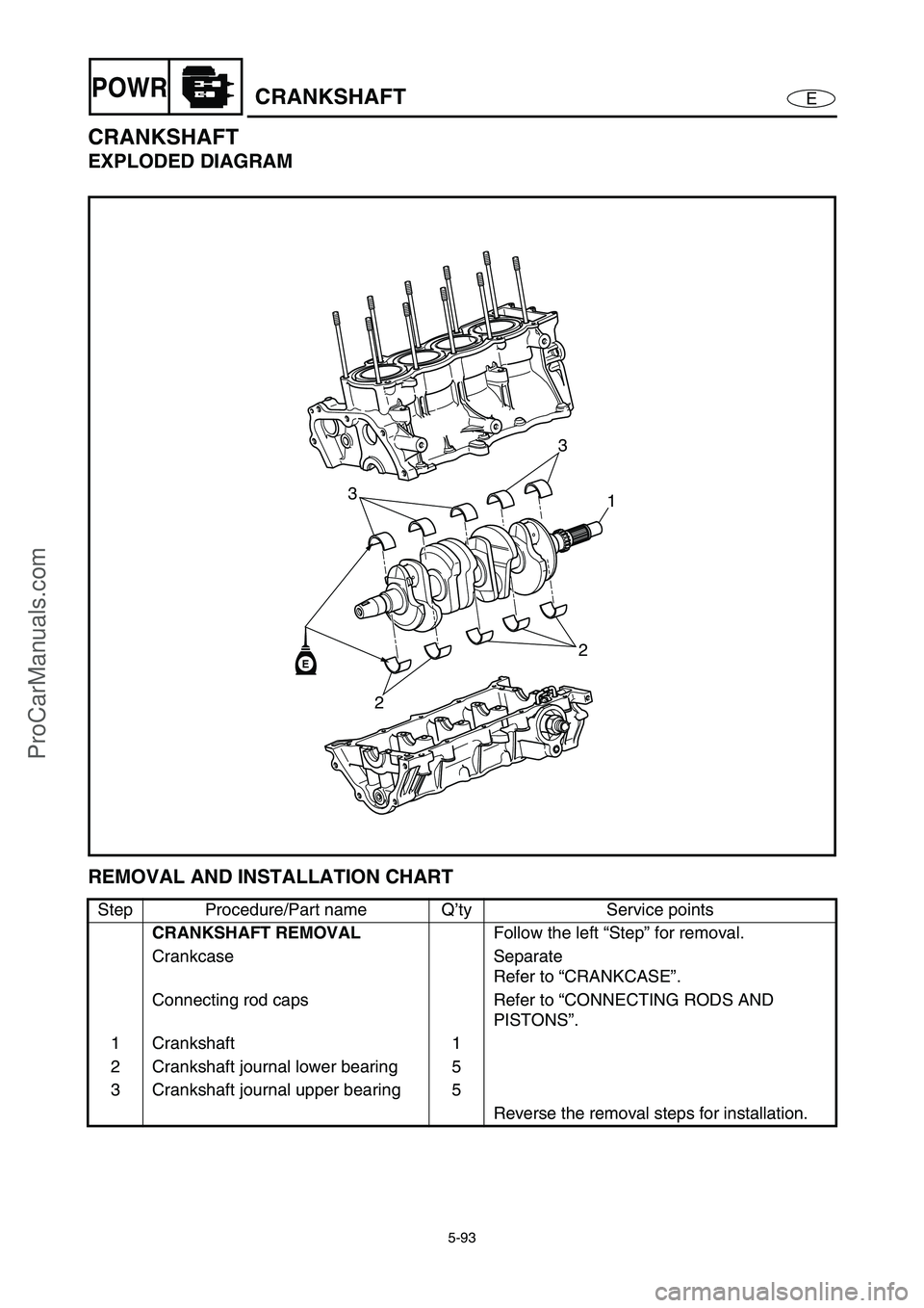
EXPLODED DIAGRAM
REMOVAL AND INSTALLATION CHART
Step Procedure/Part name Q’ty Service points
CRANKSHAFT REMOVAL
Follow the left “Step” for removal.
Crankcase Separate
Refer to “CRANKCASE”.
Connecting rod caps Refer to “CONNECTING RODS AND
PISTONS”.
1 Crankshaft 1
2 Crankshaft journal lower bearing 5
3 Crankshaft journal upper bearing 5
Reverse the removal steps for installation.
2
21 33E
ProCarManuals.com
Page 193 of 347
5-94
EPOWRCRANKSHAFT
SERVICE POINTS
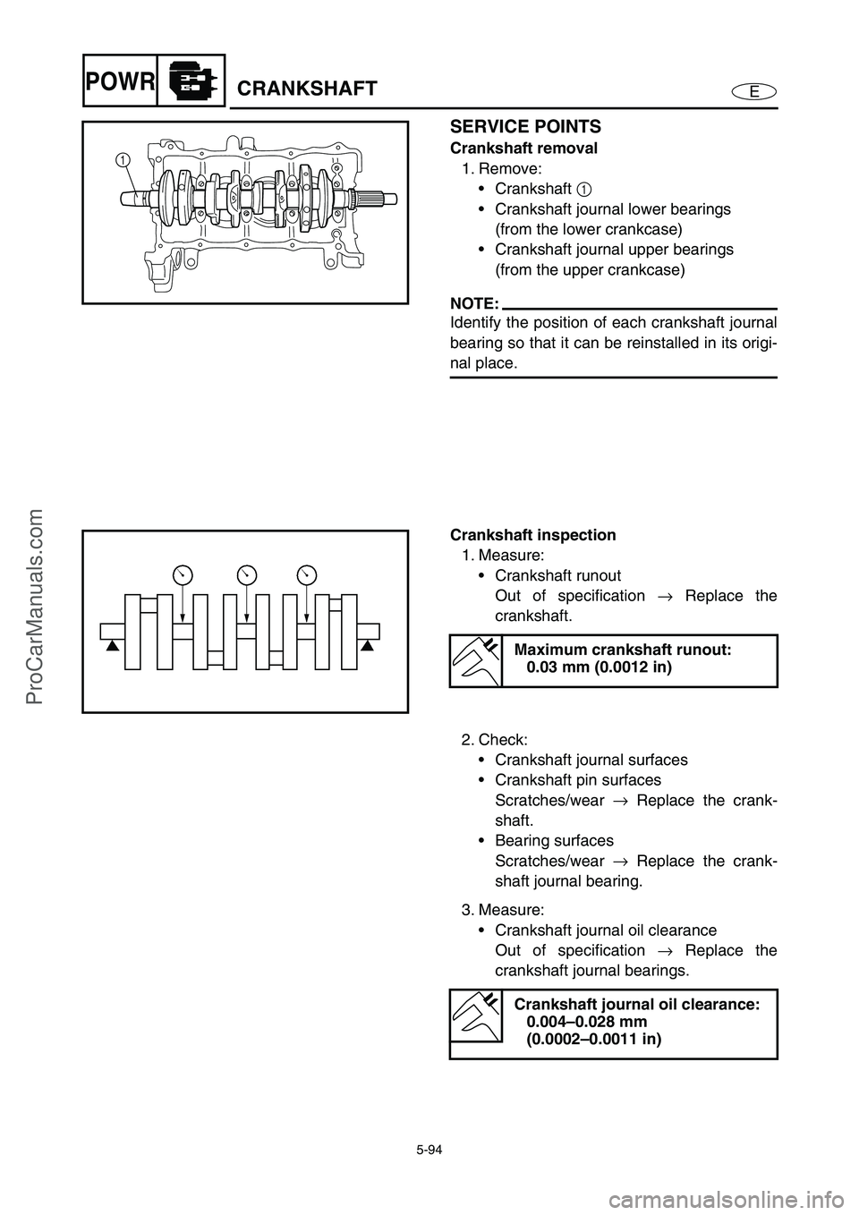
Crankshaft removal
1. Remove:
Crankshaft 1
Crankshaft journal lower bearings
(from the lower crankcase)
Crankshaft journal upper bearings
(from the upper crankcase)
NOTE:
Identify the position of each crankshaft journal
bearing so that it can be reinstalled in its origi-
nal place.
1
Crankshaft inspection
1. Measure:
Crankshaft runout
Out of specification →
Replace the
crankshaft.
Maximum crankshaft runout:
0.03 mm (0.0012 in)
2. Check:
Crankshaft journal surfaces
Crankshaft pin surfaces
Scratches/wear →
Replace the crank-
shaft.
Bearing surfaces
Scratches/wear →
Replace the crank-
shaft journal bearing.
3. Measure:
Crankshaft journal oil clearance
Out of specification →
Replace the
crankshaft journal bearings.
Crankshaft journal oil clearance:
0.004–0.028 mm
(0.0002–0.0011 in)
ProCarManuals.com
Page 197 of 347
5-98
EPOWRCOOLING WATER HOSE
COOLING WATER HOSE
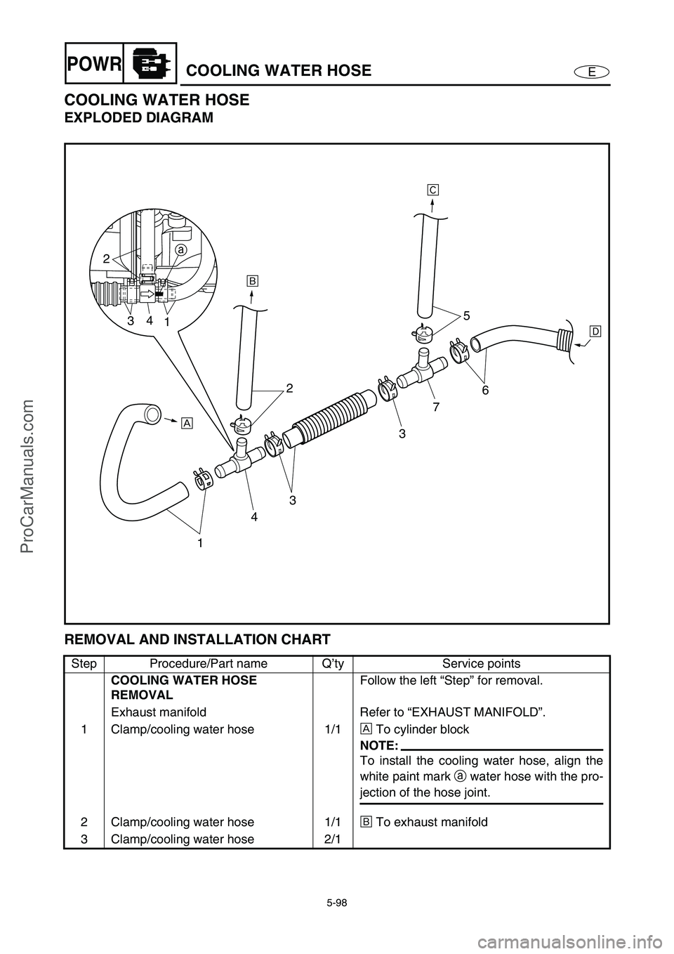
EXPLODED DIAGRAM
REMOVAL AND INSTALLATION CHART
Step Procedure/Part name Q’ty Service points
COOLING WATER HOSE
REMOVALFollow the left “Step” for removal.
Exhaust manifold Refer to “EXHAUST MANIFOLD”.
1 Clamp/cooling water hose 1/1È
To cylinder block
NOTE:
To install the cooling water hose, align the
white paint mark a
water hose with the pro-
jection of the hose joint.
2 Clamp/cooling water hose 1/1É
To exhaust manifold
3 Clamp/cooling water hose 2/1
143 2
375
6
ÈÉÊ
Ë
a
2
34
1
ProCarManuals.com
Page 198 of 347
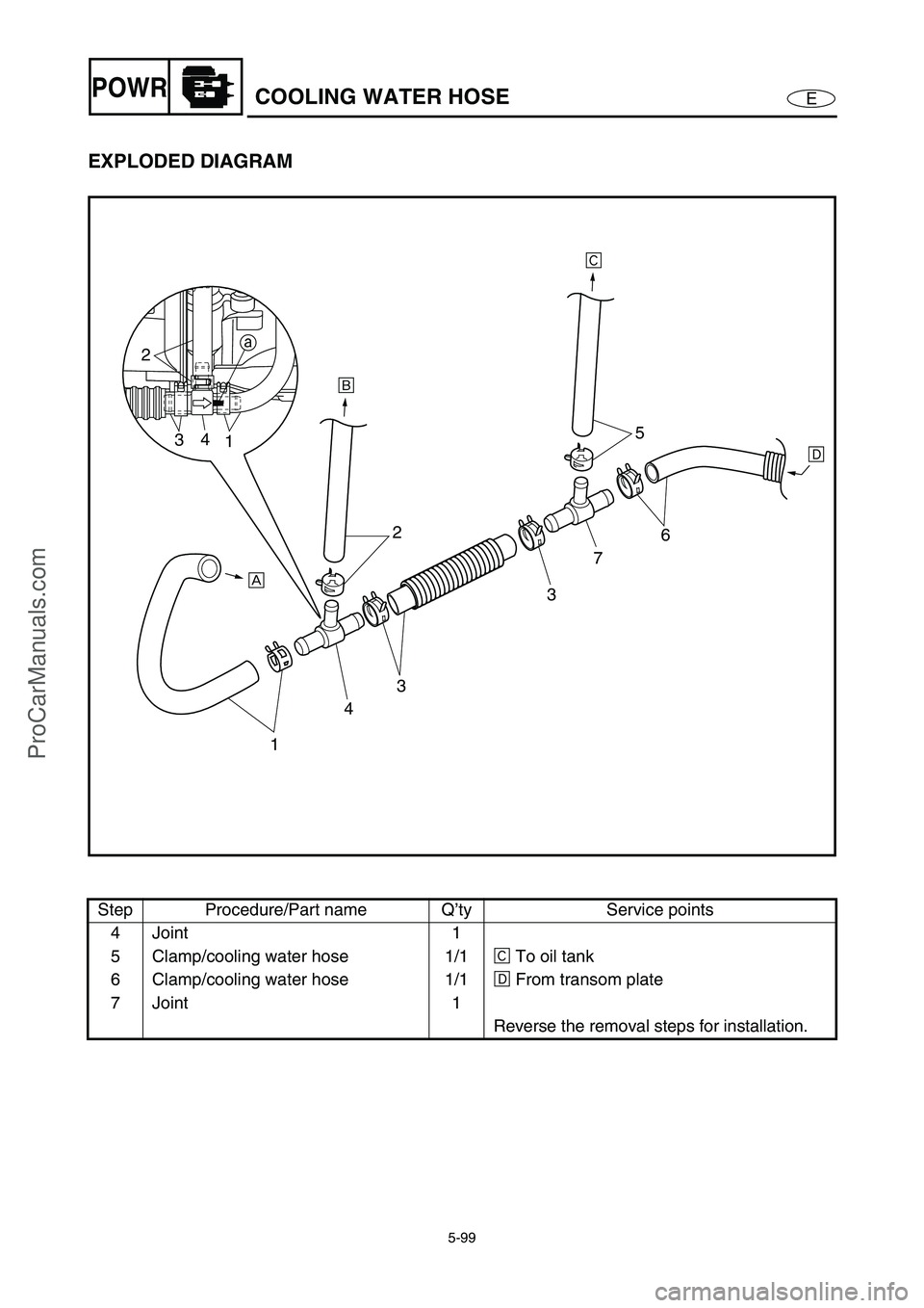
5-99
EPOWRCOOLING WATER HOSE
EXPLODED DIAGRAM
Step Procedure/Part name Q’ty Service points
4 Joint 1
5 Clamp/cooling water hose 1/1Ê
To oil tank
6 Clamp/cooling water hose 1/1Ë
From transom plate
7 Joint 1
Reverse the removal steps for installation.
143 2
375
6
ÈÉÊ
Ë
a
2
34
1
ProCarManuals.com
Page 199 of 347
E
JET
PUMP
1
2
3
4
5
6
7
8
9
CHAPTER 6
JET PUMP UNIT
INTAKE GRATE AND RIDE PLATE ............................................................... 6-1
EXPLODED DIAGRAM ............................................................................. 6-1
REMOVAL AND INSTALLATION CHART ................................................ 6-1
JET PUMP UNIT .............................................................................................. 6-3
EXPLODED DIAGRAM ............................................................................. 6-3
REMOVAL AND INSTALLATION CHART ................................................ 6-3
REVERSE GATE (DELUXE MODEL ONLY) .................................................. 6-5
EXPLODED DIAGRAM ............................................................................. 6-5
REMOVAL AND INSTALLATION CHART ................................................ 6-5
JET THRUST NOZZLE, IMPELLER DUCT, AND
IMPELLER HOUSING 1 ................................................................................. 6-6
EXPLODED DIAGRAM ............................................................................. 6-6
REMOVAL AND INSTALLATION CHART ................................................ 6-6
IMPELLER DUCT AND DRIVE SHAFT .......................................................... 6-8
EXPLODED DIAGRAM ............................................................................. 6-8
REMOVAL AND INSTALLATION CHART ................................................ 6-8
SERVICE POINTS .................................................................................. 6-10
Drive shaft removal ........................................................................... 6-10
Impeller inspection ............................................................................ 6-11
Drive shaft inspection ........................................................................ 6-11
Drive shaft installation ....................................................................... 6-12
TRANSOM PLATE AND HOSES .................................................................. 6-15
EXPLODED DIAGRAM ........................................................................... 6-15
REMOVAL AND INSTALLATION CHART .............................................. 6-15
SERVICE POINTS .................................................................................. 6-17
Bilge strainer inspection .................................................................... 6-17
Bilge hose inspection ........................................................................ 6-17
Cooling water hose inspection .......................................................... 6-17
BEARING HOUSING ..................................................................................... 6-18
EXPLODED DIAGRAM ........................................................................... 6-18
REMOVAL AND INSTALLATION CHART .............................................. 6-18
SERVICE POINTS .................................................................................. 6-21
Driven coupling removal and installation........................................... 6-21
Intermediate drive shaft removal ....................................................... 6-21
Bearing removal ................................................................................ 6-22
Bearing and intermediate drive shaft inspection ............................... 6-22
Driven coupling inspection ................................................................ 6-22
Bearing and oil seals installation ....................................................... 6-23
Intermediate drive shaft installation................................................... 6-24
ProCarManuals.com
Page 200 of 347

6-1
E
JET
PUMP
INTAKE GRATE AND RIDE PLATE
EXPLODED DIAGRAM
REMOVAL AND INSTALLATION CHART
Step Procedure/Part name Q’ty Service points
INTAKE GRATE, RIDE PLATE,
AND INTAKE DUCT REMOVALFollow the left “Step” for removal.
1Bolt 2
2Bolt 2
3 Intake grate 1
4Screw 4
5 Speed sensor 1
NOTE:
Route the speed sensor lead between the
jet pump unit and the bilge hose.
INTAKE GRATE AND RIDE PLATE
ProCarManuals.com
Page 201 of 347
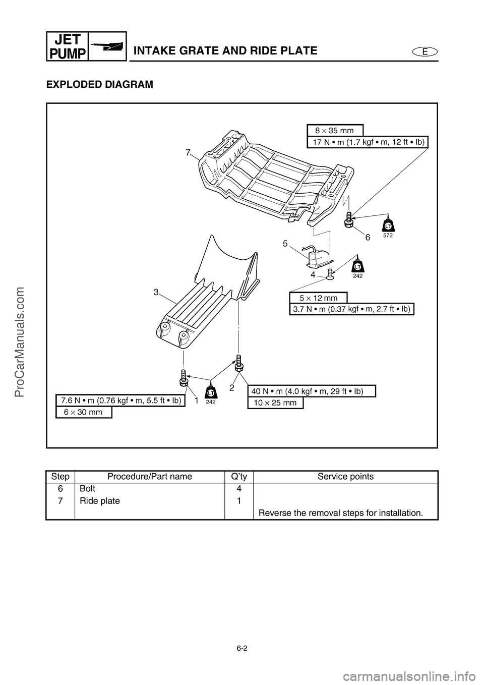
6-2
E
JET
PUMPINTAKE GRATE AND RIDE PLATE
EXPLODED DIAGRAM
Step Procedure/Part name Q’ty Service points
6Bolt 4
7 Ride plate 1
Reverse the removal steps for installation.
ProCarManuals.com
Page 202 of 347
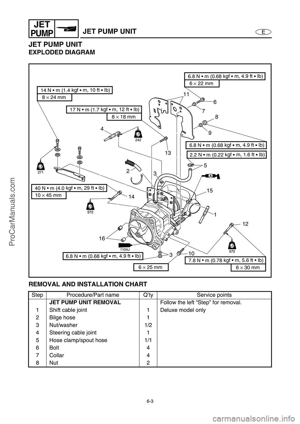
6-3
E
JET
PUMPJET PUMP UNIT
JET PUMP UNIT
EXPLODED DIAGRAM
REMOVAL AND INSTALLATION CHART
Step Procedure/Part name Q’ty Service points
JET PUMP UNIT REMOVAL
Follow the left “Step” for removal.
1 Shift cable joint 1 Deluxe model only
2 Bilge hose 1
3 Nut/washer 1/2
4 Steering cable joint 1
5 Hose clamp/spout hose 1/1
6Bolt 4
7 Collar 4
8Nut 2
8 × 24 mm
14 N • m (1.4 kgf
• m, 10 ft
• Ib)
6 × 22 mm
6.8 N • m (0.68 kgf
• m, 4.9 ft
• Ib)
2.2 N • m (0.22 kgf
• m, 1.6 ft
• Ib)
6.8 N • m (0.68 kgf
• m, 4.9 ft
• Ib)
10 × 45 mm
40 N • m (4.0 kgf
• m, 29 ft
• Ib)
11
76
5
3
16
312 1 15
LT
572
LT
572
LT
572
LT
572
LT
242
AA
LT
271
LT
4
14
2
10
13
6.8 N • m (0.68 kgf
• m, 4.9 ft
• Ib)
8
9
6 × 30 mm
7.8 N •
m (0.78 kgf • m, 5.6 ft • Ib) 8 × 18 mm
17 N • m (1.7 kgf
• m, 12 ft
• Ib)
6 × 25 mm
1104J
ProCarManuals.com